EP2146152A1 - Nebelerzeugervorrichtung - Google Patents
Nebelerzeugervorrichtung Download PDFInfo
- Publication number
- EP2146152A1 EP2146152A1 EP09164758A EP09164758A EP2146152A1 EP 2146152 A1 EP2146152 A1 EP 2146152A1 EP 09164758 A EP09164758 A EP 09164758A EP 09164758 A EP09164758 A EP 09164758A EP 2146152 A1 EP2146152 A1 EP 2146152A1
- Authority
- EP
- European Patent Office
- Prior art keywords
- mist
- air stream
- diameter droplet
- droplet mist
- small
- Prior art date
- Legal status (The legal status is an assumption and is not a legal conclusion. Google has not performed a legal analysis and makes no representation as to the accuracy of the status listed.)
- Granted
Links
Images



Classifications
-
- F—MECHANICAL ENGINEERING; LIGHTING; HEATING; WEAPONS; BLASTING
- F24—HEATING; RANGES; VENTILATING
- F24F—AIR-CONDITIONING; AIR-HUMIDIFICATION; VENTILATION; USE OF AIR CURRENTS FOR SCREENING
- F24F6/00—Air-humidification, e.g. cooling by humidification
- F24F6/02—Air-humidification, e.g. cooling by humidification by evaporation of water in the air
- F24F6/025—Air-humidification, e.g. cooling by humidification by evaporation of water in the air using electrical heating means
-
- F—MECHANICAL ENGINEERING; LIGHTING; HEATING; WEAPONS; BLASTING
- F24—HEATING; RANGES; VENTILATING
- F24F—AIR-CONDITIONING; AIR-HUMIDIFICATION; VENTILATION; USE OF AIR CURRENTS FOR SCREENING
- F24F6/00—Air-humidification, e.g. cooling by humidification
- F24F6/12—Air-humidification, e.g. cooling by humidification by forming water dispersions in the air
-
- A—HUMAN NECESSITIES
- A61—MEDICAL OR VETERINARY SCIENCE; HYGIENE
- A61H—PHYSICAL THERAPY APPARATUS, e.g. DEVICES FOR LOCATING OR STIMULATING REFLEX POINTS IN THE BODY; ARTIFICIAL RESPIRATION; MASSAGE; BATHING DEVICES FOR SPECIAL THERAPEUTIC OR HYGIENIC PURPOSES OR SPECIFIC PARTS OF THE BODY
- A61H33/00—Bathing devices for special therapeutic or hygienic purposes
- A61H33/06—Artificial hot-air or cold-air baths; Steam or gas baths or douches, e.g. sauna or Finnish baths
- A61H33/12—Steam baths for the face
-
- B—PERFORMING OPERATIONS; TRANSPORTING
- B05—SPRAYING OR ATOMISING IN GENERAL; APPLYING FLUENT MATERIALS TO SURFACES, IN GENERAL
- B05B—SPRAYING APPARATUS; ATOMISING APPARATUS; NOZZLES
- B05B5/00—Electrostatic spraying apparatus; Spraying apparatus with means for charging the spray electrically; Apparatus for spraying liquids or other fluent materials by other electric means
- B05B5/025—Discharge apparatus, e.g. electrostatic spray guns
- B05B5/057—Arrangements for discharging liquids or other fluent material without using a gun or nozzle
-
- F—MECHANICAL ENGINEERING; LIGHTING; HEATING; WEAPONS; BLASTING
- F24—HEATING; RANGES; VENTILATING
- F24F—AIR-CONDITIONING; AIR-HUMIDIFICATION; VENTILATION; USE OF AIR CURRENTS FOR SCREENING
- F24F6/00—Air-humidification, e.g. cooling by humidification
- F24F6/18—Air-humidification, e.g. cooling by humidification by injection of steam into the air
-
- F—MECHANICAL ENGINEERING; LIGHTING; HEATING; WEAPONS; BLASTING
- F25—REFRIGERATION OR COOLING; COMBINED HEATING AND REFRIGERATION SYSTEMS; HEAT PUMP SYSTEMS; MANUFACTURE OR STORAGE OF ICE; LIQUEFACTION SOLIDIFICATION OF GASES
- F25B—REFRIGERATION MACHINES, PLANTS OR SYSTEMS; COMBINED HEATING AND REFRIGERATION SYSTEMS; HEAT PUMP SYSTEMS
- F25B21/00—Machines, plants or systems, using electric or magnetic effects
- F25B21/02—Machines, plants or systems, using electric or magnetic effects using Peltier effect; using Nernst-Ettinghausen effect
-
- F—MECHANICAL ENGINEERING; LIGHTING; HEATING; WEAPONS; BLASTING
- F24—HEATING; RANGES; VENTILATING
- F24F—AIR-CONDITIONING; AIR-HUMIDIFICATION; VENTILATION; USE OF AIR CURRENTS FOR SCREENING
- F24F2221/00—Details or features not otherwise provided for
- F24F2221/12—Details or features not otherwise provided for transportable
-
- F—MECHANICAL ENGINEERING; LIGHTING; HEATING; WEAPONS; BLASTING
- F24—HEATING; RANGES; VENTILATING
- F24F—AIR-CONDITIONING; AIR-HUMIDIFICATION; VENTILATION; USE OF AIR CURRENTS FOR SCREENING
- F24F2221/00—Details or features not otherwise provided for
- F24F2221/38—Personalised air distribution
-
- F—MECHANICAL ENGINEERING; LIGHTING; HEATING; WEAPONS; BLASTING
- F24—HEATING; RANGES; VENTILATING
- F24F—AIR-CONDITIONING; AIR-HUMIDIFICATION; VENTILATION; USE OF AIR CURRENTS FOR SCREENING
- F24F6/00—Air-humidification, e.g. cooling by humidification
- F24F6/12—Air-humidification, e.g. cooling by humidification by forming water dispersions in the air
- F24F6/14—Air-humidification, e.g. cooling by humidification by forming water dispersions in the air using nozzles
Definitions
- the present invention relates to a mist generator device.
- a mist generator device may be used as a humidifier or a facial steamer.
- a conventional mist generator device generates two-types of mist, one is large-diameter droplet mist formed by micro-size droplets and the other is small-diameter droplet mist formed by nano-size droplets that are smaller than the micro-size droplets of the large-diameter droplet mist.
- the mist generator device simultaneously emits the two types of mist having droplets of different sizes.
- Japanese Laid-Open Patent Publication No. 2004-361009 describes a mist generator device including a large-diameter droplet mist generation unit, which generates large-diameter droplet mist by boiling water with a heater, and a small-diameter droplet mist generation unit, which generates small-diameter droplet mist with an electrostatic atomization mechanism.
- the mist generator device discharges the generated mists from a mist discharge port in a state suspended in an air stream, which is produced by a fan driven by a motor.
- the air stream produced by the fan is delivered through an air pipe to a large-diameter droplet mist outlet and to the small-diameter droplet mist generation unit.
- the air stream produced by the fan flows through the air pipe, which serves as a main air stream passage, and most of the air stream is delivered to the small-diameter droplet mist generation unit through an inlet.
- the small-diameter droplet mist generation unit generates the small-diameter droplet mist, which has a droplet size of about one to several tens of nanometers.
- the small-diameter droplet mist would be scattered if the air stream were to be delivered at a high flow rate to the small-diameter droplet mist generation unit. For this reason, it is difficult to increase the flow velocity of the small-diameter droplet mist.
- the mist generator device of the '009 publication is used as a humidifier for slowly delivering the small-diameter droplet mist to a closed space such as the room of a dwelling.
- this mist generator device is not effective for use as a facial steamer that delivers small-diameter droplet mist to an extremely limited area such as a face.
- the large-diameter droplet mist generated by heating liquid has a relatively high temperature.
- air stream is delivered at a high flow rate to the large-diameter droplet mist outlet.
- the flow rate of the air stream delivered to the large-diameter droplet mist outlet is lower than the flow rate of the air stream delivered to the small-diameter droplet mist generation unit.
- the flow rate of the air stream produced by the motor fan were to be increased at the large-diameter droplet mist outlet, this would scatter the small-diameter droplet mist.
- One aspect of the present invention is a mist generator device including a large-diameter droplet mist generation unit which generates heated large-diameter droplet mist from a liquid.
- a small-diameter droplet mist generation unit generates small-diameter droplet mist smaller than the large-diameter droplet mist by performing electrostatic atomization.
- An air stream produced by a fan passes through a main air stream passage.
- a sub-air stream passage is branched from the main air stream passage.
- a branched portion branches the sub-air stream passage from the main air stream passage and delivers to the sub-air stream passage an air stream having a flow rate lower than that of the air stream in the main air stream passage.
- a large-diameter droplet mist emission unit emits the large-diameter droplet mist generated in the large-diameter droplet mist generation unit out of the mist generator device.
- a small-diameter droplet mist emission unit emits the small-diameter droplet mist generated in the small-diameter droplet mist generation unit out of the mist generator device.
- the large-diameter droplet mist emission unit is arranged in the main air stream passage downstream from the branched portion, and the small-diameter droplet mist emission unit is arranged downstream from the sub-air stream passage.
- the mist generator device may be a cosmetic device such as an electric facial moisturizer which delivers a flow of mist toward a user.
- a cosmetic device such as an electric facial moisturizer which delivers a flow of mist toward a user.
- the frame of reference for the directions of "front”, “rear”, “left”, “right”, “up”, and “down” is the user of the cosmetic device (see Figs. 1 and 2 ).
- a cosmetic device 11 includes an annular base 12a, a cylindrical support 12b formed at the central part of the base 12a, and a spherical housing 12 fixed onto the support 12b.
- the housing 12 accommodates various types of mechanical and electrical components for the cosmetic device 11.
- An angle adjustor 12c is fitted into the housing 12 and supported to be rotatable in vertical and horizontal directions.
- a large-diameter droplet mist emission port 13 is arranged in the middle of the angle adjustor 12c.
- Large-diameter droplet mist such as micro-size droplet mist is emitted out of the cosmetic device 11 through the large-diameter droplet mist emission port 13.
- the large-diameter droplet mist may be generated by boiling liquid such as water and may be warm mist having a relatively high temperature than the small-diameter droplet mist.
- the user rotates the angle adjustor 12c to adjust the direction in which the large-diameter droplet mist emission port 13 emits the large-diameter droplet mist.
- a hood 13a is arranged near the large-diameter droplet mist emission port 13 to guide and set the direction of the large-diameter droplet mist emitted from the large-diameter droplet mist emission port 13.
- the hood 13a also functions to prevent the user from inadvertently touching the large-diameter droplet mist emission port 13.
- the hood 13a has, for example, a conical shape.
- the large-diameter droplet mist emission port 13 includes a mesh lid 13b to prevent the user from inadvertently inserting his or her hand or finger into the large-diameter droplet mist emission port 13.
- a small-diameter droplet mist emission port 14 is arranged below the large-diameter droplet mist emission port 13.
- the small-diameter droplet mist emission port 14 emits small-diameter droplet mist such as nano-size droplet mist, which droplet size is smaller than that of the large-diameter droplet mist.
- the small-diameter droplet mist may have a droplet size of about one to several tens of nanometers.
- An operation button 15 operated by the user when operating the cosmetic device 11 is arranged at the top of the housing 12.
- a tank holder 17 is arranged at the rear of the operation button 15.
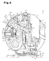
- a water storage tank 16 for storing water can be inserted to and removed from the tank holder 17 through an opening formed in the upper side of the tank holder 17 (see Fig. 3 ).
- a handle 18 for carrying the cosmetic device 11 is pivotally attached to the housing 12.
- a water supply pipe 17a has a basal end connected to the lower end of the tank holder 17 and a distal end connected to a warm mist generation mechanism 20.
- the warm mist generation mechanism 20 serves as a first mist generation unit, or a large-diameter droplet mist generation unit for generating large-diameter droplet mist by boiling the supplied water.
- the water supply pipe 17a supplies water from the water storage tank 16 to the warm mist generation mechanism 20.
- the warm mist generation mechanism 20 includes a boiler chamber 21, which accommodates a heater 22 for heating water. The heater 22 heats and boils the water that is supplied to the boiler chamber 21 to generate the large-diameter (warm) mist droplets.
- a mist guide tube 23 ha a basal end connected to a location above the boiler chamber 21.
- the mist guide tube 23 guides the large-diameter droplet mist generated in the boiler chamber 21.
- a discharge pipe 24 includes a basal end connected to a distal end of the mist guide tube 23.
- the discharge pipe 24 guides the large-diameter droplet mist toward the front.
- the discharge pipe 24 is tapered so that its diameter increases from the basal end towards the distal end (front side).
- a corrugated member 25 has basal end connected to the distal end of the discharge pipe 24 and a distal end, which is fixed to the angle adjustor 12c in close contact with the inner surface of the angle adjustor 12c.
- the corrugated member 25 is formed from a resilient or soft material such as silicone rubber.
- the large-diameter droplet mist emission port 13 in the angle adjustor 12c is arranged in the corrugated member 25.
- a mechanism for supplying the air stream for emitting the large-diameter droplet mist and the small-diameter droplet mist from the mist droplet emission ports 13 and 14 will now be described.
- a fan motor 32 is arranged in the housing 12 at the lower front side.
- the fan motor 32 draws in air from an air intake port (not shown) formed on the housing 12, generates an air stream, and forces out the air stream in an upward direction from an outlet 32a.
- the outlet 32a is connected to the basal end of an air pipe 30, which guides the air stream in an upward direction.
- the air pipe 30 defines a main air stream passage 33.
- the size of the air pipe 30, that is, the cross-sectional area of the main air stream passage 33 is set to be large enough so that it does not inhibit the flow of the air stream from the fan motor 32.
- the air pipe 30 has a free end, which is opposite to the basal end, connected to the fan motor 32.
- the free end is arranged in the discharge pipe 24.
- the main air stream passage 33 through which the air stream passes, is arranged in and surrounded by the mist supply passage 26, through which the large-diameter droplet mist passes.
- the main air stream passage 33 and the mist supply passage 26 at least partially form a double-pipe structure.
- the main air stream passage 33 and the mist supply passage 26 are examples of an inner pipe and an outer pipe of a double-pipe structure.
- the temperature of the air stream passing through the main air stream passage 33 is lower than the large-diameter droplet mist.
- the large-diameter droplet mist in the mist supply passage 26 is cooled by the main air stream passage 33 (air pipe 30).
- the dew condensed into water returns to the boiler chamber 21 through the mist supply passage 26.
- the large-diameter droplet mist emission port 13 includes a cylindrical mist guide 12d extending into the housing 12.
- the free end of the air pipe 30 is arranged in the mist guide 12d.
- the surface of the free end of the air pipe 30 defines an air discharge port 30c.
- the air stream passing through the main air stream passage 33 is discharged from the air discharge port 30c of the air pipe 30 and flows through the mist guide 12d. This will be described in more detail.
- the outer diameter of the free end of the air pipe 30 is slightly smaller than the inner diameter of the mist guide 12d.
- the cylindrical free end of the air pipe 30 is slightly inserted into the cylindrical mist guide 12d.
- This gap defines an elongated narrow inlet 34.
- the elongated narrow inlet 34 is located near the air discharge port 30c.
- the elongated narrow inlet 34 has an open area set to be smaller than the open area of the air discharge port 30c.
- the elongated narrow inlet 34 is formed by overlapping the cylindrical free end of the air pipe 30 and the mist guide 12d.
- the elongated narrow inlet 34 is an annular slit extending in the circumferential direction so as to continuously surround the entire circumference of the air discharge port 30c.
- the air discharge port 30c and the elongated narrow inlet 34 function as a mixing portion 35 for mixing the air stream passing through the main air stream passage 33 and the large-diameter droplet mist.
- the large-diameter droplet mist emission port 13 and the mixing portion 35 form a large-diameter droplet mist emission unit.
- the elongated narrow inlet 34 is one example of a large-diameter droplet mist outlet for drawing in large-diameter droplet mist flowing through the mist supply passage to the mixing portion 35.
- the dew condensed on the outer surface of the mist guide 12d does not enter the main air stream passage 33 from the air discharge port 30c.
- condensed water is not sprayed out of the large-diameter droplet mist emission port 13 by the air stream delivered from the fan motor 32.
- An annular flange 30a projects radially outward from the outer surface of the air pipe 30 ( Figs. 4 and 5 ).
- the annular flange 30a is arranged between the elongated narrow inlet 34 and the warm mist generation mechanism 20 in the mist supply passage 26.
- the annular flange 30a functions as a barrier for impeding the movement (flow) of the large-diameter droplet mist, which is generated by the warm mist generation mechanism 20, and prevents the large-diameter droplet mist from directly reaching the elongated narrow inlet 34.
- the large-diameter droplet mist generated in the warm mist generation mechanism 20 is first diffused when striking the annular flange 30a as they pass through the mist supply passage 26 and accumulate in the mist supply passage 26.
- a rectangular attachment hole 41 is formed in the front surface of the basal end of the air pipe 30.
- An electrostatic atomization mechanism 42 which serves as a second mist generation unit, or a small-diameter droplet mist generation unit for generating small-diameter droplet mist, is fixed to the air pipe 30 through the attachment hole 41.
- a side wall 30b extends towards the front of the cosmetic device 11 (in a direction substantially orthogonal to the direction in which the air stream flows through the air pipe 30) from one side of the attachment hole 41.
- the side wall 30b and a side surface of the electrostatic atomization mechanism 42 define a sub-air stream passage 43 branched from the main air stream passage 33.
- the sub-air stream passage 43 branches from the main air stream passage 33 and extends toward the front of the cosmetic device 11.
- the sub-air stream passage 43 is narrower than the main air stream passage 33.
- An air guide 40 which is for guiding some of the air stream delivered from the fan motor 32 and flowing through the main air stream passage 33 to the sub-air stream passage 43, is arranged on the inner surface of the air pipe 30.
- the air guide 40 includes a guide rib 40a and is ladle-shaped.
- the air guide 40 is tapered and inclined from the rear toward the front so as to approach the sub-air stream passage 43 at the downstream side (upper side) of the air pipe 30.
- Some of the air stream from the fan motor 32 is guided by the air guide 40 toward and into the sub-air stream passage 43.
- the air guide 40 also guides (delivers) to the sub-air stream passage 43 an air stream of which the flow rate is lower than the flow rate of the air stream in the main air stream passage 33. This will now be described in detail.
- the air guide 40 slightly projects slightly into the air pipe 30 (main air stream passage 33) and has a shape set so that the proportion of the cross-sectional area of the air guide 40 occupying the cross-sectional area of the main air stream passage 33 becomes low.
- the air guide 40 forms a branched portion 43 a.
- the electrostatic atomization mechanism 42 includes a needle-shaped discharge electrode 44 and an opposing electrode 45, which is located at a position facing the discharge electrode 44.
- the opposing electrode 45 is formed from a flat plate including a central vent hole 45a through which the air stream is passable. High voltage is applied between the discharge electrode 44 and the opposing electrode 45.
- a discharge area formed between the discharge electrode 44 and the opposing electrode 45 is located in the sub-air stream passage 43.
- the discharge electrode 44 has a basal end, which is in contact with a cooling surface of a Peltier unit (Peltier element) 46. The discharge electrode 44 is forcibly cooled by the Peltier unit 46.
- a heat radiating surface located opposite to the cooling surface of the Peltier unit 46 is arranged in the main air stream passage 33 (inner side of air pipe 30).
- Radiation fins 47 formed from metal (e.g., aluminum and copper) extend from the heat radiating surface of the Peltier unit 46.
- the radiation fins 47 are exposed to the interior of the main air stream passage 33.
- the air stream passing through the main air stream passage 33 promotes the radiation of heat from the heat radiating surface of the Peltier unit 46.
- the radiation fins 47 promote the radiation of heat from the heat radiating surface of the Peltier unit 46.
- the heat radiating surface of the Peltier unit 46 and the radiation fins 47 are arranged at the branched portion 43a of the main air stream passage 33 and the sub-air stream passage 43. This increases the amount of the air stream that comes into contact with the radiation fins 47 and thereby promotes the radiation of heat from the heat radiating surface of the Peltier unit 46.
- the radiation fins 47 may be reduced in size. By promoting the radiation of heat from the heat radiating surface, the cooling of the cooling surface of the Peltier unit 46 is promoted. In this embodiment, the radiation of heat from the heat radiating surface (radiation fins 47) is promoted to promote the cooling of the discharge electrode 44 with the Peltier unit 46.
- the electrostatic atomization mechanism 42 dew condenses on the surface of the discharge electrode 44 when the discharge electrode 44 is cooled by the Peltier unit 46.
- the water condensed at the surface of the discharge electrode 44 undergoes a Rayleigh breakup and becomes electrostatically atomized. This generates small-diameter droplet mist.
- the size of the small-diameter droplet mist may be about one to several tens of nanometers and is known to apply moisture and elasticity to the human skin when permeating the voids in the corneum surface of the human body.
- the electrostatic atomization mechanism 42 is covered by a sound deadening material holder 48 attached to the air pipe 30.
- the sound deadening material holder 48 includes a cylindrical holding portion 48a extending toward the front (small-diameter droplet mist emission port 14).
- a small-diameter droplet mist pipe 49 which is substantially cylindrical, is arranged in the holding portion 48a.
- the small-diameter droplet mist pipe 49 includes a basal end connected to the electrostatic atomization mechanism 42 and a distal end connected to the small-diameter droplet mist emission port 14.
- the small-diameter droplet mist pipe 49 guides the small-diameter droplet mist generated in the electrostatic atomization mechanism 42 to the small-diameter droplet mist emission port 14.
- the small-diameter droplet mist generated in the electrostatic atomization mechanism 42 mixes with the air stream passing through the sub-air stream passage 43 in the discharge area between the electrodes 44 and 45 and then passes through the small-diameter droplet mist pipe 49 to be emitted from the small-diameter droplet mist emission port 14.
- the small-diameter droplet mist emission port 14, the electrostatic atomization mechanism 42, and the small-diameter droplet mist pipe 49 form a small-diameter droplet mist emission unit.
- a substantially cylindrical sound deadening member 50 which is formed from a foam rubber, is press-fitted between the holding portion 48a of the sound deadening material holder 48 and the small-diameter droplet mist pipe 49.
- the sound deadening member 50 reduces the leakage of discharge noise produced by the discharge electrode 44 and the opposing electrode 45.
- the sound deadening member 50 has an inner end and an outer end that are in close contact with the small-diameter droplet mist pipe 49 and the inner surface of the housing 12.
- the sound deadening member 50 has an outer surface, which is in close contact with the inner surface of the holding portion 48a of the sound deadening material holder 48.
- the sound deadening member 50 thus fills the gap communicating the small-diameter droplet mist emission port 14 and the interior of the housing 12 (portion other than the flow passage through which the air stream and the mist pass) near the small-diameter droplet mist emission port 14.
- the sound deadening member 50 prevents air from being drawn into the housing 12 through the small-diameter droplet mist emission port 14. This prevents a reversed flow or scattering of the small-diameter droplet mist.
- the sound deadening member 50 also functions as a reversed flow prevention member.
- the water storage tank 16 supplies water to the boiler chamber 21 of the warm mist generation mechanism 20.
- the heater 22 heats and boils the water to generate the large-diameter droplet mist.
- the large-diameter droplet mist is guided from the boiler chamber 21 to the corrugated member 25 through the mist supply passage 26, as indicated by the arrow M1.
- the air stream generated by the fan motor 32 flows through the main air stream passage 33 and is discharged (ejected) from the air discharge port 30c, as indicated by the arrow A1.
- the air stream discharged from the air discharge port 30c produces a Venturi effect and generates negative pressure at the elongated narrow inlet 34 formed around the air discharge port 30c.
- the large-diameter droplet mist guided into the corrugated member 25 (mist supply passage 26) is forcibly drawn out of the mixing portion 35 by the negative pressure generated at the elongated narrow inlet 34 (as indicated by the arrow M2 in Fig. 4 ).
- the large-diameter droplet mist and the air stream are then mixed in the mixing portion 35 and emitted out of the housing 12 (cosmetic device 11) from the large-diameter droplet mist emission port 13.
- the air stream discharged from the air discharge port 30c is mixed with the large-diameter droplet mist drawn from the elongated narrow inlet 34.
- the flow velocity of the large-diameter droplet mist passing through the elongated narrow inlet 34 increases. This prevents dew condensation at the vicinity of the elongated narrow inlet 34.
- the elongated narrow inlet 34 extends continuously around the entire circumference of the air discharge port 30c. This uniformly delivers the large-diameter droplet mist around the air stream discharged from the air discharge port 30c.
- the air stream discharged from the air discharge port 30c and the large-diameter droplet mist are uniformly mixed in the mixing portion 35 and then emitted from the large-diameter droplet mist emission port 13.
- the large-diameter droplet mist guided from the warm mist generation mechanism 20 is diffused when striking the annular flange 30a projecting from the outer surface of the air pipe 30.
- the large-diameter droplet mist accumulates in the corrugated member 25 (mist supply passage 26) and is drawn out of the elongated narrow inlet 34 and into the mixing portion 35 after its temperature slightly decreases.
- the large-diameter droplet mist having a relatively high temperature and generated in the warm mist generation mechanism 20 is not directly drawn out of the elongated narrow inlet 34.
- the sub-air stream passage 43 guides the air stream to the discharge area between the discharge electrode 44 and the opposing electrode 45 of the electrostatic atomization mechanism 42.
- the electrostatic atomization mechanism 42 generates the small-diameter droplet mist, which is mixed with the air stream.
- the small-diameter droplet mist and the air stream then pass through the small-diameter droplet mist pipe 49 and are emitted out of the housing 12 (cosmetic device 11) from the small-diameter droplet mist emission port 14 (as indicated by the arrow A3 in Figs. 4 and 6 ).
- the present embodiment has the advantages described below.
- the radiation fins 47 may be arranged closer to the fan motor 32, that is, at the upstream side of the branched portion 43a of the main air stream passage 33 and the sub-air stream passage 43. This would increase the amount of air stream that comes into contact with the radiation fins 47.
- the heat radiating surface of the Peltier unit 46 may be arranged so as only contact the outer surface of the air pipe 30 instead of being arranged so as to be inserted into the main air stream passage 33 from the attachment hole 41. Such a structure would also radiate heat from the heat radiating surface of the Peltier unit 46 through the air pipe 30 with the air stream passing through the main air stream passage 33.
- the air pipe 30 may entirely be formed by a metal having a superior heat transfer property, and the radiation fins 47 may be eliminated.
- the radiation fins 47 may be eliminated. Such a structure would also radiate heat from the heat radiating surface of the Peltier unit 46 with the air stream passing through the main air stream passage 33.
- the annular flange 30a may be eliminated. Such a structure would also deliver the large-diameter droplet mist from the mist supply passage 26 to the mixing portion 35.
- the main air stream passage 33 may be arranged so as to surround the mist supply passage 26. Such a structure would also cool the large-diameter droplet mist in the mist supply passage 26 with the main air stream passage 33 (air pipe 30) through which the air stream having a temperature lower than the large-diameter droplet mist flows. Further, the air discharge port 30c and the elongated narrow inlet 34 may be arranged near each other. In other words, one of the main air stream passage 33 and the mist supply passage 26 may be arranged to surround the other one.
- the air discharge port 30c may be arranged to surround a discharge port for discharging the large-diameter droplet mist out of the mist supply passage 26 and into the mixing portion 35. Such a structure would also mix the large-diameter droplet mist with the air stream discharged out of the air discharge port 30c from the inner side of the air stream. This uniformly mixes the air stream, which is discharged from the air discharge port 30c, with the large-diameter droplet mist.
- the opening of the mist supply passage 26 be the elongated narrow inlet 34, which is an elongated narrow gap.
- an enlarged gap may be used in lieu of an elongated narrow gap.
- Such a structure would also mix the large-diameter droplet mist with the air stream, which is discharged from the air discharge port 30c, from around the air stream.
- the gap communicating the small-diameter droplet mist emission port 14 and the interior of the housing 12 is filled with the sound deadening member 50.
- the gap may be filled with an O-ring or a packing, which is discrete from the sound deadening member 50.
- the sound deadening member 50 there would be no need for a discrete component to fill the gap, and the number of components can be reduced.
- the corrugated member 25 is formed from a flexible material such as silicone rubber. Instead, the corrugated member 25 may be formed from plastic or metal.
- the mist guide 12d and the free end of the air pipe 30 need be cylindrical as long as they have conforming shapes.
- the free end of the air pipe 30 and the mist guide 12d may be formed to have the shape of a polygonal or elliptical tube.
- the elongated narrow inlet 34 extend continuously around the entire circumference of the air discharge port 30c.
- the elongated narrow inlet 34 may have any other form.
- a plurality of elongated narrow inlets 34 may be arranged at equal intervals around the air discharge port 30c.
- the elongated narrow inlet 34 may be formed by fine holes formed at the wall surface on the free end of the air pipe 30. Such a structure would also mix the large-diameter droplet mist with the air stream passing through the main air stream passage 33.
- the free end of the air pipe 30 may be spaced apart from the mist guide 12d such that the air pipe 30 is not inserted in the mist guide 12d. In such a case, the distance between the free end of the air pipe 30 and the open end of the mist guide 12d is set so as to form the elongated narrow inlet 34 between the ends.
- Such a structure would also mix the air stream discharged from the air discharge port 30c with the large-diameter droplet mist delivered through the mist supply passage 26 and emit the mixed air stream and large-diameter droplet mist from the large-diameter droplet mist emission port 13.
- the warm mist generation mechanism 20 generates the large-diameter droplet mist with the heater 22.
- the large-diameter droplet mist may be generated by a different mechanism.
- ultrasonic waves or a humidifier element may be used.
- a separate heater may be used to heat the generated large-diameter droplet mist and generate warm mist.
Landscapes
- Engineering & Computer Science (AREA)
- Chemical & Material Sciences (AREA)
- Mechanical Engineering (AREA)
- General Engineering & Computer Science (AREA)
- Combustion & Propulsion (AREA)
- Health & Medical Sciences (AREA)
- Public Health (AREA)
- Dispersion Chemistry (AREA)
- Epidemiology (AREA)
- Animal Behavior & Ethology (AREA)
- Physics & Mathematics (AREA)
- Pain & Pain Management (AREA)
- Physical Education & Sports Medicine (AREA)
- Rehabilitation Therapy (AREA)
- Life Sciences & Earth Sciences (AREA)
- Thermal Sciences (AREA)
- General Health & Medical Sciences (AREA)
- Veterinary Medicine (AREA)
- Devices For Medical Bathing And Washing (AREA)
- Air Humidification (AREA)
- Nozzles (AREA)
- Electrostatic Spraying Apparatus (AREA)
Applications Claiming Priority (1)
| Application Number | Priority Date | Filing Date | Title |
|---|---|---|---|
| JP2008179126A JP4697269B2 (ja) | 2008-07-09 | 2008-07-09 | ミスト発生装置 |
Publications (2)
| Publication Number | Publication Date |
|---|---|
| EP2146152A1 true EP2146152A1 (de) | 2010-01-20 |
| EP2146152B1 EP2146152B1 (de) | 2011-06-22 |
Family
ID=41151812
Family Applications (1)
| Application Number | Title | Priority Date | Filing Date |
|---|---|---|---|
| EP09164758A Active EP2146152B1 (de) | 2008-07-09 | 2009-07-07 | Nebelerzeugervorrichtung |
Country Status (5)
| Country | Link |
|---|---|
| EP (1) | EP2146152B1 (de) |
| JP (1) | JP4697269B2 (de) |
| KR (1) | KR20100006534A (de) |
| AT (1) | ATE514042T1 (de) |
| RU (1) | RU2421665C2 (de) |
Cited By (5)
| Publication number | Priority date | Publication date | Assignee | Title |
|---|---|---|---|---|
| CN102258421A (zh) * | 2010-05-25 | 2011-11-30 | 皇家飞利浦电子股份有限公司 | 用于向人脸传送雾的设备 |
| CN102499877A (zh) * | 2011-10-13 | 2012-06-20 | 浙江华光电器集团有限公司 | 一种离子蒸汽美容器及其控制方式 |
| CN108433862A (zh) * | 2018-03-08 | 2018-08-24 | 覃丽 | 一种冷敷及热敷自动护理用具 |
| CN113318308A (zh) * | 2021-06-08 | 2021-08-31 | 温亚利 | 一种高效补水美容仪器 |
| WO2023272931A1 (zh) * | 2021-06-28 | 2023-01-05 | 广东欧铠科技有限公司 | 一种水离子喷雾机构及应用其的电子设备 |
Families Citing this family (10)
| Publication number | Priority date | Publication date | Assignee | Title |
|---|---|---|---|---|
| JP2011200540A (ja) * | 2010-03-26 | 2011-10-13 | Panasonic Electric Works Co Ltd | ミスト発生装置 |
| JP5548581B2 (ja) * | 2010-10-22 | 2014-07-16 | パナソニック株式会社 | ミスト発生装置およびこれを備えた美容装置 |
| KR101277554B1 (ko) * | 2011-11-23 | 2013-06-21 | 주식회사 케이에이치바텍 | 차량 거치형의 미스트 발생 장치 |
| CN102818343B (zh) * | 2012-07-17 | 2014-07-30 | 格力电器(中山)小家电制造有限公司 | 一种气流切换装置和方法 |
| JP5963629B2 (ja) * | 2012-09-26 | 2016-08-03 | シャープ株式会社 | 加湿機 |
| WO2014050671A1 (ja) * | 2012-09-26 | 2014-04-03 | シャープ株式会社 | 加湿機 |
| JP6104188B2 (ja) * | 2014-01-29 | 2017-03-29 | 三菱電機株式会社 | 流体搬送装置 |
| KR101423288B1 (ko) * | 2014-05-27 | 2014-07-24 | 주식회사 이담테크 | 습윤공기 분사장치 |
| CN106511062B (zh) * | 2016-12-07 | 2018-12-04 | 佛山市顺德区盛熙电器制造有限公司 | 具有萃取功能的蒸脸器 |
| KR20220001409A (ko) | 2020-06-29 | 2022-01-05 | 주식회사 이엠텍 | 휴대용 스팀 미스트 장치 |
Citations (4)
| Publication number | Priority date | Publication date | Assignee | Title |
|---|---|---|---|---|
| JP2004361009A (ja) | 2003-06-04 | 2004-12-24 | Matsushita Electric Works Ltd | 加湿装置 |
| WO2008016180A1 (en) * | 2006-08-04 | 2008-02-07 | Panasonic Electric Works Co., Ltd. | Electrostatic atomizing apparatus for use in vehicle |
| JP2008079733A (ja) * | 2006-09-26 | 2008-04-10 | Ya Man Ltd | 噴霧装置 |
| JP2008179126A (ja) | 2006-12-25 | 2008-08-07 | Nissei Plastics Ind Co | 射出成形機の材料供給装置 |
Family Cites Families (8)
| Publication number | Priority date | Publication date | Assignee | Title |
|---|---|---|---|---|
| JPH0579336U (ja) * | 1992-03-27 | 1993-10-29 | 株式会社日立ホームテック | 電気温風機 |
| JP2000297952A (ja) * | 2000-01-01 | 2000-10-24 | Tiger Vacuum Bottle Co Ltd | 加湿方法と加湿器 |
| RU19906U1 (ru) * | 2001-03-12 | 2001-10-10 | Горбушин Анатолий Михайлович | Модульная установка кондиционирования воздуха |
| RU33209U1 (ru) * | 2003-05-06 | 2003-10-10 | Закрытое акционерное общество "Венттехком" | Аэрозольный генератор |
| JP2006046834A (ja) * | 2004-08-06 | 2006-02-16 | Daikin Ind Ltd | 加湿装置 |
| JP2006125743A (ja) * | 2004-10-29 | 2006-05-18 | Daikin Ind Ltd | 加湿装置およびそれを用いた空気清浄機 |
| JP4765556B2 (ja) * | 2005-10-31 | 2011-09-07 | パナソニック電工株式会社 | 静電霧化装置 |
| RU60683U1 (ru) * | 2006-08-04 | 2007-01-27 | Михаил Павлович Богданов | Увлажнитель воздуха (варианты) |
-
2008
- 2008-07-09 JP JP2008179126A patent/JP4697269B2/ja active Active
-
2009
- 2009-07-01 KR KR1020090059612A patent/KR20100006534A/ko not_active Ceased
- 2009-07-07 AT AT09164758T patent/ATE514042T1/de not_active IP Right Cessation
- 2009-07-07 EP EP09164758A patent/EP2146152B1/de active Active
- 2009-07-08 RU RU2009126342/06A patent/RU2421665C2/ru not_active IP Right Cessation
Patent Citations (4)
| Publication number | Priority date | Publication date | Assignee | Title |
|---|---|---|---|---|
| JP2004361009A (ja) | 2003-06-04 | 2004-12-24 | Matsushita Electric Works Ltd | 加湿装置 |
| WO2008016180A1 (en) * | 2006-08-04 | 2008-02-07 | Panasonic Electric Works Co., Ltd. | Electrostatic atomizing apparatus for use in vehicle |
| JP2008079733A (ja) * | 2006-09-26 | 2008-04-10 | Ya Man Ltd | 噴霧装置 |
| JP2008179126A (ja) | 2006-12-25 | 2008-08-07 | Nissei Plastics Ind Co | 射出成形機の材料供給装置 |
Cited By (11)
| Publication number | Priority date | Publication date | Assignee | Title |
|---|---|---|---|---|
| CN102258421A (zh) * | 2010-05-25 | 2011-11-30 | 皇家飞利浦电子股份有限公司 | 用于向人脸传送雾的设备 |
| WO2011148308A1 (en) | 2010-05-25 | 2011-12-01 | Koninklijke Philips Electronics N.V. | Device for delivering mist to the human face |
| RU2563450C2 (ru) * | 2010-05-25 | 2015-09-20 | Конинклейке Филипс Электроникс Н.В. | Устройство туманообразователя для ухода за лицом |
| CN102258421B (zh) * | 2010-05-25 | 2015-11-25 | 皇家飞利浦电子股份有限公司 | 用于向人脸传送雾的设备 |
| US10111806B2 (en) | 2010-05-25 | 2018-10-30 | Koninklijke Philips N.V. | Device for delivering mist to the human face |
| CN102499877A (zh) * | 2011-10-13 | 2012-06-20 | 浙江华光电器集团有限公司 | 一种离子蒸汽美容器及其控制方式 |
| CN102499877B (zh) * | 2011-10-13 | 2013-09-25 | 浙江华光电器集团有限公司 | 一种离子蒸汽美容器 |
| CN108433862A (zh) * | 2018-03-08 | 2018-08-24 | 覃丽 | 一种冷敷及热敷自动护理用具 |
| CN113318308A (zh) * | 2021-06-08 | 2021-08-31 | 温亚利 | 一种高效补水美容仪器 |
| CN113318308B (zh) * | 2021-06-08 | 2022-07-12 | 温亚利 | 一种高效补水美容仪器 |
| WO2023272931A1 (zh) * | 2021-06-28 | 2023-01-05 | 广东欧铠科技有限公司 | 一种水离子喷雾机构及应用其的电子设备 |
Also Published As
| Publication number | Publication date |
|---|---|
| RU2421665C2 (ru) | 2011-06-20 |
| ATE514042T1 (de) | 2011-07-15 |
| EP2146152B1 (de) | 2011-06-22 |
| RU2009126342A (ru) | 2011-01-20 |
| JP4697269B2 (ja) | 2011-06-08 |
| KR20100006534A (ko) | 2010-01-19 |
| JP2010017293A (ja) | 2010-01-28 |
Similar Documents
| Publication | Publication Date | Title |
|---|---|---|
| EP2146152B1 (de) | Nebelerzeugervorrichtung | |
| US10639666B2 (en) | Superparticle atomizing device | |
| JP4625267B2 (ja) | 静電霧化装置 | |
| US7350317B2 (en) | Electrostatic atomizing hairdryer and electrostatic atomizer | |
| ES2832800T3 (es) | Dispositivo de nebulización de un producto líquido, proceso para la desinfección por vía aérea y uso de este dispositivo para la desinfección por vía aérea | |
| CN101300079A (zh) | 静电雾化设备 | |
| WO2010029722A1 (ja) | 液体微細化装置とそれを用いた加湿装置 | |
| CN101700206B (zh) | 喷雾发生装置 | |
| JP5193900B2 (ja) | ミスト発生装置及び美容装置 | |
| US8241407B2 (en) | Electrostatically atomizing kit for use in a vehicle | |
| JP2009274069A (ja) | 静電霧化装置 | |
| JP2009045208A (ja) | 静電霧化装置及びこれを備えたヘアドライヤー | |
| JP6670255B2 (ja) | ミスト化および噴霧化システムおよび方法 | |
| JP4788835B2 (ja) | イオンミストによる髪の保湿方法及び髪の保湿装置 | |
| HK1143518A (en) | Mist generator device | |
| JP2011239821A (ja) | ミスト発生装置 | |
| JP2008284124A (ja) | サウナ用マイナスイオンミスト発生装置 | |
| JP5138620B2 (ja) | ミスト発生装置及び美容装置 | |
| JP2011000387A (ja) | 美容装置 | |
| JP2010104989A (ja) | イオンミストによる保湿方法 | |
| JP2011239823A (ja) | ミスト発生装置 | |
| JP2009079865A (ja) | 加湿装置 | |
| JP2025162782A (ja) | ミスト発生装置 | |
| JP2025162815A (ja) | ミスト発生装置 | |
| JP2025162801A (ja) | ミスト発生装置 |
Legal Events
| Date | Code | Title | Description |
|---|---|---|---|
| PUAI | Public reference made under article 153(3) epc to a published international application that has entered the european phase |
Free format text: ORIGINAL CODE: 0009012 |
|
| AK | Designated contracting states |
Kind code of ref document: A1 Designated state(s): AT BE BG CH CY CZ DE DK EE ES FI FR GB GR HR HU IE IS IT LI LT LU LV MC MK MT NL NO PL PT RO SE SI SK SM TR |
|
| AX | Request for extension of the european patent |
Extension state: AL BA RS |
|
| 17P | Request for examination filed |
Effective date: 20100127 |
|
| GRAP | Despatch of communication of intention to grant a patent |
Free format text: ORIGINAL CODE: EPIDOSNIGR1 |
|
| GRAS | Grant fee paid |
Free format text: ORIGINAL CODE: EPIDOSNIGR3 |
|
| GRAA | (expected) grant |
Free format text: ORIGINAL CODE: 0009210 |
|
| AK | Designated contracting states |
Kind code of ref document: B1 Designated state(s): AT BE BG CH CY CZ DE DK EE ES FI FR GB GR HR HU IE IS IT LI LT LU LV MC MK MT NL NO PL PT RO SE SI SK SM TR |
|
| REG | Reference to a national code |
Ref country code: GB Ref legal event code: FG4D |
|
| REG | Reference to a national code |
Ref country code: CH Ref legal event code: EP |
|
| REG | Reference to a national code |
Ref country code: IE Ref legal event code: FG4D |
|
| REG | Reference to a national code |
Ref country code: DE Ref legal event code: R096 Ref document number: 602009001598 Country of ref document: DE Effective date: 20110804 |
|
| REG | Reference to a national code |
Ref country code: NL Ref legal event code: VDEP Effective date: 20110622 |
|
| PG25 | Lapsed in a contracting state [announced via postgrant information from national office to epo] |
Ref country code: HR Free format text: LAPSE BECAUSE OF FAILURE TO SUBMIT A TRANSLATION OF THE DESCRIPTION OR TO PAY THE FEE WITHIN THE PRESCRIBED TIME-LIMIT Effective date: 20110622 Ref country code: LT Free format text: LAPSE BECAUSE OF FAILURE TO SUBMIT A TRANSLATION OF THE DESCRIPTION OR TO PAY THE FEE WITHIN THE PRESCRIBED TIME-LIMIT Effective date: 20110622 Ref country code: NO Free format text: LAPSE BECAUSE OF FAILURE TO SUBMIT A TRANSLATION OF THE DESCRIPTION OR TO PAY THE FEE WITHIN THE PRESCRIBED TIME-LIMIT Effective date: 20110922 Ref country code: SE Free format text: LAPSE BECAUSE OF FAILURE TO SUBMIT A TRANSLATION OF THE DESCRIPTION OR TO PAY THE FEE WITHIN THE PRESCRIBED TIME-LIMIT Effective date: 20110622 |
|
| PG25 | Lapsed in a contracting state [announced via postgrant information from national office to epo] |
Ref country code: CY Free format text: LAPSE BECAUSE OF FAILURE TO SUBMIT A TRANSLATION OF THE DESCRIPTION OR TO PAY THE FEE WITHIN THE PRESCRIBED TIME-LIMIT Effective date: 20110622 Ref country code: FI Free format text: LAPSE BECAUSE OF FAILURE TO SUBMIT A TRANSLATION OF THE DESCRIPTION OR TO PAY THE FEE WITHIN THE PRESCRIBED TIME-LIMIT Effective date: 20110622 Ref country code: AT Free format text: LAPSE BECAUSE OF FAILURE TO SUBMIT A TRANSLATION OF THE DESCRIPTION OR TO PAY THE FEE WITHIN THE PRESCRIBED TIME-LIMIT Effective date: 20110622 Ref country code: GR Free format text: LAPSE BECAUSE OF FAILURE TO SUBMIT A TRANSLATION OF THE DESCRIPTION OR TO PAY THE FEE WITHIN THE PRESCRIBED TIME-LIMIT Effective date: 20110923 Ref country code: LV Free format text: LAPSE BECAUSE OF FAILURE TO SUBMIT A TRANSLATION OF THE DESCRIPTION OR TO PAY THE FEE WITHIN THE PRESCRIBED TIME-LIMIT Effective date: 20110622 Ref country code: SI Free format text: LAPSE BECAUSE OF FAILURE TO SUBMIT A TRANSLATION OF THE DESCRIPTION OR TO PAY THE FEE WITHIN THE PRESCRIBED TIME-LIMIT Effective date: 20110622 |
|
| PG25 | Lapsed in a contracting state [announced via postgrant information from national office to epo] |
Ref country code: BE Free format text: LAPSE BECAUSE OF FAILURE TO SUBMIT A TRANSLATION OF THE DESCRIPTION OR TO PAY THE FEE WITHIN THE PRESCRIBED TIME-LIMIT Effective date: 20110622 Ref country code: NL Free format text: LAPSE BECAUSE OF FAILURE TO SUBMIT A TRANSLATION OF THE DESCRIPTION OR TO PAY THE FEE WITHIN THE PRESCRIBED TIME-LIMIT Effective date: 20110622 Ref country code: MT Free format text: LAPSE BECAUSE OF FAILURE TO SUBMIT A TRANSLATION OF THE DESCRIPTION OR TO PAY THE FEE WITHIN THE PRESCRIBED TIME-LIMIT Effective date: 20110622 |
|
| PG25 | Lapsed in a contracting state [announced via postgrant information from national office to epo] |
Ref country code: EE Free format text: LAPSE BECAUSE OF FAILURE TO SUBMIT A TRANSLATION OF THE DESCRIPTION OR TO PAY THE FEE WITHIN THE PRESCRIBED TIME-LIMIT Effective date: 20110622 Ref country code: IS Free format text: LAPSE BECAUSE OF FAILURE TO SUBMIT A TRANSLATION OF THE DESCRIPTION OR TO PAY THE FEE WITHIN THE PRESCRIBED TIME-LIMIT Effective date: 20111022 Ref country code: PT Free format text: LAPSE BECAUSE OF FAILURE TO SUBMIT A TRANSLATION OF THE DESCRIPTION OR TO PAY THE FEE WITHIN THE PRESCRIBED TIME-LIMIT Effective date: 20111024 Ref country code: CZ Free format text: LAPSE BECAUSE OF FAILURE TO SUBMIT A TRANSLATION OF THE DESCRIPTION OR TO PAY THE FEE WITHIN THE PRESCRIBED TIME-LIMIT Effective date: 20110622 |
|
| PG25 | Lapsed in a contracting state [announced via postgrant information from national office to epo] |
Ref country code: MC Free format text: LAPSE BECAUSE OF NON-PAYMENT OF DUE FEES Effective date: 20110731 Ref country code: PL Free format text: LAPSE BECAUSE OF FAILURE TO SUBMIT A TRANSLATION OF THE DESCRIPTION OR TO PAY THE FEE WITHIN THE PRESCRIBED TIME-LIMIT Effective date: 20110622 Ref country code: SK Free format text: LAPSE BECAUSE OF FAILURE TO SUBMIT A TRANSLATION OF THE DESCRIPTION OR TO PAY THE FEE WITHIN THE PRESCRIBED TIME-LIMIT Effective date: 20110622 |
|
| REG | Reference to a national code |
Ref country code: IE Ref legal event code: MM4A |
|
| PLBE | No opposition filed within time limit |
Free format text: ORIGINAL CODE: 0009261 |
|
| STAA | Information on the status of an ep patent application or granted ep patent |
Free format text: STATUS: NO OPPOSITION FILED WITHIN TIME LIMIT |
|
| REG | Reference to a national code |
Ref country code: FR Ref legal event code: ST Effective date: 20120406 |
|
| 26N | No opposition filed |
Effective date: 20120323 |
|
| PG25 | Lapsed in a contracting state [announced via postgrant information from national office to epo] |
Ref country code: IT Free format text: LAPSE BECAUSE OF FAILURE TO SUBMIT A TRANSLATION OF THE DESCRIPTION OR TO PAY THE FEE WITHIN THE PRESCRIBED TIME-LIMIT Effective date: 20110622 |
|
| PG25 | Lapsed in a contracting state [announced via postgrant information from national office to epo] |
Ref country code: DK Free format text: LAPSE BECAUSE OF FAILURE TO SUBMIT A TRANSLATION OF THE DESCRIPTION OR TO PAY THE FEE WITHIN THE PRESCRIBED TIME-LIMIT Effective date: 20110622 |
|
| REG | Reference to a national code |
Ref country code: DE Ref legal event code: R097 Ref document number: 602009001598 Country of ref document: DE Effective date: 20120323 |
|
| PG25 | Lapsed in a contracting state [announced via postgrant information from national office to epo] |
Ref country code: IE Free format text: LAPSE BECAUSE OF NON-PAYMENT OF DUE FEES Effective date: 20110707 |
|
| PG25 | Lapsed in a contracting state [announced via postgrant information from national office to epo] |
Ref country code: FR Free format text: LAPSE BECAUSE OF NON-PAYMENT OF DUE FEES Effective date: 20110822 |
|
| PGFP | Annual fee paid to national office [announced via postgrant information from national office to epo] |
Ref country code: DE Payment date: 20120704 Year of fee payment: 4 |
|
| PG25 | Lapsed in a contracting state [announced via postgrant information from national office to epo] |
Ref country code: MK Free format text: LAPSE BECAUSE OF FAILURE TO SUBMIT A TRANSLATION OF THE DESCRIPTION OR TO PAY THE FEE WITHIN THE PRESCRIBED TIME-LIMIT Effective date: 20110622 |
|
| PG25 | Lapsed in a contracting state [announced via postgrant information from national office to epo] |
Ref country code: SM Free format text: LAPSE BECAUSE OF FAILURE TO SUBMIT A TRANSLATION OF THE DESCRIPTION OR TO PAY THE FEE WITHIN THE PRESCRIBED TIME-LIMIT Effective date: 20110622 Ref country code: ES Free format text: LAPSE BECAUSE OF FAILURE TO SUBMIT A TRANSLATION OF THE DESCRIPTION OR TO PAY THE FEE WITHIN THE PRESCRIBED TIME-LIMIT Effective date: 20111003 |
|
| PG25 | Lapsed in a contracting state [announced via postgrant information from national office to epo] |
Ref country code: LU Free format text: LAPSE BECAUSE OF NON-PAYMENT OF DUE FEES Effective date: 20110707 |
|
| PG25 | Lapsed in a contracting state [announced via postgrant information from national office to epo] |
Ref country code: BG Free format text: LAPSE BECAUSE OF FAILURE TO SUBMIT A TRANSLATION OF THE DESCRIPTION OR TO PAY THE FEE WITHIN THE PRESCRIBED TIME-LIMIT Effective date: 20110922 |
|
| PG25 | Lapsed in a contracting state [announced via postgrant information from national office to epo] |
Ref country code: TR Free format text: LAPSE BECAUSE OF FAILURE TO SUBMIT A TRANSLATION OF THE DESCRIPTION OR TO PAY THE FEE WITHIN THE PRESCRIBED TIME-LIMIT Effective date: 20110622 |
|
| PG25 | Lapsed in a contracting state [announced via postgrant information from national office to epo] |
Ref country code: HU Free format text: LAPSE BECAUSE OF FAILURE TO SUBMIT A TRANSLATION OF THE DESCRIPTION OR TO PAY THE FEE WITHIN THE PRESCRIBED TIME-LIMIT Effective date: 20110622 |
|
| REG | Reference to a national code |
Ref country code: CH Ref legal event code: PL |
|
| GBPC | Gb: european patent ceased through non-payment of renewal fee |
Effective date: 20130707 |
|
| REG | Reference to a national code |
Ref country code: DE Ref legal event code: R119 Ref document number: 602009001598 Country of ref document: DE Effective date: 20140201 |
|
| PG25 | Lapsed in a contracting state [announced via postgrant information from national office to epo] |
Ref country code: LI Free format text: LAPSE BECAUSE OF NON-PAYMENT OF DUE FEES Effective date: 20130731 Ref country code: DE Free format text: LAPSE BECAUSE OF NON-PAYMENT OF DUE FEES Effective date: 20140201 Ref country code: CH Free format text: LAPSE BECAUSE OF NON-PAYMENT OF DUE FEES Effective date: 20130731 Ref country code: GB Free format text: LAPSE BECAUSE OF NON-PAYMENT OF DUE FEES Effective date: 20130707 |