EP2146178A2 - Panneau de blindage - Google Patents
Panneau de blindage Download PDFInfo
- Publication number
- EP2146178A2 EP2146178A2 EP09165659A EP09165659A EP2146178A2 EP 2146178 A2 EP2146178 A2 EP 2146178A2 EP 09165659 A EP09165659 A EP 09165659A EP 09165659 A EP09165659 A EP 09165659A EP 2146178 A2 EP2146178 A2 EP 2146178A2
- Authority
- EP
- European Patent Office
- Prior art keywords
- metal
- carbide
- armor
- cemented carbide
- armor panel
- Prior art date
- Legal status (The legal status is an assumption and is not a legal conclusion. Google has not performed a legal analysis and makes no representation as to the accuracy of the status listed.)
- Withdrawn
Links
Images


Classifications
-
- F—MECHANICAL ENGINEERING; LIGHTING; HEATING; WEAPONS; BLASTING
- F41—WEAPONS
- F41H—ARMOUR; ARMOURED TURRETS; ARMOURED OR ARMED VEHICLES; MEANS OF ATTACK OR DEFENCE, e.g. CAMOUFLAGE, IN GENERAL
- F41H5/00—Armour; Armour plates
- F41H5/02—Plate construction
- F41H5/04—Plate construction composed of more than one layer
- F41H5/0414—Layered armour containing ceramic material
-
- F—MECHANICAL ENGINEERING; LIGHTING; HEATING; WEAPONS; BLASTING
- F41—WEAPONS
- F41H—ARMOUR; ARMOURED TURRETS; ARMOURED OR ARMED VEHICLES; MEANS OF ATTACK OR DEFENCE, e.g. CAMOUFLAGE, IN GENERAL
- F41H5/00—Armour; Armour plates
- F41H5/02—Plate construction
- F41H5/04—Plate construction composed of more than one layer
- F41H5/0492—Layered armour containing hard elements, e.g. plates, spheres, rods, separated from each other, the elements being connected to a further flexible layer or being embedded in a plastics or an elastomer matrix
-
- F—MECHANICAL ENGINEERING; LIGHTING; HEATING; WEAPONS; BLASTING
- F41—WEAPONS
- F41H—ARMOUR; ARMOURED TURRETS; ARMOURED OR ARMED VEHICLES; MEANS OF ATTACK OR DEFENCE, e.g. CAMOUFLAGE, IN GENERAL
- F41H5/00—Armour; Armour plates
- F41H5/02—Plate construction
-
- Y—GENERAL TAGGING OF NEW TECHNOLOGICAL DEVELOPMENTS; GENERAL TAGGING OF CROSS-SECTIONAL TECHNOLOGIES SPANNING OVER SEVERAL SECTIONS OF THE IPC; TECHNICAL SUBJECTS COVERED BY FORMER USPC CROSS-REFERENCE ART COLLECTIONS [XRACs] AND DIGESTS
- Y10—TECHNICAL SUBJECTS COVERED BY FORMER USPC
- Y10T—TECHNICAL SUBJECTS COVERED BY FORMER US CLASSIFICATION
- Y10T29/00—Metal working
- Y10T29/49—Method of mechanical manufacture
Definitions
- This invention relates to armor panels, in particularly composite armor panels comprising one or more protective layers.
- a standard armor panel of the kind to which the present invention particularly refers comprises a multitude of layers, designed to gradually absorb the kinetic energy of the impact, delivered to the panel by an incoming projectile and finally to completely avoid penetration of the projectile or its fragments to the body to be protected.
- the layers used in such armor panels may be divided into two groups: hard layers, e.g. steel or ceramic, and soft layers, e.g. Aramid or UHMW HDPE (Ultra High Molecular Weight High Density PolyEthylene).
- hard layers e.g. steel or ceramic
- soft layers e.g. Aramid or UHMW HDPE (Ultra High Molecular Weight High Density PolyEthylene).
- the harder layers are usually positioned facing the expected threat and absorb most of its kinetic energy thereof, thereby slowing it down and shattering and/or deforming it substantially.
- the softer layers absorb the remains of the kinetic energy of the projectile, stopping it and its fragments, thereby preventing them from deforming/coming in contact with the body to be protected or at least from penetrating it.
- a hard ceramic layer may be light-weight, yet brittle, while a hard steel layer having similar ballistic properties, may be very heavy, though easy to work with.
- an armor panel for protecting a body from an incoming projectile having an expected impact direction, said armor panel comprising at least an armor layer made of cemented carbide in the form of metal-carbide aggregate embedded within a metal binder matrix.
- the armor panel may be adapted to protect the human body, i.e. be in the form of personal armor such as a vest, or alternatively, be designed to protect a structure, mobile or immobile, adapted to house individuals to be protected, e.g. a vehicle.
- the 'metal-carbide aggregate' should be understood as being in the form of granular/powder material, and 'embedded within a metal binder matrix' should be understood as being homogenously spread throughout the metal binder matrix.
- cemented carbide may be divided into two major groups, a first group in which the cemented carbide comprises a carbide aggregate embedded within a binder matrix, and a second group in which the cemented carbide comprises an aggregate without a binder.
- the metal of said metal-carbide will be referred herein as 'carbide metal' and the metal used for said metal binder matrix will be referred herein as 'binder metal'.
- Said carbide metal and said binder metal may differ in their inherent characteristics. More particularly, the properties of said carbide and said binder metal may differ from one another.
- the metal of said carbide metal may be chosen from a group of refractory metals, in order to provide said cemented carbide with high hardness, high fracture toughness and a high melting point.
- the metal of the binder metal may be a metal having a lower hardness than that of the metal of the metal-carbide, in order to reduce the brittleness of the cemented carbide and provide it with high fracture toughness.
- Cemented carbide may be manufactured by a variety of processes in solid, liquid and vapor phases as known per se , for example hot isostatic pressing (HIP) or sintering. During manufacture, binder metal and carbide are heated up until the binder metal is melted down while the aggregate remains in solid phase, thereby providing the cemented carbide with its desired morphology. This is due to the carbide having a higher melting point than that of the binder metal.
- HIP hot isostatic pressing
- the carbide metals are so chosen as to provide the metal-carbide with relatively high density, high toughness and hardness.
- the metal-carbides described above may have a density ranging from 4.93ö15.8 gr/cc, a toughness ranging from 240ö550 MPa, hardness ranging from 1400ö3000 HV50and a melting point ranging from 1800ö3990°C.
- Fracture toughness of the above metal-carbides is relatively not high, e.g. up to about 12 Mpa*(m 1/2 ).
- Some examples of such metal-carbides may be WC, TiC, TaC, NbC, ZrC, HfC, VC, Cr3C2, Mo2C etc.
- the cemented carbide may comprise several carbide metals forming several kinds of aggregates while using the same metal binder.
- Some examples of such cemented carbides may be WC-Co, WC-TiC-TaC-NbC-Co, WC-Cr3C2-Co, WC-TiC-TaC-NbC-Cr3C2-Co, TiCN-WC-TiC-TaC-NbC-Ni-Co-Mo2C-VC.
- Said binder metal may have a density ranging from 7.8ö8.9 gr/cc, fracture toughness ranging up to 400 Mpa*(m 1/2 ) which is considerably higher than that of the metal-carbides, and a melting point ranging from 1450ö1536°C.
- Some examples of such binder metals may be Co, Ni, Fe etc.
- the binder metals listed above have an atomic weight essentially lower than that of the carbide metals, providing the cemented carbide used for the armor panel with an essentially lower overall density than a similar cemented carbide in which the metal (such as W, Ti, Nb etc.) is of an atomic weight close to that of the carbide metals.
- the metal-carbide aggregate may be in the form of grains homogenously spread throughout the binder.
- the grain size of the metal-carbide aggregate may be such that it does not exceed 20 ⁇ m per grain.
- the grain size may range between about 0.5 ⁇ mö2.3 ⁇ m, more particularly between 0.7 ⁇ mö2.1 ⁇ m, and still more particularly between 0.9 ⁇ mö1.9 ⁇ m, and having an average grain size of about 1.3 ⁇ m.
- the grain size may range between about 2.5 ⁇ mö6.2 ⁇ m, more particularly between 2.7 ⁇ mö6 ⁇ m, and still more particularly between 2.9 ⁇ mö5.8 ⁇ m, and having an average grain size of about 2.7 ⁇ m.
- the composition of the cemented carbide may be such that, by weight percentage, the metal carbide aggregate does not exceed 80%.
- the metal carbide aggregate may constitute between about 80ö96%, more particularly between about 85ö94%, and still more particularly between about 90ö92%.
- the metal binder matrix may be such that, by weight, does not exceed 80%.
- the metal binder matrix may constitute between about 4%ö20%, more particularly between about 6%ö15%, and still more particularly between about 8%ö10%.
- the composition of the cemented carbide may also be such that, by volume percentage, the metal carbide aggregate does not exceed 70%.
- the metal carbide aggregate may constitute between about 82ö96%, more particularly between about 86ö92%, and still more particularly between about 88ö90%.
- the metal binder matrix may be such that, by volume, does not exceed 30%.
- the metal binder matrix may constitute between about 4%ö18%, more particularly between about 8%ö14%, and still more particularly between about 10%ö12%.
- the cemented carbide may comprise metal carbide aggregates of various metal, for example both titanium carbide (TiC) aggregates and tungsten carbide (WC) aggregates.
- the composition of the cemented carbide may be such that, by weight, WC ranges between 70%ö85%, more particularly between 74%ö80%, and still more particularly between 76%ö79%.
- the weight percentage of the titanium carbide (TiC) may range between 10%ö20%, more particularly between 12%ö18%, and still more particularly between 14%ö16%.
- the weight percentage of the binder may range between 4%ö20%, more particularly between 6%ö15%, and still more particularly between 8%ö10%.
- the composition of the cemented carbide may be such that, by volume, WC may range between 50%ö65%, more particularly between 53%ö62%, and still more particularly between 56%ö60%.
- the volume percentage of the titanium carbide (TiC) may range between 24%ö40%, more particularly between 27%ö36%, and still more particularly between 30%ö33%.
- the volume percentage of the binder may range between 4%ö16%, more particularly between 6%ö14%, and still more particularly between 9%ö12%.
- the said cemented carbide may have an overall density ranging from 5.5ö15.5 gr/cc, a toughness ranging from 1.7-4.1 GPa, hardness ranging from 87ö93 HRa, and fracture toughness up to 20 Mpa*(m 1/2 ), i.e. lower than that of the binder metal yet higher that of the metal-carbide.
- compositions are chosen specifically in order to provide the cemented carbide, on the one hand, with high hardness due to the metal-carbide aggregate, and on the other hand, high fracture toughness due to the metal-binder matrix.
- the cemented carbide is used in an armor panel, the composition is chosen such that it may be adapted to withstand a high impact during a short time interval.
- the armor panel may also comprise a layer which is partially made of cemented carbide, for example, containing cemented carbide pellets and/or tiles.
- pellets' should be understood to refer to armor elements adapted to be incorporated within the armor panel, and usually having a polygonal/cylindrical shape extending along a central axis.
- the design of the armor panel may be such that the pellets/tiles are incorporated within a matrix which is of different characteristics than that of the metal-binder matrix, for example, made of a light weight metal (e.g. aluminum) or a thermoplastic/thermosetic polymer (e.g. resin).
- this layer exhibits uniform mechanical properties as in known, and widely used in the field of armor, ceramic tiles, and on the other hand, may be essentially less brittle then these tiles (due to the inherent ductile properties of the binder metal), due to which the armor layer may have a high multi-hit capability compatible to that of an armor layer made of metal carbide pellets or armor elements within a matrix, and the ability to be processed, in particular cut, without causing its fracture, e.g. using CNC tools, to have a desired design.
- the armor panel may comprise two or more layers which may be made of the same or different cemented carbides.
- Said armor panel may comprise in addition to the at least one layer of cemented carbide, a complementary armor layer positioned in front or behind said cemented carbide layer, and/or an optional a backing layer.
- the additional layers may be made of any appropriate ballistic materials, such as steel, metal, ceramic or any other ballistic material.
- cemented carbide layer either alone or with additional layers.
- materials and processes that may be used for the manufacture of the cemented carbide layer are generally presented in the Summary of Invention, whilst for the purpose of the present detailed description, one specific non-limiting example of the cemented carbide will be referred to, which is a cemented carbide produced from tungsten carbide as a metal-carbide aggregate with cobalt as a binder metal, by a process including heating up both the binder metal and the carbide to high temperatures of about 1600 °C.
- the melting point of the carbide in this case tungsten-carbide ( ⁇ 1800 °C) is higher than that of the cobalt binder ( ⁇ 1550 °C)
- the cobalt binder is melted to assume a liquid phase while the tungsten-carbide aggregate remains in solid state. This manufacturing process provides even dispersion of the aggregate within the binder and causes the resulting cemented carbide to have extremely low porosity, e.g. about 2%.
- Figs. 2B shows morphological representation of a cemented carbide of the kind used in armor panels according to the present invention, in particular such as in the specific example described above.
- the carbide metal aggregate 42 is formed in clusters (shown in gray) and is bound by a binder 44 (shown in white).
- the clusters 42 are immersed in the binder 44, i.e. the connection of the clusters 42 to the binder 44 is achieved by the clusters 42 being a kind of dissolved in, and homogenously spread throughout, the metal binder 44.
- Fig. 2C shows a cemented carbide of a different kind where no metal binder matrix is used.
- the cemented carbide shown in Fig. 2C comprises WC clusters 52 (gray), TiC clusters 54 (dark gray), and TaC clusters 56 (light gray).
- WC clusters 52 gray
- TiC clusters 54 dark gray
- TaC clusters 56 light gray
- the presence of the binder provides the material with fracture toughness of up to 20 Mpa*(m 1/2 ), as opposed to about 12 Mpa*(m 1/2 ) of the material shown in Fig. 2C .
- Increased fracture toughness may allow for a higher multi-hit capability of the armor panel.
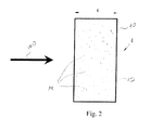
- an armor panel according to the present invention is shown, made of a monolith layer 10 of the cemented carbide, constituted by a metal binder matrix 12 and a carbide aggregate 14.
- the armor panel 1 has been produced with a thickness t of 10mm and an areal weight w approx. 69 Kg/m 2 .
- the armor panel 1 has appeared to provide the same level of protection (level 3 threats according to STANAG 4569), as that of the armor panel 1 and withstand AP rounds and FSP. It should also be appreciated that the armor panel 1 may provide protection against hollow charges as well.
- the armor panel 1' comprises a first layer 10 of the cemented carbide and a second layer 20 of steel, and such combination appears to improve anti-penetration ability of the entire armor panel.
- arrow 100 denotes the expected impact direction.
- the panel 1' may for example, be produced with a thickness t' of the first, cemented carbide layer 10 being 4mm and a thickness T' of the second, steel layer 20 being 5mm.
- a thickness t' of the first, cemented carbide layer 10 being 4mm
- a thickness T' of the second, steel layer 20 being 5mm.
- the armor panel 1" comprises a first layer 10 of the cemented carbide and a second layer 30 made of a plurality of HDPE sheets.
- the panel 1" may, for example, be produced with a thickness t" of the first, cemented carbide layer 10 being 4mm, and a thickness T' of the second, HDPE layer 30 being 23mm.
- Such an armor panel 1" has also been shown to withstand the same threats as those withstood by the reference armor panel 1, though being essentially lighter.
- the armor panel 1'' comprises a first layer 10 of cemented carbide, a second layer 20 of steel, and a third, backing layer 30 made of a plurality of Kevlar® sheets.
- the armor panel according to the present invention is capable to provide at least the same ballistic protection as the reference armor panel RP, however, with reduced overall weight and thickness.
Landscapes
- Engineering & Computer Science (AREA)
- General Engineering & Computer Science (AREA)
- Chemical & Material Sciences (AREA)
- Ceramic Engineering (AREA)
- Aiming, Guidance, Guns With A Light Source, Armor, Camouflage, And Targets (AREA)
- Laminated Bodies (AREA)
Applications Claiming Priority (1)
| Application Number | Priority Date | Filing Date | Title |
|---|---|---|---|
| IL192894A IL192894A0 (en) | 2008-07-17 | 2008-07-17 | Armor panel |
Publications (2)
| Publication Number | Publication Date |
|---|---|
| EP2146178A2 true EP2146178A2 (fr) | 2010-01-20 |
| EP2146178A3 EP2146178A3 (fr) | 2012-10-17 |
Family
ID=40991499
Family Applications (1)
| Application Number | Title | Priority Date | Filing Date |
|---|---|---|---|
| EP09165659A Withdrawn EP2146178A3 (fr) | 2008-07-17 | 2009-07-16 | Panneau de blindage |
Country Status (3)
| Country | Link |
|---|---|
| US (2) | US20100011949A1 (fr) |
| EP (1) | EP2146178A3 (fr) |
| IL (1) | IL192894A0 (fr) |
Families Citing this family (6)
| Publication number | Priority date | Publication date | Assignee | Title |
|---|---|---|---|---|
| US11015903B2 (en) * | 2011-06-08 | 2021-05-25 | American Technical Coatings, Inc. | Enhanced ballistic protective system |
| US9395159B2 (en) | 2012-03-01 | 2016-07-19 | Lawrence Livermore National Security, Llc | Embedded-monolith armor |
| WO2015179013A2 (fr) * | 2014-03-18 | 2015-11-26 | American Technical Coatings, Inc. | Système de blindage balistique amélioré léger |
| JP6209300B1 (ja) * | 2017-04-27 | 2017-10-04 | 日本タングステン株式会社 | アンビルロール、ロータリーカッタ、及びワークの切断方法 |
| DE102019116153A1 (de) * | 2019-06-13 | 2020-12-17 | Kennametal Inc. | Panzerungsplatte, Panzerungsplattenverbund und Panzerung |
| DE102022100599A1 (de) | 2022-01-12 | 2023-08-03 | Kennametal Inc. | Panzerungsplatte, Panzerungsplattenverbund und Panzerung |
Family Cites Families (13)
| Publication number | Priority date | Publication date | Assignee | Title |
|---|---|---|---|---|
| US2372607A (en) * | 1940-11-23 | 1945-03-27 | American Electro Metal Corp | Method of making layered armors |
| US3348967A (en) * | 1962-12-27 | 1967-10-24 | Valley Co Inc | Process of making an article having a hard carbide, boride or silicide outer region |
| US4030427A (en) * | 1974-10-30 | 1977-06-21 | The United States Of America As Represented By The Secretary Of The Navy | Armor plate |
| US4608318A (en) * | 1981-04-27 | 1986-08-26 | Kennametal Inc. | Casting having wear resistant compacts and method of manufacture |
| ES2056394T3 (es) * | 1989-12-22 | 1994-10-01 | Comalco Alu | Microesferas ceramicas. |
| IL110663A (en) * | 1994-08-15 | 1997-09-30 | Iscar Ltd | Tungsten-based cemented carbide powder mix and cemented carbide products made therefrom |
| ES2124067T3 (es) * | 1996-11-12 | 1999-01-16 | Mofet Etzion | Panel de blindaje compuesto y su metodo de fabricacion. |
| US6641893B1 (en) * | 1997-03-14 | 2003-11-04 | Massachusetts Institute Of Technology | Functionally-graded materials and the engineering of tribological resistance at surfaces |
| IL134642A0 (en) * | 2000-02-21 | 2001-05-20 | Israel State | Ballistic armor panel |
| IL138897A0 (en) * | 2000-10-05 | 2004-08-31 | Cohen Michael | Composite armor panel |
| CA2328285A1 (fr) * | 2000-12-15 | 2002-06-15 | Gauthier, Alain | Blindage anti projectile a charge creuse |
| US6635357B2 (en) * | 2002-02-28 | 2003-10-21 | Vladimir S. Moxson | Bulletproof lightweight metal matrix macrocomposites with controlled structure and manufacture the same |
| WO2008097358A2 (fr) * | 2006-09-12 | 2008-08-14 | Jamin Micarelli | Composite de blindage léger, procédé de fabrication de celui-ci et articles le contenant |
-
2008
- 2008-07-17 IL IL192894A patent/IL192894A0/en unknown
-
2009
- 2009-07-16 EP EP09165659A patent/EP2146178A3/fr not_active Withdrawn
- 2009-07-16 US US12/504,040 patent/US20100011949A1/en not_active Abandoned
-
2013
- 2013-11-22 US US14/087,694 patent/US20140076140A1/en not_active Abandoned
Also Published As
| Publication number | Publication date |
|---|---|
| EP2146178A3 (fr) | 2012-10-17 |
| IL192894A0 (en) | 2011-08-01 |
| US20140076140A1 (en) | 2014-03-20 |
| US20100011949A1 (en) | 2010-01-21 |
Similar Documents
| Publication | Publication Date | Title |
|---|---|---|
| US5471905A (en) | Advanced light armor | |
| US20140076140A1 (en) | Armor panel | |
| US6357332B1 (en) | Process for making metallic/intermetallic composite laminate materian and materials so produced especially for use in lightweight armor | |
| US4030427A (en) | Armor plate | |
| EP1633558B1 (fr) | Matiere metallique en couche formee d'alliages de verre a base de fer | |
| CA2542025C (fr) | Blindage en ceramique et son procede de construction | |
| US8375840B2 (en) | Ballistic strike plate and assembly | |
| US20120174754A1 (en) | Ceramic armour and method of construction | |
| US20070116939A1 (en) | Fiber-reinforced composite for protective armor, and method for producing the fiber-reinforced composition and protective armor | |
| US9707623B2 (en) | Composite system | |
| WO2005103363A2 (fr) | Armature comprenant un elastomere durcissant sous sollicitations | |
| WO2024033778A1 (fr) | Composition de nanoparticules légères pour un appareil de protection et procédé de fabrication | |
| JINNAPAT et al. | Ballistic performance of composite armor impacted by 7.62 mm armor projectile | |
| US8936751B2 (en) | Composite system | |
| US12247811B2 (en) | Armor plate, armor plate composite and armor | |
| Cegła et al. | Hybrid ceramic-textile composite armour structures for a strengthened bullet-proof vest | |
| US20080060508A1 (en) | Lightweight armor composite, method of making same, and articles containing the same | |
| Karandikar et al. | Effects of novel geometric designs on the ballistic performance of ceramics | |
| JP2002541427A (ja) | 複合装甲およびその製造方法 | |
| KR101742495B1 (ko) | 강화 텅스텐 중합금 복합재료 | |
| RU2296288C2 (ru) | Многослойная бронепреграда для средств индивидуальной защиты | |
| US12043901B1 (en) | Composite materials, armor formed therefrom, and methods for making same | |
| KR102884674B1 (ko) | 고효율 받침판을 갖는 공간계면파쇄장갑 및 그 제조방법 | |
| EP2555891B1 (fr) | Système composite | |
| EP0987511A2 (fr) | Matériau résistant aux vols, balles et fragments |
Legal Events
| Date | Code | Title | Description |
|---|---|---|---|
| PUAI | Public reference made under article 153(3) epc to a published international application that has entered the european phase |
Free format text: ORIGINAL CODE: 0009012 |
|
| AK | Designated contracting states |
Kind code of ref document: A2 Designated state(s): AT BE BG CH CY CZ DE DK EE ES FI FR GB GR HR HU IE IS IT LI LT LU LV MC MK MT NL NO PL PT RO SE SI SK SM TR |
|
| AX | Request for extension of the european patent |
Extension state: AL BA RS |
|
| PUAL | Search report despatched |
Free format text: ORIGINAL CODE: 0009013 |
|
| AK | Designated contracting states |
Kind code of ref document: A3 Designated state(s): AT BE BG CH CY CZ DE DK EE ES FI FR GB GR HR HU IE IS IT LI LT LU LV MC MK MT NL NO PL PT RO SE SI SK SM TR |
|
| AX | Request for extension of the european patent |
Extension state: AL BA RS |
|
| RIC1 | Information provided on ipc code assigned before grant |
Ipc: F41H 5/04 20060101AFI20120910BHEP |
|
| 17P | Request for examination filed |
Effective date: 20130417 |
|
| 17Q | First examination report despatched |
Effective date: 20130625 |
|
| STAA | Information on the status of an ep patent application or granted ep patent |
Free format text: STATUS: THE APPLICATION IS DEEMED TO BE WITHDRAWN |
|
| 18D | Application deemed to be withdrawn |
Effective date: 20141209 |