EP2146232B1 - Connecteur pour un raccordement optique - Google Patents
Connecteur pour un raccordement optique Download PDFInfo
- Publication number
- EP2146232B1 EP2146232B1 EP09008787.5A EP09008787A EP2146232B1 EP 2146232 B1 EP2146232 B1 EP 2146232B1 EP 09008787 A EP09008787 A EP 09008787A EP 2146232 B1 EP2146232 B1 EP 2146232B1
- Authority
- EP
- European Patent Office
- Prior art keywords
- plug
- displacement
- housing
- flap
- displacement part
- Prior art date
- Legal status (The legal status is an assumption and is not a legal conclusion. Google has not performed a legal analysis and makes no representation as to the accuracy of the status listed.)
- Active
Links
Images


Classifications
-
- G—PHYSICS
- G02—OPTICS
- G02B—OPTICAL ELEMENTS, SYSTEMS OR APPARATUS
- G02B6/00—Light guides; Structural details of arrangements comprising light guides and other optical elements, e.g. couplings
- G02B6/24—Coupling light guides
- G02B6/36—Mechanical coupling means
- G02B6/38—Mechanical coupling means having fibre to fibre mating means
- G02B6/3807—Dismountable connectors, i.e. comprising plugs
- G02B6/3833—Details of mounting fibres in ferrules; Assembly methods; Manufacture
- G02B6/3847—Details of mounting fibres in ferrules; Assembly methods; Manufacture with means preventing fibre end damage, e.g. recessed fibre surfaces
- G02B6/3849—Details of mounting fibres in ferrules; Assembly methods; Manufacture with means preventing fibre end damage, e.g. recessed fibre surfaces using mechanical protective elements, e.g. caps, hoods, sealing membranes
-
- G—PHYSICS
- G02—OPTICS
- G02B—OPTICAL ELEMENTS, SYSTEMS OR APPARATUS
- G02B6/00—Light guides; Structural details of arrangements comprising light guides and other optical elements, e.g. couplings
- G02B6/24—Coupling light guides
- G02B6/42—Coupling light guides with opto-electronic elements
- G02B6/4296—Coupling light guides with opto-electronic elements coupling with sources of high radiant energy, e.g. high power lasers, high temperature light sources
- G02B2006/4297—Coupling light guides with opto-electronic elements coupling with sources of high radiant energy, e.g. high power lasers, high temperature light sources having protection means, e.g. protecting humans against accidental exposure to harmful laser radiation
-
- G—PHYSICS
- G02—OPTICS
- G02B—OPTICAL ELEMENTS, SYSTEMS OR APPARATUS
- G02B6/00—Light guides; Structural details of arrangements comprising light guides and other optical elements, e.g. couplings
- G02B6/24—Coupling light guides
- G02B6/36—Mechanical coupling means
- G02B6/38—Mechanical coupling means having fibre to fibre mating means
- G02B6/3807—Dismountable connectors, i.e. comprising plugs
- G02B6/3873—Connectors using guide surfaces for aligning ferrule ends, e.g. tubes, sleeves, V-grooves, rods, pins, balls
- G02B6/3874—Connectors using guide surfaces for aligning ferrule ends, e.g. tubes, sleeves, V-grooves, rods, pins, balls using tubes, sleeves to align ferrules
- G02B6/3878—Connectors using guide surfaces for aligning ferrule ends, e.g. tubes, sleeves, V-grooves, rods, pins, balls using tubes, sleeves to align ferrules comprising a plurality of ferrules, branching and break-out means
- G02B6/3879—Linking of individual connector plugs to an overconnector, e.g. using clamps, clips, common housings comprising several individual connector plugs
Definitions
- the present invention relates to a plug part according to the preamble of patent claim 1.
- the connector parts may have one or more optical fibers, wherein these optical fibers of the connector are connected by nesting the connector parts together.
- closure flaps which are pivoted by displacing the displacement parts, these closure caps closing receiving channels for the ferrules covering the light guides.
- this has the disadvantage that a separate closure flap must be provided for each receiving channel, which can be very costly in the case of plug parts with a plurality of light guides.
- such connector parts have the disadvantage that not the entire interior in the housing but only the receiving channels for the ferrules are covered and thus protected.
- the object of the invention is to improve the generic plug parts to the effect.
- Sealing ring e.g. shifts by rolling in the guide space in the respective displacement direction, in which the sliding part is being moved. As a result, the friction forces occurring on the sealing ring are reduced. In addition, the wear is minimized, so that a permanent and secure seal is guaranteed.
- the closure flap is to be attached to the plug part such that it not only closes off individual receiving channels for light guides, as is known in the prior art, but the passage opening in the displacement part itself. As a result, the entire space behind it is protected. Conveniently, a seal is provided between the sliding part and closure flap, which seals the closure flap in its closed position against the sliding part. In this case, both a dust-proof and moisture-proof finish can be achieved.
- the word "closed” also encompasses the cases in which the closure flap only covers the passage opening when it is more a matter of purely mechanical protection of the light guides or of the other components within the housing. Also the term of the plug-in connection is very general.
- the term "inside the housing” is understood in particular to mean that the respective component is located at least partially in an interior encased by the housing.
- the displaceable relative to the housing displacement member may be arranged in this sense on the housing or in particular within the housing. But it does not necessarily have to be stored directly on the housing. This storage can also be done by interposing other components.
- the displacement part has an end face which is preferably arranged at least in the closed position of the closure flap, on an outside of the displacement part facing away from the light guide, and the passage opening an opening in the face is.
- the end face is conveniently the surface to which, for displacement of the sliding part, e.g. a force is exerted by a second end face of a sliding part of another plug part.
- the end face is thus conveniently the part of the sliding part which is acted upon in normal use with force to move the sliding part.
- Connector parts according to the invention can be used in particular for simultaneously connecting a plurality of light conductors of each plug part to one another by a single plug-in operation.
- at least two, preferably at least three or at least four, optical fibers are arranged within the housing of each plug part.
- the light guides are preferably held together, in a light guide carrier, which is preferably arranged relative to the housing immovably within the housing.
- the passage opening in the displacement part is conveniently made so large that the, preferably all, disposed within the housing of the connector part light guide together, preferably arranged within the housing of the connector part light conductor carrier, or, preferably all, light guide of another Plug parts of the connector together and / or a fiber optic carrier of another plug part of the connector in at least one position of the sliding part, in which the closure flap, the passage opening, preferably completely, releases, are passed through the passage opening (is).
- the plug part has at least one return spring for the sliding part, against the force of which the sliding part from its position in which the flap closes the passage opening in the direction towards the or the optical fibers is displaceable.
- the return spring is favorably supported on the housing or on a light guide carrier in the housing.
- a flap return spring is preferably provided. This acts on the flap in the direction of its closed position, so that the flap is returned by the flap return spring back into its closed position, preferably when or when it comes to relieving the displacement of, acting on the outside of these forces.
- the return spring for the sliding member and the flap return spring for the flap may be a single spring.
- each two separate springs are each two separate springs.
- more than two springs are possible, if this makes sense in a specific embodiment.
- the flap return spring serves as a pivot bearing for the flap or forms this pivot bearing.
- Generic connectors or connector parts often have at least partially a rounded in cross-section, in particular cylinder jacket-shaped, inner and / or outer contours.
- the closure flap has at least sections a curved outer contour, preferably in the form of a tube jacket section or a cylinder jacket section or a spherical surface. In this way, the closure flap can be made so large that it can close a relatively large passage opening, without consuming excessive space in the interior of the housing.
- the term of the pipe jacket section is curved regions which do not necessarily have to be bent in a circular manner, as is the case with cylinder jacket sections. Other deviations from the circular shape may also be provided in the cross section of the pipe jacket sections.
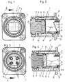
- the plug part 1 is a socket connector part or plug receiving part which is provided for mounting in a through hole in a wall.
- it has a mounting flange 27 arranged on the housing 5, as is known per se in the prior art.
- the sleeve plug part or plug receiving part is in this case the plug part, in which or in the housing of which the female light guides or receiving sleeves for the male light guides are arranged.
- Fig. 1 and 3 show views of this plug part 1, from the direction from which the corresponding male plug part or the plug is inserted.
- Fig. 1 shows the position in which the flap 4, the passage opening 7 completely closes.
- Fig. 2 shows the longitudinal section in this position according to the section line AA.
- Fig. 3 shows a top view like Fig. 1 However, here is the flap 4 folded back, so that the passage opening 7 completely open and the four arranged in this plug part light guide 3 can be seen.
- the attachment and storage of the light guide 3 in the optical fiber carrier 10 is carried out as known per se.
- ferrules which receive the optical fibers 3 are usually arranged at their ends.
- the ferrules can be arranged movably or fixedly in the optical waveguide 10.
- the ferrules and the optical fiber carrier can be designed as known per se as in the prior art.
- Fig. 4 shows a longitudinal section analogous to Fig. 2 however, by the in Fig. 3 shown opening position along the section line AA.
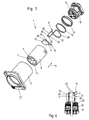
- Fig. 5 shows the individual components of this connector part 1 in an exploded view.
- Fig. 6 To illustrate the operation of the flip-reset spring 17 of this embodiment, the flap return spring 17 supported and mounted on the optical fiber carrier 10 in this embodiment is shown in which the left half of this illustration shows the flap 4 in the fully open position and the right part of FIG Fig. 6 the shutter 4 shows in its closed position. The remaining components of this connector part 1 are omitted in this illustration for the sake of clarity.
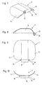
- the Fig. 7 to 10 show still different views of the flap 4 of this embodiment.
- the displacement part 6 is linearly displaceable in this embodiment, mounted along the direction of displacement 13 within the housing 5.
- the sliding directions 13 are conveniently parallel to the longitudinal central axis 21 of the plug part 1 and the housing 5.
- the sliding part 6 is slidably mounted in the concrete embodiment of the plug part 1 on the light guide carrier 10.
- the sealing ring 12 is provided. This is arranged in a direction parallel to the direction of displacement 13 of the sliding part 6 elongated, here annular jacket-shaped guide space 14. Due to the longitudinal extent of this guide space 14, it is possible that the sealing ring 12 shifts, for example, by rolling in the guide space 14 in the respective displacement direction 13, in which the displacement member 6 is moved relative to the light guide carrier 10. By this particular rolling displacement of the sealing ring 12, the frictional forces are primarily reduced.
- sealing ring not only on the concrete in Fig. 2 and 4 particularly good to see place or function can be used. Rather, it is also possible that this sealing ring is arranged between the displacement part 6 and the housing 5, or between the displacement part 6 and another preferably housing-fixed component of the plug part or acts.
- fixed to the housing is generally understood that between the housing-fixed component and the housing no relative movement takes place or can take place.
- the return spring 11 is provided to return the sliding part 6 of the in Fig. 4 shown position in, in Fig. 2 shown position corresponding to the closed position of the flap 4, the return spring 11 is provided.
- This is supported in the concretely shown embodiment of the plug part 1 on the light guide carrier 10, and carries on its opposite side the end face 9 away from the end of the sliding part 6 and is biased in such a way that the sliding part 6 in the in Fig. 2 shown position is pressed.
- this is a coil spring.
- other elastic bodies can be used.
- a support of the return spring 11 on the fiber optic carrier 10 is not absolutely necessary. Rather, a support can also be carried out directly on the housing 5 or on a preferably fixed to the housing connected component. The introduction of force to move the sliding part in the in Fig.
- the actuating element 8 arranged on the displacement part in this exemplary embodiment presses on the in Fig. 4 Dashed lines shown outer contour of the shutter 4, whereby the shutter from the in Fig. 2 shown closed position in the in Fig. 4 shown, fully open position is pivoted.
- the pivot axis 22, by which the closure flap 4 is pivoted, is in this embodiment a part of the flap return spring 17, which is particularly well in the exploded view according to FIG Fig. 5 you can see.
- this flap return spring 17 has two spring legs 23. These are biased towards each other, and act or press in this embodiment, two oppositely disposed inclined surfaces 24 which are provided on the closure flap 4. These inclined surfaces are arranged obliquely or in an angle deviating from 0 ° and 180 ° relative to the spring legs.
- the inclined surfaces 24 are arranged in the embodiment shown on a partially tubular axle guide 25 of the closure flap 4, wherein the pivot axis 22 about which the closure flap 4 is pivotable, is rotatably mounted in this axle guide 25.
- This storage is especially good in Fig. 6 to see.
- the storage and design of the inclined surfaces 24 goes particularly well from the FIGS. 7, 9 and 10 out.
- the pivot axis 22 is formed in the embodiment shown by two, compared to the remaining spring legs 23 angled and here facing each other extensions 26 of the respective spring leg 23. Between the two extensions 26, a gap is provided so that the spring legs 23 can be pressed apart from the inclined surfaces 24.
- the two spring legs 23 of the flap return spring 17 are integrally formed in the illustrated embodiment on a base sheet 28, which serves on the one hand for supporting and securing the flap return spring 17 - here at the light guide 10 and on the other hand can also contribute to the bias or spring action of the spring leg 23.
- any other attachment of the spring leg 23 to the fiber optic support 10 or to other components which are connected to the housing 5 or on the housing 5 itself conceivable.
- it does not necessarily have to be two in the direction of spring leg 23 biased towards each other. With correspondingly arranged inclined surfaces 24 on the closure flap 4, these spring legs 23 can also be biased in a direction pointing away from each other.
- pivot axis 22 is at least partially formed by at least one, preferably angled relative to the spring leg 23, extension 26 of the spring leg.
- This male plug part or plug-in part 2 is that plug part, on or in which or in the housing, the male or protruding light guide 3 are arranged, which are inserted into the female receptacles of the light guide of the socket 1.
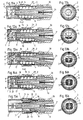
- the Fig. 11a to 15a show longitudinal sections through this plug part 2, wherein in Fig. 11a the closed position of the flap 4 and in Fig. 15a the completely open position of the closure flap 4 or the completely pushed back position of the displacement part 6 is shown. The position according to Fig.
- FIG. 15a is achieved when the male connector part 2 is fully inserted into the socket connector part 1.
- the Fig. 12a to 14a show different intermediate positions.
- the Fig. 11b to 15b show the respective views on the front side 9 of the connector part 2, wherein particularly particularly well the opening degree and the position of the closure flap in the position shown in each case can be seen.
- Fig. 16 again shows an exploded view of this connector part 2
- the Fig. 17 to 20 show different, each indicated in the individual figures sections through an arrangement of displacement part 6, additional sliding part 18 and shutter 4 of the connector part 2.
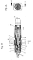
- Die FIGS. 21 and 22 show the flap 4 of this connector part 2 itself. Even if the individual components of the plug part 2 are formed differently than the corresponding components of the previously described connector part 1, so were the same designations and the same reference numerals are still selected for the components that each have the same function.
- a first significant difference forms the on the housing - here inside the housing 5 - relative to the housing 5 linearly displaceably mounted additional sliding part 18 which is linearly displaceable relative to the displacement part 6.
- additional sliding part 18 which is linearly displaceable relative to the displacement part 6.
- the valve return spring 17 acts, which is designed in this connector part 2 as a helical spring. Again, of course, any differently shaped and suitable elastic element can be used. From the flap return spring 17, the displacement part 6 is loaded or biased in the direction away from the additional displacement part 18. By this bias the flap return spring acts 17 also on the flap 4, as will be explained below.
- the closure flap 4 is rotatably mounted in this plug part 2 on the sliding part 6 and here likewise linearly displaceable in an additional guide groove 20 on or in the additional sliding part 18.
- a pair of axle pins 32 arranged opposite the closure flap legs 33 or on the closure flap 4 are predetermined, through which the pivot axis 22 runs.
- the axle journals 32 engage with this plug part 2 in each case in the axle journal receptacles 34 in the arms 35 of the sliding part 6. This is especially good in Fig. 19 to see.
- the axle journals 32 and the axle journal receptacle 34 also ensure that the closure flap 4 is displaced in a linear manner together with the displacement part 6 - in the case of the plug part 2 shown.
- an actuating element 8 is likewise provided in the case of this plug part 2. This is in the concrete example by the particularly good in the Fig. 16 and 17 to 19 such as 21 and 22 achieved to see peg-shaped actuators 8. In the concrete example, these are two pins arranged on the opposite closure flap legs 33 or pointing outwards. Of course, a pin would be sufficient as an actuator 8.
- the actuators 8 of this example are slidably mounted in Vietnamese cabinet, but this does not necessarily have to be so.
- the guide groove 19 along which the displacement part 6 can be displaced against the additional displacement part 18 is arranged orthogonally to the additional guide groove 8 in the case of the specifically shown plug part 2. But this does not necessarily have to be this way. It is also another, angular, that is not parallel arrangement of these two guide grooves 19 and 20 possible.
- Figs. 14a and 15a takes place at a corresponding load on the end face 9 but not only a relative displacement between the sliding part 6 and additional sliding part 18. These two components are rather pushed together into the housing interior. This is done under compression of the return spring 11, even with this plug part 2, this is supported on the fiber optic carrier 10, but what, as already explained above with respect to the connector part 1, not the only possible embodiment.
- the light guides 3 and a part of the light guide carrier 10 pass through the already opened through opening 7, which, as explained below, serves to connect the light guides 3 of the plug part 2 to the light guides 3 arranged in the plug part 1.
- the flap return spring 17 provides for the remaining provision in the in Fig. 11a shown closed position of the closure flap 4 in which the displacement part 6 from the additional sliding part 18 in the direction of displacement 13 and the here also parallel thereto direction of the longitudinal central axis 21 is spaced.
- the flap return spring 17 is advantageously softer or deformed with lower forces than the return spring 11. This is preferably true in general and in particular Plug part 1.
- the closure flap 4 for the reasons already mentioned on rounded areas. In the case of the plug part 2 shown, these are ball surface sections 16. Thus, the closure flap 4 in the closed position according to FIG Fig. 11a and Fig. 20 does not protrude beyond the sliding part 6, it has centrally a flattened area 31st
- the concrete plug part 2 predetermined by the axle 32 pivot axis 22 of the flap 4, in particular in the closed position of the flap 4, but here in all other positions relatively close to the longitudinal center axis 21. It also forms the center of the spherical surface sections 16, which leads to a space-optimized pivoting of the flap 4.
- the distance between the longitudinal central axis 21 of the housing 5 and the sliding part 6 and the pivot axis 22 about which the closure flap 4 is pivotable less than 10%, preferably less than 5%, of the maximum outer diameter of the sliding part ,
- the longitudinal central axis 21 and in most cases also the pivoting axis 22 are not actually physically present, continuous axes.
- the distance is the smallest distance between the longitudinal central axis 21 and pivot axis 22.
- the pivot axis 22 about which the closure flap 4 is pivotable, eccentric with respect to a longitudinal central axis 21 of the housing 5 and des Displacement parts 6 is arranged.
- Eccentric means that the pivot axis 22 does not intersect the longitudinal center axis 21, but is just arranged with a, although preferably small distance to this.
- housing end 30, which can be screwed in the connector part 2 shown on the housing 5. This is favorable in terms of a simple assembly of the plug part 2, but also not mandatory.
- the housing 5 may also have an integrally formed finish.
- a known per se locking sleeve 29 is provided on the plug part 2 also. This serves to lock the plug part 2 with the plug part 1 when they are completely pushed into each other and connected to prevent accidental release of this connection.
- the locking sleeve 29 and its latching on the plug part 1 can be carried out as known in the prior art, so that further explanations on this unnecessary.
- Fig. 23 now shows a partially sectioned view of the fully interconnected connector parts 1 and 2, in this position, the respective optical fiber 3 of the two connector parts are connected to each other so that light signals can be transmitted.
- Fig. 24 shows the section line FF the Fig. 23 , In the illustrated, contacted position, the two end faces 9 of the respective displacement parts 6 abut each other. The respective closing flaps 4 are fully opened, the sliding parts 6 are each inserted maximally into the respective housing 5, the light guide carrier 10 of the male plug part 2, together with its light guide, has penetrated the through openings 7 in both displacement parts 6, so that the light guides 3 of these two plug parts 1 and 2 vis-à-vis have been brought into contact with each other, as is well known.
- the light guide 3 of the connector part 1 can also be arranged fixed in this.
- the locking sleeve 29 To remove the plug part 2 from the plug part 1, the locking sleeve 29 must be operated accordingly, so that the predetermined connection between them is solved between the two plug parts, then the plug part 2 can be pulled out of the plug part 1, whereby the sliding parts 6 and the respective flaps 4 of the respective flap return springs 17 and the return springs 11 back in their closed positions in accordance with Fig. 11a and Fig. 1 and 2 be reset.
- the plug part 2 in the plug part 1 first meet the two end faces 9 of the sliding parts 6 to each other, causing them to move back and the shutter 4 are opened automatically, which by further insertion of the plug part 2 in the plug part 1 again in Fig. 23 shown connection position is achieved.
Landscapes
- Physics & Mathematics (AREA)
- General Physics & Mathematics (AREA)
- Optics & Photonics (AREA)
- Mechanical Coupling Of Light Guides (AREA)
- Connector Housings Or Holding Contact Members (AREA)
Claims (15)
- Partie d'enfichage (1) pour une connexion optique par enfichage en vue de relier des guides optiques (3) entre eux, la partie d'enfichage (1) étant munie d'au moins un volet de fermeture (4) pivotant et d'un boîtier (5) et d'au moins un guide optique (3) disposé à l'intérieur du boîtier (5), et au moins une pièce coulissante (6) étant logée sur le boîtier (5), en particulier à l'intérieur du boîtier (5), de façon coulissante par rapport au boîtier (5), notamment de façon linéaire, la pièce coulissante (6) étant munie d'au moins une ouverture de passage (7) et la partie d'enfichage (1) étant munie d'au moins un organe d'actionnement (8) pour faire pivoter le volet de fermeture (4), l'organe d'actionnement (8) faisant pivoter le volet de fermeture (4) lors du coulissement de la pièce coulissante (6), l'ouverture de passage (7) dans la pièce coulissante (6) étant fermée, dans au moins une position fermée du volet de fermeture (4), par le volet de fermeture (4), de préférence complètement, caractérisée en ce qu'au moins une bague d'étanchéité (12) est disposée entre la pièce coulissante (6) et le boîtier (5) ou entre la pièce coulissante (6) et un autre constituant de la partie d'enfichage (1), de préférence fixé au boîtier, de préférence un support de guides optiques (10), la bague d'étanchéité (12) étant disposée dans un espace de guidage (14) qui s'étend longitudinalement parallèlement à une direction de coulissement (13) de la pièce coulissante (6), de préférence en forme d'enveloppe annulaire, et la bague d'étanchéité (12) de la partie coulissante (6) étant logée dans l'espace de guidage (14) de manière à pouvoir coulisser dans la direction de coulissement (13).
- Partie d'enfichage (1) selon la revendication 1, caractérisée en ce que la pièce coulissante (6) est munie d'une face frontale (9) qui, de préférence au moins dans la position fermée du volet de fermeture (4), est disposée sur un côté extérieur de la pièce coulissante (6) opposé au guide optique (3), et l'ouverture de passage (7) est une ouverture dans la face frontale (9).
- Partie d'enfichage (1) selon la revendication 1 ou 2, caractérisée en ce qu'au moins deux, de préférence au moins trois ou au moins quatre, guides optiques (3) sont disposés à l'intérieur du boîtier (5).
- Partie d'enfichage (1) selon la revendication 3, caractérisée en ce que les guides optiques (3) sont maintenus, de préférence ensemble, dans un support de guides optiques (10) qui est disposé à l'intérieur du boîtier (5), de préférence non coulissant par rapport au boîtier (5).
- Partie d'enfichage (1) selon la revendication 3 ou 4, caractérisée en ce que, dans au moins une position de la pièce coulissante (6) dans laquelle le volet de fermeture (4) découvre, de préférence complètement, la fenêtre de passage (7), les guides optiques (3), de préférence tous, disposés à l'intérieur du boîtier (5) de la partie d'enfichage (1) sont guidés ensemble à travers l'ouverture de passage (7), de préférence le support de guides optiques (10) disposé à l'intérieur du boîtier (5) de la partie d'enfichage (1) est guidé à travers l'ouverture de passage (7), ou les guides optiques (3), de préférence tous, d'une autre partie d'enfichage (2) de la connexion par enfichage sont guidés ensemble à travers l'ouverture de passage (7), et/ou un support de guides optiques (10) d'une autre partie d'enfichage (2) de la connexion enfichable est guidé à travers l'ouverture de passage (7).
- Partie d'enfichage (1) selon l'une des revendications 1 à 5, caractérisée en ce qu'elle est munie d'au moins un ressort de rappel (11) pour la pièce coulissante (6), de préférence en appui sur le boîtier (5) ou sur un support de guides optiques (10), contre l'action de force duquel la pièce coulissante (6) peut être coulissée de sa position dans laquelle le volet de fermeture (4) ferme l'ouverture de passage (7), en direction du ou des guides optiques (3).
- Partie d'enfichage (1) selon l'une des revendications 1 à 6, caractérisée en ce que la bague d'étanchéité (12) de la pièce coulissante (6) est logée coulissante dans l'espace de guidage (14) de manière à pouvoir rouler dans la direction de coulissement (13).
- Partie d'enfichage (1) selon l'une des revendications 1 à 7, caractérisée en ce que le volet de fermeture (4) est muni, au moins par sections, d'un contour extérieur courbé, de préférence sous la forme d'une section d'enveloppe tubulaire (15) ou d'une section d'enveloppe cylindrique ou d'une surface sphérique (16).
- Partie d'enfichage (1) selon l'une des revendications 1 à 8, caractérisée en ce qu'il est prévu un ressort de rappel de volet (17) qui agit sur le volet de fermeture (4) dans la direction de sa position fermée, de préférence ramène le volet de fermeture (4) en position fermée lorsque la pièce coulissante (6) est libérée des forces agissant de l'extérieur, et/ou en ce que la partie d'enfichage (1) est munie d'au moins une pièce coulissante supplémentaire (18) qui est logée sur le boîtier (5), en particulier à l'intérieur du boîtier (5), de façon coulissante par rapport au boîtier (5), notamment de façon linéaire, et la pièce coulissante (6) est logée coulissante par rapport à la pièce coulissante supplémentaire (18), de préférence de manière linéaire.
- Pièce d'enfichage (1) selon la revendication 9, caractérisée en ce que le ressort de rappel de volet (17) agit, de préférence est, entre la pièce coulissante (6) et la pièce coulissante supplémentaire (18), et de préférence et de préférence sollicite la pièce coulissante (6) dans la direction opposée à la pièce coulissante supplémentaire (18).
- Pièce d'enfichage (1) selon la revendication 9 ou 10, caractérisée en ce que la pièce coulissante (6) est logée coulissante par rapport à la pièce coulissante supplémentaire (18), de préférence de façon linéaire, dans au moins une rainure de guidage (19), de préférence dans deux rainures situées à l'opposé l'une de l'autre, dans ou sur la pièce coulissante supplémentaire (18), et/ou en ce que le volet de fermeture (4) est logé rotatif sur la pièce coulissante (6) et coulissant, de préférence de façon linéaire, dans une rainure de guidage supplémentaire (20) sur ou dans la pièce coulissante supplémentaire (18).
- Pièce d'enfichage (1) selon l'une des revendications 1 à 11, caractérisée en ce que la distance entre un axe central longitudinal (21) du boîtier (5) ou de la pièce coulissante (6) et un axe de pivotement (22) autour duquel peut pivoter le volet de fermeture (4), est inférieure à 10 %, de préférence inférieur à 5 %, du diamètre extérieur maximal de la pièce coulissante, ou en ce qu'un axe de pivotement (22), autour duquel le volet de fermeture (4) peut pivoter, est disposé de manière excentrée par rapport à un axe central longitudinal (21) du boîtier (5) ou de la pièce coulissante (6).
- Pièce d'enfichage (1) selon la revendication 9, caractérisée en ce que le ressort de rappel de volet (17) est muni d'au moins une branche de ressort (23) précontrainte, de préférence d'au moins deux branches de ressort précontraintes en direction l'une de l'autre ou à l'opposé l'une de l'autre, et le volet de fermeture (4), qui est de préférence disposé et/ou mis sous tension entre les branches de ressort (23), est muni d'au moins une, de préférence deux, surface(s) inclinée(s) (24), la ou les branches de ressort (23) agissant ou appuyant sur la ou les surfaces inclinées (24) du volet de fermeture (4) pour ramener le volet de fermeture (4) dans la direction de sa position fermée.
- Pièce d'enfichage (1) selon la revendication 13, caractérisée en ce que la ou les surfaces inclinées (24) sont disposées sur un guide axial (25) par endroit tubulaire du volet de fermeture (4), un axe de pivotement (22), autour duquel le volet de fermeture (4) peut pivoter, étant logé pivotant dans ce guide axial (25).
- Connexion enfichable avec une partie enfichable (1), de préférence avec au moins deux parties enfichables (1) selon l'une des revendications 1 à 14.
Applications Claiming Priority (1)
| Application Number | Priority Date | Filing Date | Title |
|---|---|---|---|
| DE102008033232A DE102008033232A1 (de) | 2008-07-15 | 2008-07-15 | Steckerteil für eine optische Steckverbindung |
Publications (2)
| Publication Number | Publication Date |
|---|---|
| EP2146232A1 EP2146232A1 (fr) | 2010-01-20 |
| EP2146232B1 true EP2146232B1 (fr) | 2018-12-26 |
Family
ID=41016795
Family Applications (1)
| Application Number | Title | Priority Date | Filing Date |
|---|---|---|---|
| EP09008787.5A Active EP2146232B1 (fr) | 2008-07-15 | 2009-07-04 | Connecteur pour un raccordement optique |
Country Status (5)
| Country | Link |
|---|---|
| US (1) | US7857524B2 (fr) |
| EP (1) | EP2146232B1 (fr) |
| CN (1) | CN101630043B (fr) |
| DE (1) | DE102008033232A1 (fr) |
| TR (1) | TR201903876T4 (fr) |
Families Citing this family (16)
| Publication number | Priority date | Publication date | Assignee | Title |
|---|---|---|---|---|
| JP5443201B2 (ja) * | 2010-02-22 | 2014-03-19 | 三和電気工業株式会社 | シャッタ付き光コネクタプラグ |
| JP5623621B2 (ja) * | 2010-03-19 | 2014-11-12 | コーニング インコーポレイテッド | 位置決め可能なカバー付き光ファイバインターフェース装置 |
| FR2975231B1 (fr) * | 2011-05-10 | 2014-08-22 | Souriau | Ensemble de connexion etanche |
| CN103018844B (zh) * | 2011-09-23 | 2014-10-15 | 泰科电子(上海)有限公司 | 光纤连接器插头 |
| CN103018843B (zh) * | 2011-09-23 | 2015-05-20 | 泰科电子(上海)有限公司 | 光纤连接器插头 |
| DE102011085034A1 (de) * | 2011-10-21 | 2013-04-25 | Tesa Se | Klebemasse insbesondere zur Kapselung einer elektronischen Anordnung |
| DE102013008266B4 (de) | 2013-05-15 | 2025-12-11 | Neutrik Ag | Steckerteil |
| USD755720S1 (en) * | 2013-10-14 | 2016-05-10 | Neutrik Ag | Connector |
| DE202015101396U1 (de) * | 2015-03-18 | 2015-04-14 | Neutrik Ag | Steckerteil |
| DE102016101254A1 (de) * | 2016-01-25 | 2017-07-27 | Neutrik Ag | Verbinder |
| CN109690376B (zh) | 2016-09-12 | 2020-11-06 | 住友电气工业株式会社 | 光连接器、多连光连接器及光连接构造 |
| USD840341S1 (en) | 2017-06-20 | 2019-02-12 | Amphenol Corporation | Cable connector |
| US10186804B2 (en) | 2017-06-20 | 2019-01-22 | Amphenol Corporation | Cable connector with backshell locking |
| USD839193S1 (en) | 2017-06-20 | 2019-01-29 | Amphenol Corporation | Cable connector |
| TWI727144B (zh) * | 2018-02-14 | 2021-05-11 | 普泰光電股份有限公司 | 具有防水功能的光纖連接器 |
| CN110600917A (zh) * | 2018-06-30 | 2019-12-20 | 中航光电科技股份有限公司 | 插头及连接器 |
Family Cites Families (21)
| Publication number | Priority date | Publication date | Assignee | Title |
|---|---|---|---|---|
| US6004147A (en) * | 1993-09-02 | 1999-12-21 | State Of Israel, Ministry Of Defence, Etc. | Line terminal particularly signal transmitter, connector assembly |
| EP0893716A1 (fr) | 1997-07-21 | 1999-01-27 | Diamond S.A. | Douille en particulier pour une connexion optique et connecteur pour fibres optiques |
| US6081647A (en) * | 1998-01-05 | 2000-06-27 | Molex Incorporated | Fiber optic connector receptacle |
| US6108482A (en) | 1998-01-14 | 2000-08-22 | Molex Incorporated | Fiber optic connector receptacle |
| US6079881A (en) * | 1998-04-08 | 2000-06-27 | Molex Incorporated | Fiber optic connector receptacle assembly |
| JP3207159B2 (ja) * | 1998-06-05 | 2001-09-10 | ヒロセ電機株式会社 | シャッタ付き光コネクタ |
| EP1128199B8 (fr) | 1998-07-27 | 2003-07-02 | Huber & Suhner Ag | Prise de connexion pour des guides d'ondes lumineuses |
| EP1037078A1 (fr) | 1999-03-08 | 2000-09-20 | Diamond SA | Elément de protection pour couvrir une surface émettant de la lumière dans un composant optique, en particulier dans un connecteur optique |
| DE10108783A1 (de) * | 2001-02-23 | 2002-09-05 | Delphi Tech Inc | Steckverbinder für Lichtleiter |
| DE50105690D1 (de) * | 2001-06-29 | 2005-04-28 | Diamond Sa | Buchsenteil und Steckerteil für eine optische Steckverbindung |
| EP1331499A1 (fr) | 2002-01-25 | 2003-07-30 | Diamond S.A. | Connecteur optique |
| JP4028354B2 (ja) * | 2002-10-01 | 2007-12-26 | 株式会社フジクラ | シャッター付き光コネクタ |
| US7144163B2 (en) * | 2003-01-27 | 2006-12-05 | Fujikura Ltd. | Optical connector with shutter, shutter unit, and inner piece |
| JP4328711B2 (ja) * | 2003-12-05 | 2009-09-09 | 株式会社精工技研 | 光コネクタプラグ及び光コネクタ |
| JP4328712B2 (ja) * | 2004-03-10 | 2009-09-09 | 株式会社精工技研 | 光コネクタプラグ及び光コネクタ |
| JP4084764B2 (ja) * | 2004-03-12 | 2008-04-30 | ホシデン株式会社 | シャッター付き光コネクタ |
| DE102004025512A1 (de) | 2004-05-21 | 2005-12-15 | Neutrik Aktiengesellschaft | Einrichtung für eine optische Steckverbindung |
| JP4354338B2 (ja) * | 2004-06-07 | 2009-10-28 | タイコエレクトロニクスアンプ株式会社 | 多心光コネクタ組立体 |
| DE602005002114T2 (de) * | 2004-11-29 | 2008-04-10 | Seikoh Giken Co., Ltd., Matsudo | Optischer Stecker-Stift und optischer Verbinder |
| US7284912B2 (en) * | 2005-01-12 | 2007-10-23 | Illum Technologies, Inc. | Multi fiber optical interconnect system, with push—push type insertion/withdrawal mechanism, MT-type connector and shuttered adapter and method for using same |
| JP4832414B2 (ja) * | 2006-12-20 | 2011-12-07 | 本多通信工業株式会社 | 遮光部材付光コネクタプラグ |
-
2008
- 2008-07-15 DE DE102008033232A patent/DE102008033232A1/de not_active Ceased
-
2009
- 2009-07-04 TR TR2019/03876T patent/TR201903876T4/tr unknown
- 2009-07-04 EP EP09008787.5A patent/EP2146232B1/fr active Active
- 2009-07-10 US US12/500,746 patent/US7857524B2/en active Active
- 2009-07-14 CN CN200910152106.2A patent/CN101630043B/zh active Active
Non-Patent Citations (1)
| Title |
|---|
| None * |
Also Published As
| Publication number | Publication date |
|---|---|
| TR201903876T4 (tr) | 2019-04-22 |
| US20100014812A1 (en) | 2010-01-21 |
| US7857524B2 (en) | 2010-12-28 |
| EP2146232A1 (fr) | 2010-01-20 |
| CN101630043A (zh) | 2010-01-20 |
| CN101630043B (zh) | 2014-12-17 |
| DE102008033232A1 (de) | 2010-01-21 |
Similar Documents
| Publication | Publication Date | Title |
|---|---|---|
| EP2146232B1 (fr) | Connecteur pour un raccordement optique | |
| EP3420168B1 (fr) | Entraînement de bras d'actionnement | |
| EP0599784B1 (fr) | Douille pour un terminal de connexion à fibre optique | |
| DE102014206825B4 (de) | Scharniereinrichtung für eine KFZ- Tür | |
| EP2594473A1 (fr) | Dispositif à dérailleur pour un agencement de vitesses de vélo, notamment dispositif à dérailleur arrière | |
| DE19707041A1 (de) | Schnellverbindevorrichtung | |
| DE102018105998B3 (de) | Kupplungssystem | |
| DE102020111986A1 (de) | Spindelantrieb für ein Verschlusselement eines Kraftfahrzeugs | |
| EP1674779A1 (fr) | Raccord pour tuyau | |
| WO2012052351A1 (fr) | Dispositif d'absorption du bruit | |
| EP4091218B1 (fr) | Pièce de raccordement pour un système de raccordement par enfichage | |
| EP2870100A1 (fr) | Dispositif d'assemblage articulé | |
| EP3420167B1 (fr) | Entraînement de bras d'actionnement | |
| EP3025069B1 (fr) | Dispositif permettant de déclencher un ressort à gaz | |
| EP3625416B1 (fr) | Ensemble ressort pour un support de volet | |
| WO2019185796A1 (fr) | Bloc de jonction | |
| EP3057469B1 (fr) | Ressort à gas avec un dispositif permettant de déclencher le ressort à gaz | |
| DE10208704B4 (de) | Kontaktanordnung mit zueinander längsbeweglich geführten Kontaktstücken und Rollenkontakt zur Kontaktgabe in einer solchen Kontaktanordnung | |
| EP3819513B1 (fr) | Palier lisse, dispositif d'équipement pourvu d'au moins un palier lisse et dispositif d'équipement pourvu d'au moins un palier logé rotatif | |
| EP1072917A1 (fr) | Connecteur avec clapet de protection pour connexion à fibre optique | |
| EP2362045B1 (fr) | Porte pour une armoire électrique | |
| WO2020077375A1 (fr) | Unité de charge pour charger un véhicule | |
| DE102022124179A1 (de) | Luftleitvorrichtung einer Kraftfahrzeugkarosserie eines Kraftfahrzeugs | |
| DE10236315B4 (de) | Armlehne, insbesondere für ein Kraftfahrzeug | |
| DE102013012190A1 (de) | Vorrichtung zum Auslösen einer Gasfeder |
Legal Events
| Date | Code | Title | Description |
|---|---|---|---|
| PUAI | Public reference made under article 153(3) epc to a published international application that has entered the european phase |
Free format text: ORIGINAL CODE: 0009012 |
|
| AK | Designated contracting states |
Kind code of ref document: A1 Designated state(s): AT BE BG CH CY CZ DE DK EE ES FI FR GB GR HR HU IE IS IT LI LT LU LV MC MK MT NL NO PL PT RO SE SI SK SM TR |
|
| AX | Request for extension of the european patent |
Extension state: AL BA RS |
|
| 17P | Request for examination filed |
Effective date: 20100423 |
|
| 17Q | First examination report despatched |
Effective date: 20100607 |
|
| STAA | Information on the status of an ep patent application or granted ep patent |
Free format text: STATUS: EXAMINATION IS IN PROGRESS |
|
| RAP1 | Party data changed (applicant data changed or rights of an application transferred) |
Owner name: NEUTRIK AG |
|
| GRAP | Despatch of communication of intention to grant a patent |
Free format text: ORIGINAL CODE: EPIDOSNIGR1 |
|
| STAA | Information on the status of an ep patent application or granted ep patent |
Free format text: STATUS: GRANT OF PATENT IS INTENDED |
|
| RIC1 | Information provided on ipc code assigned before grant |
Ipc: G02B 6/42 20060101ALN20180731BHEP Ipc: G02B 6/38 20060101AFI20180731BHEP |
|
| INTG | Intention to grant announced |
Effective date: 20180904 |
|
| GRAS | Grant fee paid |
Free format text: ORIGINAL CODE: EPIDOSNIGR3 |
|
| GRAA | (expected) grant |
Free format text: ORIGINAL CODE: 0009210 |
|
| STAA | Information on the status of an ep patent application or granted ep patent |
Free format text: STATUS: THE PATENT HAS BEEN GRANTED |
|
| AK | Designated contracting states |
Kind code of ref document: B1 Designated state(s): AT BE BG CH CY CZ DE DK EE ES FI FR GB GR HR HU IE IS IT LI LT LU LV MC MK MT NL NO PL PT RO SE SI SK SM TR |
|
| REG | Reference to a national code |
Ref country code: GB Ref legal event code: FG4D Free format text: NOT ENGLISH |
|
| REG | Reference to a national code |
Ref country code: CH Ref legal event code: EP |
|
| REG | Reference to a national code |
Ref country code: AT Ref legal event code: REF Ref document number: 1082198 Country of ref document: AT Kind code of ref document: T Effective date: 20190115 |
|
| REG | Reference to a national code |
Ref country code: DE Ref legal event code: R096 Ref document number: 502009015522 Country of ref document: DE |
|
| REG | Reference to a national code |
Ref country code: IE Ref legal event code: FG4D Free format text: LANGUAGE OF EP DOCUMENT: GERMAN |
|
| REG | Reference to a national code |
Ref country code: CH Ref legal event code: NV Representative=s name: ALDO ROEMPLER PATENTANWALT, CH |
|
| PG25 | Lapsed in a contracting state [announced via postgrant information from national office to epo] |
Ref country code: FI Free format text: LAPSE BECAUSE OF FAILURE TO SUBMIT A TRANSLATION OF THE DESCRIPTION OR TO PAY THE FEE WITHIN THE PRESCRIBED TIME-LIMIT Effective date: 20181226 Ref country code: NO Free format text: LAPSE BECAUSE OF FAILURE TO SUBMIT A TRANSLATION OF THE DESCRIPTION OR TO PAY THE FEE WITHIN THE PRESCRIBED TIME-LIMIT Effective date: 20190326 Ref country code: LV Free format text: LAPSE BECAUSE OF FAILURE TO SUBMIT A TRANSLATION OF THE DESCRIPTION OR TO PAY THE FEE WITHIN THE PRESCRIBED TIME-LIMIT Effective date: 20181226 Ref country code: LT Free format text: LAPSE BECAUSE OF FAILURE TO SUBMIT A TRANSLATION OF THE DESCRIPTION OR TO PAY THE FEE WITHIN THE PRESCRIBED TIME-LIMIT Effective date: 20181226 Ref country code: BG Free format text: LAPSE BECAUSE OF FAILURE TO SUBMIT A TRANSLATION OF THE DESCRIPTION OR TO PAY THE FEE WITHIN THE PRESCRIBED TIME-LIMIT Effective date: 20190326 Ref country code: HR Free format text: LAPSE BECAUSE OF FAILURE TO SUBMIT A TRANSLATION OF THE DESCRIPTION OR TO PAY THE FEE WITHIN THE PRESCRIBED TIME-LIMIT Effective date: 20181226 |
|
| REG | Reference to a national code |
Ref country code: NL Ref legal event code: MP Effective date: 20181226 |
|
| REG | Reference to a national code |
Ref country code: LT Ref legal event code: MG4D |
|
| PG25 | Lapsed in a contracting state [announced via postgrant information from national office to epo] |
Ref country code: SE Free format text: LAPSE BECAUSE OF FAILURE TO SUBMIT A TRANSLATION OF THE DESCRIPTION OR TO PAY THE FEE WITHIN THE PRESCRIBED TIME-LIMIT Effective date: 20181226 Ref country code: GR Free format text: LAPSE BECAUSE OF FAILURE TO SUBMIT A TRANSLATION OF THE DESCRIPTION OR TO PAY THE FEE WITHIN THE PRESCRIBED TIME-LIMIT Effective date: 20190327 |
|
| PG25 | Lapsed in a contracting state [announced via postgrant information from national office to epo] |
Ref country code: NL Free format text: LAPSE BECAUSE OF FAILURE TO SUBMIT A TRANSLATION OF THE DESCRIPTION OR TO PAY THE FEE WITHIN THE PRESCRIBED TIME-LIMIT Effective date: 20181226 |
|
| PG25 | Lapsed in a contracting state [announced via postgrant information from national office to epo] |
Ref country code: CZ Free format text: LAPSE BECAUSE OF FAILURE TO SUBMIT A TRANSLATION OF THE DESCRIPTION OR TO PAY THE FEE WITHIN THE PRESCRIBED TIME-LIMIT Effective date: 20181226 Ref country code: IT Free format text: LAPSE BECAUSE OF FAILURE TO SUBMIT A TRANSLATION OF THE DESCRIPTION OR TO PAY THE FEE WITHIN THE PRESCRIBED TIME-LIMIT Effective date: 20181226 Ref country code: PL Free format text: LAPSE BECAUSE OF FAILURE TO SUBMIT A TRANSLATION OF THE DESCRIPTION OR TO PAY THE FEE WITHIN THE PRESCRIBED TIME-LIMIT Effective date: 20181226 Ref country code: ES Free format text: LAPSE BECAUSE OF FAILURE TO SUBMIT A TRANSLATION OF THE DESCRIPTION OR TO PAY THE FEE WITHIN THE PRESCRIBED TIME-LIMIT Effective date: 20181226 Ref country code: PT Free format text: LAPSE BECAUSE OF FAILURE TO SUBMIT A TRANSLATION OF THE DESCRIPTION OR TO PAY THE FEE WITHIN THE PRESCRIBED TIME-LIMIT Effective date: 20190426 |
|
| PG25 | Lapsed in a contracting state [announced via postgrant information from national office to epo] |
Ref country code: EE Free format text: LAPSE BECAUSE OF FAILURE TO SUBMIT A TRANSLATION OF THE DESCRIPTION OR TO PAY THE FEE WITHIN THE PRESCRIBED TIME-LIMIT Effective date: 20181226 Ref country code: SM Free format text: LAPSE BECAUSE OF FAILURE TO SUBMIT A TRANSLATION OF THE DESCRIPTION OR TO PAY THE FEE WITHIN THE PRESCRIBED TIME-LIMIT Effective date: 20181226 Ref country code: RO Free format text: LAPSE BECAUSE OF FAILURE TO SUBMIT A TRANSLATION OF THE DESCRIPTION OR TO PAY THE FEE WITHIN THE PRESCRIBED TIME-LIMIT Effective date: 20181226 Ref country code: IS Free format text: LAPSE BECAUSE OF FAILURE TO SUBMIT A TRANSLATION OF THE DESCRIPTION OR TO PAY THE FEE WITHIN THE PRESCRIBED TIME-LIMIT Effective date: 20190426 Ref country code: SK Free format text: LAPSE BECAUSE OF FAILURE TO SUBMIT A TRANSLATION OF THE DESCRIPTION OR TO PAY THE FEE WITHIN THE PRESCRIBED TIME-LIMIT Effective date: 20181226 |
|
| REG | Reference to a national code |
Ref country code: DE Ref legal event code: R097 Ref document number: 502009015522 Country of ref document: DE |
|
| PG25 | Lapsed in a contracting state [announced via postgrant information from national office to epo] |
Ref country code: DK Free format text: LAPSE BECAUSE OF FAILURE TO SUBMIT A TRANSLATION OF THE DESCRIPTION OR TO PAY THE FEE WITHIN THE PRESCRIBED TIME-LIMIT Effective date: 20181226 |
|
| PLBE | No opposition filed within time limit |
Free format text: ORIGINAL CODE: 0009261 |
|
| STAA | Information on the status of an ep patent application or granted ep patent |
Free format text: STATUS: NO OPPOSITION FILED WITHIN TIME LIMIT |
|
| REG | Reference to a national code |
Ref country code: CH Ref legal event code: NV Representative=s name: ABP PATENT NETWORK AG, CH |
|
| 26N | No opposition filed |
Effective date: 20190927 |
|
| REG | Reference to a national code |
Ref country code: DE Ref legal event code: R082 Ref document number: 502009015522 Country of ref document: DE Representative=s name: KAMINSKI HARMANN PATENTANWAELTE AG, LI Ref country code: DE Ref legal event code: R082 Ref document number: 502009015522 Country of ref document: DE Ref country code: DE Ref legal event code: R082 Ref document number: 502009015522 Country of ref document: DE Representative=s name: ABP BURGER RECHTSANWALTSGESELLSCHAFT MBH, DE |
|
| PG25 | Lapsed in a contracting state [announced via postgrant information from national office to epo] |
Ref country code: MC Free format text: LAPSE BECAUSE OF FAILURE TO SUBMIT A TRANSLATION OF THE DESCRIPTION OR TO PAY THE FEE WITHIN THE PRESCRIBED TIME-LIMIT Effective date: 20181226 Ref country code: SI Free format text: LAPSE BECAUSE OF FAILURE TO SUBMIT A TRANSLATION OF THE DESCRIPTION OR TO PAY THE FEE WITHIN THE PRESCRIBED TIME-LIMIT Effective date: 20181226 |
|
| REG | Reference to a national code |
Ref country code: BE Ref legal event code: MM Effective date: 20190731 |
|
| PG25 | Lapsed in a contracting state [announced via postgrant information from national office to epo] |
Ref country code: LU Free format text: LAPSE BECAUSE OF NON-PAYMENT OF DUE FEES Effective date: 20190704 Ref country code: BE Free format text: LAPSE BECAUSE OF NON-PAYMENT OF DUE FEES Effective date: 20190731 |
|
| PG25 | Lapsed in a contracting state [announced via postgrant information from national office to epo] |
Ref country code: IE Free format text: LAPSE BECAUSE OF NON-PAYMENT OF DUE FEES Effective date: 20190704 |
|
| PG25 | Lapsed in a contracting state [announced via postgrant information from national office to epo] |
Ref country code: CY Free format text: LAPSE BECAUSE OF FAILURE TO SUBMIT A TRANSLATION OF THE DESCRIPTION OR TO PAY THE FEE WITHIN THE PRESCRIBED TIME-LIMIT Effective date: 20181226 |
|
| PG25 | Lapsed in a contracting state [announced via postgrant information from national office to epo] |
Ref country code: MT Free format text: LAPSE BECAUSE OF FAILURE TO SUBMIT A TRANSLATION OF THE DESCRIPTION OR TO PAY THE FEE WITHIN THE PRESCRIBED TIME-LIMIT Effective date: 20181226 Ref country code: HU Free format text: LAPSE BECAUSE OF FAILURE TO SUBMIT A TRANSLATION OF THE DESCRIPTION OR TO PAY THE FEE WITHIN THE PRESCRIBED TIME-LIMIT; INVALID AB INITIO Effective date: 20090704 |
|
| PGFP | Annual fee paid to national office [announced via postgrant information from national office to epo] |
Ref country code: FR Payment date: 20210607 Year of fee payment: 13 |
|
| PGFP | Annual fee paid to national office [announced via postgrant information from national office to epo] |
Ref country code: TR Payment date: 20210608 Year of fee payment: 13 |
|
| PGFP | Annual fee paid to national office [announced via postgrant information from national office to epo] |
Ref country code: AT Payment date: 20210608 Year of fee payment: 13 |
|
| PG25 | Lapsed in a contracting state [announced via postgrant information from national office to epo] |
Ref country code: MK Free format text: LAPSE BECAUSE OF FAILURE TO SUBMIT A TRANSLATION OF THE DESCRIPTION OR TO PAY THE FEE WITHIN THE PRESCRIBED TIME-LIMIT Effective date: 20181226 |
|
| REG | Reference to a national code |
Ref country code: DE Ref legal event code: R082 Ref document number: 502009015522 Country of ref document: DE Representative=s name: KAMINSKI HARMANN PATENTANWAELTE AG, LI Ref country code: DE Ref legal event code: R082 Ref document number: 502009015522 Country of ref document: DE |
|
| REG | Reference to a national code |
Ref country code: DE Ref legal event code: R082 Ref document number: 502009015522 Country of ref document: DE Representative=s name: KAMINSKI HARMANN PATENTANWAELTE AG, LI |
|
| REG | Reference to a national code |
Ref country code: AT Ref legal event code: MM01 Ref document number: 1082198 Country of ref document: AT Kind code of ref document: T Effective date: 20220704 |
|
| PG25 | Lapsed in a contracting state [announced via postgrant information from national office to epo] |
Ref country code: FR Free format text: LAPSE BECAUSE OF NON-PAYMENT OF DUE FEES Effective date: 20220731 Ref country code: AT Free format text: LAPSE BECAUSE OF NON-PAYMENT OF DUE FEES Effective date: 20220704 |
|
| PG25 | Lapsed in a contracting state [announced via postgrant information from national office to epo] |
Ref country code: TR Free format text: LAPSE BECAUSE OF NON-PAYMENT OF DUE FEES Effective date: 20220704 |
|
| PGFP | Annual fee paid to national office [announced via postgrant information from national office to epo] |
Ref country code: DE Payment date: 20250722 Year of fee payment: 17 |
|
| PGFP | Annual fee paid to national office [announced via postgrant information from national office to epo] |
Ref country code: GB Payment date: 20250722 Year of fee payment: 17 |
|
| PGFP | Annual fee paid to national office [announced via postgrant information from national office to epo] |
Ref country code: CH Payment date: 20250801 Year of fee payment: 17 |