EP2146254B1 - Druckmaschine und Verfahren zum Betreiben einer Druckmaschine - Google Patents
Druckmaschine und Verfahren zum Betreiben einer Druckmaschine Download PDFInfo
- Publication number
- EP2146254B1 EP2146254B1 EP09162211.8A EP09162211A EP2146254B1 EP 2146254 B1 EP2146254 B1 EP 2146254B1 EP 09162211 A EP09162211 A EP 09162211A EP 2146254 B1 EP2146254 B1 EP 2146254B1
- Authority
- EP
- European Patent Office
- Prior art keywords
- media
- air knife
- roll
- orifice
- fuse
- Prior art date
- Legal status (The legal status is an assumption and is not a legal conclusion. Google has not performed a legal analysis and makes no representation as to the accuracy of the status listed.)
- Active
Links
- 238000000034 method Methods 0.000 title claims description 26
- 238000005457 optimization Methods 0.000 claims description 27
- 230000004044 response Effects 0.000 claims description 9
- 230000009471 action Effects 0.000 description 9
- 230000001276 controlling effect Effects 0.000 description 9
- 238000003384 imaging method Methods 0.000 description 9
- 239000000463 material Substances 0.000 description 8
- 238000003860 storage Methods 0.000 description 8
- 238000011161 development Methods 0.000 description 6
- 239000000843 powder Substances 0.000 description 6
- 238000012546 transfer Methods 0.000 description 6
- 239000002245 particle Substances 0.000 description 5
- 108091008695 photoreceptors Proteins 0.000 description 5
- 238000012545 processing Methods 0.000 description 5
- RYGMFSIKBFXOCR-UHFFFAOYSA-N Copper Chemical compound [Cu] RYGMFSIKBFXOCR-UHFFFAOYSA-N 0.000 description 4
- 230000006870 function Effects 0.000 description 4
- 230000003287 optical effect Effects 0.000 description 4
- 230000008859 change Effects 0.000 description 3
- 238000010586 diagram Methods 0.000 description 3
- 239000000758 substrate Substances 0.000 description 3
- 230000000712 assembly Effects 0.000 description 2
- 238000000429 assembly Methods 0.000 description 2
- 238000004140 cleaning Methods 0.000 description 2
- 230000000694 effects Effects 0.000 description 2
- 239000004033 plastic Substances 0.000 description 2
- 229920001296 polysiloxane Polymers 0.000 description 2
- 230000008569 process Effects 0.000 description 2
- 230000001105 regulatory effect Effects 0.000 description 2
- 238000000926 separation method Methods 0.000 description 2
- 229920002449 FKM Polymers 0.000 description 1
- 239000004809 Teflon Substances 0.000 description 1
- 229920006362 Teflon® Polymers 0.000 description 1
- 238000003491 array Methods 0.000 description 1
- 239000003795 chemical substances by application Substances 0.000 description 1
- 230000007547 defect Effects 0.000 description 1
- 238000013461 design Methods 0.000 description 1
- 238000007599 discharging Methods 0.000 description 1
- 238000006073 displacement reaction Methods 0.000 description 1
- 150000002500 ions Chemical class 0.000 description 1
- 230000009191 jumping Effects 0.000 description 1
- 239000011159 matrix material Substances 0.000 description 1
- 230000007246 mechanism Effects 0.000 description 1
- 239000007769 metal material Substances 0.000 description 1
- 238000003825 pressing Methods 0.000 description 1
- 239000010453 quartz Substances 0.000 description 1
- VYPSYNLAJGMNEJ-UHFFFAOYSA-N silicon dioxide Inorganic materials O=[Si]=O VYPSYNLAJGMNEJ-UHFFFAOYSA-N 0.000 description 1
- 229920002545 silicone oil Polymers 0.000 description 1
- 239000007921 spray Substances 0.000 description 1
- 230000003068 static effect Effects 0.000 description 1
Images





Classifications
-
- G—PHYSICS
- G03—PHOTOGRAPHY; CINEMATOGRAPHY; ANALOGOUS TECHNIQUES USING WAVES OTHER THAN OPTICAL WAVES; ELECTROGRAPHY; HOLOGRAPHY
- G03G—ELECTROGRAPHY; ELECTROPHOTOGRAPHY; MAGNETOGRAPHY
- G03G15/00—Apparatus for electrographic processes using a charge pattern
- G03G15/50—Machine control of apparatus for electrographic processes using a charge pattern, e.g. regulating differents parts of the machine, multimode copiers, microprocessor control
-
- G—PHYSICS
- G03—PHOTOGRAPHY; CINEMATOGRAPHY; ANALOGOUS TECHNIQUES USING WAVES OTHER THAN OPTICAL WAVES; ELECTROGRAPHY; HOLOGRAPHY
- G03G—ELECTROGRAPHY; ELECTROPHOTOGRAPHY; MAGNETOGRAPHY
- G03G15/00—Apparatus for electrographic processes using a charge pattern
- G03G15/20—Apparatus for electrographic processes using a charge pattern for fixing, e.g. by using heat
- G03G15/2003—Apparatus for electrographic processes using a charge pattern for fixing, e.g. by using heat using heat
- G03G15/2014—Apparatus for electrographic processes using a charge pattern for fixing, e.g. by using heat using heat using contact heat
- G03G15/2017—Structural details of the fixing unit in general, e.g. cooling means, heat shielding means
- G03G15/2028—Structural details of the fixing unit in general, e.g. cooling means, heat shielding means with means for handling the copy material in the fixing nip, e.g. introduction guides, stripping means
-
- G—PHYSICS
- G03—PHOTOGRAPHY; CINEMATOGRAPHY; ANALOGOUS TECHNIQUES USING WAVES OTHER THAN OPTICAL WAVES; ELECTROGRAPHY; HOLOGRAPHY
- G03G—ELECTROGRAPHY; ELECTROPHOTOGRAPHY; MAGNETOGRAPHY
- G03G2215/00—Apparatus for electrophotographic processes
- G03G2215/00362—Apparatus for electrophotographic processes relating to the copy medium handling
- G03G2215/00535—Stable handling of copy medium
- G03G2215/00717—Detection of physical properties
- G03G2215/00721—Detection of physical properties of sheet position
Definitions
- the present disclosure pertains to printing machines and methods for operating printing machines.
- toner is permanently fixed to the substrate via means of a fusing subsystem.
- This subsystem can have many different architecture types. Pressure fixing involves applying pressure and heat for sufficient time to melt and flow the toner into the substrate. The pressure can be formed by roll pairs, belts, and many combinations thereof.
- silicone or Viton with a layer of silicone oil on the surface as a release layer are materials of choice for high speed pressure fusing on cut sheet equipment.
- the primary parameters of interest are referred to as phi which defines an angle made between an orifice at the air knife and a tangent to the roll at an impingement point; theta defining an angle from the nip exit to the impingement point about the fuse member radius; d defining distance from the orifice exit to the impingement point along an orifice axis; and air pressure in the plenum prior to exiting the orifice at the air knife.
- a method of operating a printing machine having a fusing subsystem and an air knife comprises:
- a printing machine comprises:
- a method of optimizing an electro-photographic reproduction machine having a fusing subsystem and an air knife acquire at least one electro-photographic reproduction machine objective and media characteristic; and the acquired objective and characteristic are used to determine values for the pressurized air emitted from the air knife, the position of the air knife, and the rotation of the air knife relative to a fuse roll in the fusing subsystem.
- the methods further disclose acquiring the leading edge of the media being stripped and then using the beam strength of the media to assist in stripping the body of the sheet.
- the air knife can be controlled by a controller or a processor based on determined optimization parameter values that relate to objectives and media characteristics.
- aspects of the disclosed embodiments relate to methods for optimizing an electro-photographic reproduction machine, and corresponding apparatus and systems.
- the disclosed embodiment proposes the optimization of parameters of an air knife between jobs and within sheets.
- theta and phi are parameters that would be desired to change for coated vs. uncoated media and for body stripping vs. lead edge acquisition. Due to geometry concerns, the distance (d) of the air knife from a fuse roll may also be adjusted as theta and phi are adjusted. Due to down stream handoffs and to other geometry considerations, theta, phi, and "d" would also need to be adjusted to not only optimize for the different conditions, but also maintain integrity of paper path handoffs.
- the disclosed embodiments include methods for optimizing an electro-photographic reproduction machine that has a fusing subsystem comprising a fuse roll and a pressure roll to form a nip through which media passes and an air knife having an orifice directing a stream of pressurized air at an impingement point on the fuse roll.
- a set of optimization parameters determined.
- the determined optimization parameters can include rotation of theta, phi, and adjustment of "d" as needed for optimal performance of a particular media being stripped for a given pressure.
- the disclosed embodiments further include an apparatus or system for acquiring the electro-photographic machine objectives and media characteristics to determine a set of optimization parameters.
- the determined optimization parameters can be employed by a controller or processor to rotate, position, and regulate the stream of pressurized air being emitted by the air knife.
- the term “media” herein refers to a physical sheet of paper, plastic, or other suitable physical substrate for images, whether precut or web fed. Also media refers to different types of print media with different media characteristics, such as thickness, roughness, moisture content, etc.
- a “copy sheet” may be abbreviated as a “copy” or called a "hardcopy.”
- FIG. 1 illustrates a diagram of an electro-photographic printing machine 100.
- the electro-photographic printing machine uses a charge retentive surface in the form of an Active Matrix (AMAT) photoreceptor belt 10 supported for movement in the direction indicated by arrow 12, for advancing sequentially through the various xerographic process stations.
- the belt is entrained about a drive roller 14 and tension and steering rollers 16 and 18 respectively, roller 14 is operatively connected to a drive motor 20 for effecting movement of the belt through the xerographic stations.
- a portion of belt 10 passes through charging station A where a corona generating device, indicated generally by the reference numeral 22, charges the photoconductive surface of belt 10 to a relative high, substantially uniform, preferably negative potential.
- the charged portion of photoconductive surface is advanced through an imaging station B.
- the uniformly charged belt 10 is exposed to a laser based output-scanning device 24 that causes the charge retentive surface to be discharged in accordance with the output from the scanning device.
- the scanning device can be a laser Raster Output Scanner (ROS).
- ROS Raster Output Scanner
- the ROS could be replaced by other xerographic exposure devices such as LED arrays.
- developer structure indicated generally by the reference numeral 32 utilizing a hybrid jumping development (HJD) system, the development roll, better known as the donor roll, is powered by two development fields (potentials across an air gap).
- HJD hybrid jumping development
- the toner cloud causes charged toner particles 26 to be attracted to the electrostatic latent image.
- Appropriate developer biasing is accomplished via a power supply.
- This type of system is a non-contact type in which only toner particles (magenta, for example) are attracted to the latent image and there is no mechanical contact between the photoreceptor and a toner delivery device to disturb a previously developed, but unfixed, image.
- a second exposure/imaging is performed by imaging device 38 that comprises a laser based output structure and is utilized for selectively discharging the photoreceptor on toned areas and/or bare areas, pursuant to the image to be developed with the second color toner.
- the photoreceptor contains toned and untoned areas at relatively high voltage levels and toned and untoned areas at relatively low voltage levels. These low voltage areas represent image areas which are developed using discharged area development (DAD).
- DAD discharged area development
- a negatively charged, developer material 40 comprising color toner is employed.
- the toner which by way of example may be yellow, is contained in a developer housing structure 42 disposed at a second developer station D and is presented to the latent images on the photoreceptor by way of a second HJD system.
- a power supply (not shown) serves to electrically bias the developer structure to a level effective to develop the discharged image areas with negatively charged yellow toner particles 40.
- a sheet of support material 52 is moved into contact with the toner images at transfer station G.
- the sheet of support material is advanced to transfer station G by a sheet feeding apparatus to the pretransfer device which directs the advancing sheet of support material into contact with photoconductive surface of belt 10 in a timed sequence so that the toner powder image developed thereon contacts the advancing sheet of support material at transfer station G.
- Transfer station G includes a transfer dicorotron 54 which sprays positive ions onto the backside of sheet 52. This attracts the negatively charged toner powder images from the belt 10 to sheet 52.
- a detack dicorotron 56 is provided for facilitating stripping of the sheets from the belt 10.
- Fusing subsystem includes a fuser assembly, indicated generally by the reference numeral 60, which permanently affixes the transferred powder image to sheet 52.
- the fuser assembly 60 comprises a heated fuser roller 62 and a backup or pressure roller 64.
- Sheet 52 passes between fuser roller 62 and backup roller 64 with the toner powder image contacting fuser roller 62. In this manner, the toner powder images are permanently affixed to sheet 52 after it is allowed to cool.
- Air knife 250 provides a stream of air to assist in separating the fused sheet from the heated fuser roll. With lighter weight sheets with a heavy toner image near the lead edge 152 of the sheet, the sheet sometimes might either not separate from the fuser or, due to the lack of beam strength of the sheet, might retack to the fuser roll and cause a jam.
- Air knife 250 can be controlled by controller data acquisition (CDA) 110.
- CDA 110 controls air knife 250 by rotation, displacement, and by regulating the stream of pressurized air being emitted from the nozzle.
- the residual toner particles carried by the non-image areas on the photoconductive surface are removed therefrom. These particles are removed at cleaning station I using a cleaning brush structure contained in a housing 66.
- FIG. 2 is an enlarged end section schematic of the fusing assembly 200 or media removal apparatus showing an air knife 250 in accordance with the present disclosure.
- fusing assembly 200 includes a pressure roll 210, a fuse roll 220, and an air knife 250.
- fusing subsystem 200 includes a fuser roller 220 having a surface, and a pressure roller 210 that form a fusing nip 240 through which the sheet is passed with a powder image on the copy sheet contacting fuser roller 220.
- the pressure roller 210 is loaded against the fuser roller 220 forming the fusing nip 240 for providing the necessary pressure to fix an image to the copy sheet.
- the fuser roll 220 for example could be internally heated by a quartz lamp (Not shown).
- the fuser roll surface 220 may be lubricated by a release agent, stored in a reservoir (not shown), for application to the surface of the fuser roll prior to the sheet contacting the surface of fuser roll 220.
- sheet 230 separates from coated surfaces by the sheet stripping assembly or air knife 250 of the present disclosure.
- the air knife 250 includes a nozzle or orifice 255 for emitting a stream 260 of pressurized air.
- the stream 260 of pressurized air from the orifice 255 impinges on the fuse roll 220 at an impingement point 257.
- a line 265 coincides with the air stream 260, and passing through the impingement point 257 forms a first angle, "phi" ( ⁇ ) with a line 269 extending from the orifice 255 and forming a tangent to the fuse roll 220.
- the nip 240 and the impingement point 257 form a second angle, "theta" ( ⁇ ) at the centre of the fuse roll 220.
- the nozzle or orifice 255 of the air knife 250 is positioned at a given distance, "d", from the impingement point 257.
- a pneumatic means (not shown) with air stream regulating means can be employed to regulate aspects such as volume, pressure, direction of the pressurized air 270.
- the air knife 250 could be rotated around its own axis and can be displaced away or towards the impingement point 257 on the circumference of the fuse roll 220.
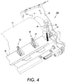
- FIG 3 shows perspective view of a media removal apparatus 300 viewed from the fuser nip exit and FIG. 4 shows a perspective view of a media removal apparatus 300 viewed from the nip exit side of the fuser illustrating the stripper fingers
- media removal apparatus 300 includes a fuser roll 12, stripper baffle 34, stripper finger structure 32, cam finger shaft 38, support arm 49, lower guide 50, track 54, a first cam 72, frame member 62, a camshaft 74, and a second cam 92.
- An imaging media sensor is positioned adjacent the media transport for sensing the position of imaging media.
- Firmware in CDA 110 processes signals generated by a media position sensor (not shown) for controlling operation of a finger stripper structure 300 forming a part of a media removal apparatus.
- baffle arm that is received in a first track forming a part of the track structures.
- the other end of the baffle arm is pivotally mounted on a shaft.
- the shaft also supports a boomerang shaped linkage adjacent one end thereof.
- the linkage is supported proximate its center by the stationary shaft.
- the other end of the linkage 88 acts as a cam follower that operatively engages cams carried by the camshaft.
- the cams 92 effect automatic movements of the stripping baffle structure between its home or standby position and an active position proximate the heated fuser roll for separating the portion of the imaging media beyond the lead edge portion separated by the strippers.
- the cams cause the cam follower ends of the linkage to rotate about the stationary shaft that, in turn, causes the shaft to move the arms attached to the baffle base member.
- the stripping baffle structure 34 comprises a castellated base member with openings through which the stripper finger assemblies pass during relative movement of the stripper finger and baffle structures.
- the function of the stripping baffle is to effect separation of the remainder of the imaging media after the lead edge thereof has been separated from the heated fuser roll by the stripper fingers.
- the stripper baffle is adapted to be moved from a home or standby position to continue separation of the imaging media once the stripper fingers have separated the lead edge of the imaging media.
- the shaft 38 pivotally supports a plurality of stripper finger assemblies 40. Each stripper finger assembly comprises a base member (not shown) fabricated from a suitable plastic or metal material.
- FIG. 5 is a block diagram of a system 500 for controlling an air knife in accordance with the present disclosure.
- System 500 comprises an input device 530 for receiving inputs from a user such as electro-photographic reproduction machine objectives and media characteristics, or data from optical sensors that indicate information as to the media being used for a particular job.
- Processor 510 may include at least one conventional processor or microprocessor that interprets and executes instructions.
- Storage 540 may be a random access memory (RAM) or another type of dynamic storage device that stores information and instructions for execution by processor 510.
- RAM random access memory
- Storage device 550 can include a one or more cache, read only memory (ROM), programmable ROM (PROM), erasable PROM (EPROM), electrically erasable PROM (EEPROM), flash, static RAM (SRAM), computer-readable medium having stored thereon a plurality of instructions, non-volatile memory (NVM), or other devices; however, the memory is not limited thereto.
- Storage device 450 can hold calibration data, a unique identifier for the electro-photographic reproduction machine and vision based input device, or a media access control address, and individualized software made by third parties for operating electro-photographic reproduction machine or fusing assembly.
- Software mean 550 may contain software objects 560 that when compiled by processor 510 determine the first angle ( ⁇ ), the second angle ( ⁇ ), the distance (d), and the pressure for the air knife.
- the software means 550 can also be used to perform leading edge acquisition and to generate a set of instructions to position air knife 250 at optimal position relative to the media and the fuse roll.
- Storage device in particular holds objects or modules for determining the optimized parameters given acquired setoff parameters from a user or from sensing devices. Once the software determines the optimized parameters, a control signal 50 is generated to position the air knife 250 at an optimal position for the job and the media being employed in the job.
- FIG. 6 is a flowchart of method 600 for controlling an air knife based on electro-photographic reproduction machine objective and media characteristics in accordance with the present disclosure.
- Method 600 begins by the acquisition of objectives 610 for the electro-photographic reproduction machine 100.
- objectives are one of body stripping, lead edge stripping, and user defined photographic reproduction machine objective.
- the media characteristics 620 are acquired for the particular objective being performed by the fusing subsystem.
- Example of media characteristics are coated media, uncoated media, physical dimension of the media, and weight of the media.
- action 630 optimization parameters are determined for the desired situation or job being performed by electro-photographic reproduction machine 100.
- action 630 a response value is calculated to determine the rotation, distance, or pressure to set air knife 250 where the response value would be maximized. Once the parameters have been determined control passes to action 640 for further processing.
- the optimized parameters are implemented to position the air knife 250 at the desired rotation, at the desired distance, and the desired pressure to operate the air knife at optimal performance.
- the rotation, distance, and pressure could be set manually by an operator or by the use of a controller such as CDA 110.
- FIG. 7 illustrates a flowchart of method 700 for controlling an air knife based on electro-photographic reproduction machine objective and leading edge acquisition.
- Method 700 begins by the acquisition of objectives 710 for the electro-photographic reproduction machine 100.
- objectives are one of body stripping, lead edge stripping, and user defined photographic reproduction machine objective.
- the media characteristics 720 are acquired for the particular objective being performed by the fusing subsystem.
- Example of media characteristics are coated media, uncoated media, physical dimension of the media, and weight of the media.
- method 700 acquires leading edge 730 data from an optical sensor such as a light emitting diode (LED) or laser, or a suitable input device.
- LED light emitting diode
- the optimization parameter are determined from the acquired objectives 710, acquired leading edge 730 data, and acquired media characteristics. Once the parameters have been determined control passes to action 750 for further processing.
- the air knife 250 is controlled based on the determined optimization parameters. With the acquisition of leading edge 730 the knife pressure can be shut off or reduced so the beam strength of the paper 230 could be used to assist in stripping the body of the sheet. Using the strength of the paper for stripping reduces power losses and potential gloss defects.
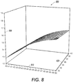
- FIG. 8 is a surface plot 800 of response value (830) of optimal parameter conditions for uncoated media in accordance with the present disclosure.
- the Graph shows the relationship of theta 810 ( ⁇ ) and phi ( ⁇ ) 820 for 60 gsm (grams per square metre) uncoated media for a given embodiment. The larger numbers are better for the response value shown in FIG. 8 .
- 60 gsm uncoated performs better with a large theta and is relatively insensitive to phi.
- the air knife 250 need not be rotated because phi ( ⁇ ) is not critical to achieving optimization.
- FIG. 9 is a surface plot 900 of response value (830) of optimal parameter conditions for coated media in accordance with the present disclosure.
- the Graphs shows the relationship of theta 810 ( ⁇ ) and phi ( ⁇ ) 820 for 90 gsm coated media.
- the coated optimal conditions are different.
- the larger numbers are better for the response value shown in FIG. 9 .
- the point of optimization occurs at the lower phi ( ⁇ ) 820 and lower theta ( ⁇ ) 810.
- both theta and phi should be changed to lower settings.
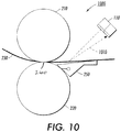
- FIG. 10 shows an enlarged end section schematic of the fusing assembly 1000 or media removal apparatus showing an air knife 250 in accordance with the present disclosure.
- fusing assembly 1000 includes a pressure roll 210, a fuse roll 220, and an air knife 250.
- fusing subsystem 200 includes a fuser roller 220 having a surface, and a pressure roller 210 that form a fusing nip 240 through which the sheet 230 is passed with an image on the copy sheet contacting fuser roller 220.
- the pressure roller 230 is loaded against the fuser roller 220 forming a fusing nip for providing the necessary pressure and dwell to fix an image to the copy sheet.
- the fusing assembly 1000 shows controller data acquisition 110 programmed to receive leading edge acquisition from an optical sensor so as to control air knife 250. It should be noted that CDA 110 could be programmed to receive other leading edge inputs to control air knife 250.
- Embodiments within the scope of the present invention may also include computer-readable media for carrying or having computer-executable instructions or data structures stored thereon.
- Such computer-readable media can be any available media that can be accessed by a general purpose or special purpose computer.
- Such computer-readable media can comprise RAM, ROM, EEPROM, CD-ROM or other optical disk storage, magnetic disk storage or other magnetic storage devices, or any other medium which can be used to carry or store desired program code means in the form of computer-executable instructions or data structures.
- a network or another communications connection either hardwired, wireless, or combination thereof
- any such connection is properly termed a computer-readable medium. Combinations of the above should also be included within the scope of the computer-readable media.
- Computer-executable instructions include, for example, instructions and data which cause a general purpose computer, special purpose computer, or special purpose processing device to perform a certain function or group of functions.
- Computer-executable instructions also include program modules that are executed by computers in stand-alone or network environments.
- program modules include routines, programs, objects, components, and data structures, etc. that perform particular tasks or implement particular abstract data types.
- Computer-executable instructions, associated data structures, and program modules represent examples of the program code means for executing steps of the methods disclosed herein. The particular sequence of such executable instructions or associated data structures represents examples of corresponding acts for implementing the functions described in such steps.
Landscapes
- Physics & Mathematics (AREA)
- General Physics & Mathematics (AREA)
- Engineering & Computer Science (AREA)
- Microelectronics & Electronic Packaging (AREA)
- Fixing For Electrophotography (AREA)
Claims (8)
- Verfahren zum Betreiben einer Druckvorrichtung mit einem Fixiersubsystem und einem Luftmesser, mit:Erfassen (610, 620) mindestens einer Aufgabe einer elektrofotografischen Reproduktionsvorrichtung und einer Medieneigenschaft;Ermitteln (630) von Optimierungsparameterwerten aus der mindestens einen Aufgabe einer elektrofotografischen Reproduktionsvorrichtung und der Medieneigenschaft;wobei das Fixiersubsystem eine Fixierwalze (220) und eine Druckwalze (310) aufweist, die jeweils um eine entsprechende Achse drehbar sind und die einen Spalt (240) bilden, den Medien durchlaufen;wobei das Luftmesser (250) eine Düse (255) hat, die einen Strom (260) aus Druckluft auf einen Auftreffpunkt (257) auf der Fixierwalze (220) lenkt, wobei das Luftmesser relativ zu der Fixierwalze (220) drehbar und verschiebbar ist;wobei der Auftreffpunkt (257) und die Düse (255) einen ersten Winkel (φ) bilden, wobei eine Linie von der Düse zu der Fixierwalze eine von zwei Tangenten bildet;wobei der Ausgang des Spalts (240) und der Auftreffpunkt (257) einem zweiten Winkel (θ) an dem Mittelpunkt der Drehung der Fixierwalze gegenüberliegen,dadurch gekennzeichnet, dassdie Optimierungsparameterwerte Werte für den ersten und den zweiten Winkel umfassen, und das Verfahren ferner umfasst:Steuern (640) des bereitgestellten Luftmessers (250) auf der Grundlage der Ermittlung der Optimierungsparameterwerte für den ersten und den zweiten Winkel;wobei die Aufgabe der fotografischen Reproduktionsvorrichtung eine Hauptteilablösung, eine Vorderkantenablösung oder eine benutzerdefinierte Aufgabe für die fotografische Reproduktionsvorrichtung ist;wobei die Medieneigenschaft beschichtete Medien, unbeschichtete Medien, eine physische Abmessung der Medien oder ein Gewicht der Medien betrifft;wobei ein Steuern des bereitgestellten Luftmessers (250) bewerkstelligt wird, indem der Abstand (d) von der Düse zu dem Auftreffpunkt (257) eingestellt und das Luftmesser relativ zu der Fixierwalze (220) in Drehung versetzt wird.
- Verfahren nach Anspruch 1, wobei die Optimierungsparameterwerte ferner Werte für den Druck für den Strom aus Druckluft und den Abstand (d) von der Düse (255) zu dem Auftreffpunkt (257) auf der Fixierwalze (220) umfassen.
- Verfahren nach einem der vorhergehenden Ansprüche, wobei das Verfahren ferner umfasst:
Empfangen von Daten bezüglich einer Vorderkante für Medien, die den Spalt durchlaufen, der durch die Fixierwalze und die Druckwalze gebildet ist; und Steuern des bereitgestellten Luftmessers (250) durch Einstellen des Stroms aus Druckluft, der die Düse des Luftmessers verlässt, in Reaktion darauf. - Druckvorrichtung, mit:einem Fixiersubsystem mit einer Fixierwalze (220) und einer Druckwalze (210), die jeweils um eine entsprechende Achse drehbar sind und einen Spalt (240) bilden, den Medien durchlaufen;einem Luftmesser (250) mit einer Düse (255) zum Lenken eines Stroms aus Druckluft auf einen Auftreffpunkt (257) auf der Fixierwalze (220), wobei das Luftmesser (250) relativ zu der Fixierwalze drehbar und verschiebbar ist;einem Prozessor (510) zur Ermittlung von Optimierungsparameterwerten aus mindestens einer Aufgabe einer elektrofotografischen Reproduktionsvorrichtung und aus einer Medieneigenschaft;wobei der Auftreffpunkt (257) und die Düse (255) einen ersten Winkel (φ) bilden, wobei eine Linie von der Düse zu der Fixierwalze (220) eine von zwei Tangenten bildet,wobei der Ausgang des Spalts (240) und der Auftreffpunkt (257) einem zweiten Winkel (θ) an dem Mittelpunkt der Drehung der Fixierwalze (220) gegenüberliegen;dadurch gekennzeichnet, dassder Prozessor (510) ausgebildet ist, Optimierungsparameterwerte für den ersten und den zweiten Winkel zu ermitteln, und eine Steuerung (150) vorgesehen ist, die ausgebildet ist, das Luftmesser auf der Grundlage der ermittelten Optimierungsparameterwerte zu steuern;wobei die Aufgabe für die fotografische Reproduktionsvorrichtung eine Hauptteilablösung, eine Vorderkantenablösung oder eine benutzerdefinierte Aufgabe für eine fotografische Reproduktionsvorrichtung ist; undwobei die Medieneigenschaft beschichtete Medien, unbeschichtete Medien, eine physische Abmessung der Medien oder ein Gewicht der Medien betrifft; undwobei die Steuerung (510) ausgebildet ist, das bereitgestellte Luftmesser zu steuern, indem der Abstand (d) von der Düse (255) zu dem Auftreffpunkt (257) eingestellt wird und das Luftmesser relativ zu der Fixierwalze (270) in Drehung versetzt wird.
- Druckvorrichtung nach Anspruch 4, wobei die Optimierungsparameterwerte Werte für den Druck für den Strom aus Druckluft und für einen Abstand (d) von der Düse zu dem Auftreffpunkt auf der Fixierwalze umfassen;
wobei das Ermitteln von Optimierungsparameterwerten durch Drehen des ersten Winkels und des zweiten Winkels bewerkstelligt wird;
wobei das Ermitteln der Optimierungsparameterwerte umfasst: Einstellen des Abstands von der Düse zu dem Auftreffpunkt. - Druckvorrichtung nach Anspruch 4 oder Anspruch 5, wobei die Vorrichtung ferner umfasst:
eine Sensoreinrichtung zur Erfassung einer Vorderkante der Medien, die durch den Spalt laufen, der durch die Fixierwalze und die Druckwalze gebildet ist. - Druckvorrichtung nach einem der Ansprüche 4 bis 6, wobei die Steuerung (510) ausgebildet ist, das vorgesehene Luftmesser (250) durch Einstellen des Stroms (260) aus Druckluft, der die Düse (251) des Luftmessers verlässt, zu steuern.
- Druckvorrichtung nach einem der Ansprüche 4 bis 6, wobei die Steuerung (510) ausgebildet ist, das bereitgestellte Luftmesser zu steuern, indem der Abstand (d) von der Düse (255) zu dem Auftreffpunkt (257) eingestellt und das Luftmesser relativ zu der Fixierwalze (270) in Drehung versetzt wird.
Applications Claiming Priority (1)
| Application Number | Priority Date | Filing Date | Title |
|---|---|---|---|
| US12/135,235 US7965969B2 (en) | 2008-06-09 | 2008-06-09 | Active rotation of air knife for increased performance |
Publications (2)
| Publication Number | Publication Date |
|---|---|
| EP2146254A1 EP2146254A1 (de) | 2010-01-20 |
| EP2146254B1 true EP2146254B1 (de) | 2019-09-11 |
Family
ID=41323393
Family Applications (1)
| Application Number | Title | Priority Date | Filing Date |
|---|---|---|---|
| EP09162211.8A Active EP2146254B1 (de) | 2008-06-09 | 2009-06-08 | Druckmaschine und Verfahren zum Betreiben einer Druckmaschine |
Country Status (3)
| Country | Link |
|---|---|
| US (1) | US7965969B2 (de) |
| EP (1) | EP2146254B1 (de) |
| JP (1) | JP2009294656A (de) |
Families Citing this family (10)
| Publication number | Priority date | Publication date | Assignee | Title |
|---|---|---|---|---|
| JP5455439B2 (ja) * | 2009-05-26 | 2014-03-26 | キヤノン株式会社 | 画像形成装置 |
| US8408270B2 (en) * | 2009-10-07 | 2013-04-02 | Xerox Corporation | Apparatuses useful in printing, fixing devices and methods of stripping substrates from surfaces in apparatuses useful in printing |
| JP5540768B2 (ja) * | 2010-02-26 | 2014-07-02 | 株式会社リコー | 画像形成装置 |
| JP5713272B2 (ja) * | 2010-03-15 | 2015-05-07 | 株式会社リコー | 定着装置及び画像形成装置 |
| JP5585486B2 (ja) * | 2011-02-17 | 2014-09-10 | コニカミノルタ株式会社 | 画像形成装置 |
| JP5323871B2 (ja) * | 2011-02-18 | 2013-10-23 | シャープ株式会社 | 画像形成装置 |
| JP5716506B2 (ja) * | 2011-04-11 | 2015-05-13 | コニカミノルタ株式会社 | 画像形成装置 |
| JP5712753B2 (ja) * | 2011-04-11 | 2015-05-07 | コニカミノルタ株式会社 | 画像形成装置 |
| JP5626255B2 (ja) * | 2012-04-10 | 2014-11-19 | コニカミノルタ株式会社 | 定着装置及び画像形成装置 |
| JP2015228043A (ja) * | 2015-09-16 | 2015-12-17 | 株式会社リコー | 定着装置、および画像形成装置 |
Citations (1)
| Publication number | Priority date | Publication date | Assignee | Title |
|---|---|---|---|---|
| US20080063441A1 (en) * | 2006-09-07 | 2008-03-13 | Xerox Corporation | Rotatable Air Knife |
Family Cites Families (13)
| Publication number | Priority date | Publication date | Assignee | Title |
|---|---|---|---|---|
| US5349199A (en) | 1993-04-29 | 1994-09-20 | Xerox Corporation | Sensing apparatus for reducing sheet detection and registration errors by using multiple light beam reflections |
| US5383014A (en) | 1993-05-20 | 1995-01-17 | Xerox Corporation | Photoreceptor belt motion sensor using linear position sensors |
| JP4402761B2 (ja) * | 1999-04-23 | 2010-01-20 | 東北リコー株式会社 | 印刷装置 |
| US20030039491A1 (en) | 2001-08-27 | 2003-02-27 | Bogoshian Gregory V. | Multi-function air knife |
| US20030049042A1 (en) | 2001-08-27 | 2003-03-13 | Xerox Corporation | Corrugating air knife |
| US6782228B1 (en) | 2003-01-30 | 2004-08-24 | Xerox Corporation | Intermittent stripper fingers and baffle for stripping copy media from a heated fuser roll |
| JP2005128333A (ja) * | 2003-10-24 | 2005-05-19 | Fuji Xerox Co Ltd | 画像形成装置 |
| US7259857B2 (en) | 2004-01-14 | 2007-08-21 | Xerox Corporation | Methods for automated uniformity assessment and modification of image non-uniformities |
| US7742732B2 (en) | 2005-12-09 | 2010-06-22 | Xerox Corporation | Fuser arranged for reduced pressure member speed, and an image forming device including the same |
| JP4714901B2 (ja) * | 2006-01-31 | 2011-07-06 | コニカミノルタビジネステクノロジーズ株式会社 | 定着装置および画像形成装置 |
| US20070206981A1 (en) | 2006-03-01 | 2007-09-06 | Xerox Corporation | Fusing apparatus including a sheet centering stripper assembly |
| US7545519B2 (en) | 2006-07-20 | 2009-06-09 | Xerox Corporation | Lead edge sheet curl sensor |
| US7505723B2 (en) | 2007-02-13 | 2009-03-17 | Xerox Corporation | Air knife system with pressure sensor |
-
2008
- 2008-06-09 US US12/135,235 patent/US7965969B2/en active Active
-
2009
- 2009-06-02 JP JP2009133202A patent/JP2009294656A/ja active Pending
- 2009-06-08 EP EP09162211.8A patent/EP2146254B1/de active Active
Patent Citations (1)
| Publication number | Priority date | Publication date | Assignee | Title |
|---|---|---|---|---|
| US20080063441A1 (en) * | 2006-09-07 | 2008-03-13 | Xerox Corporation | Rotatable Air Knife |
Also Published As
| Publication number | Publication date |
|---|---|
| US7965969B2 (en) | 2011-06-21 |
| JP2009294656A (ja) | 2009-12-17 |
| EP2146254A1 (de) | 2010-01-20 |
| US20090304419A1 (en) | 2009-12-10 |
Similar Documents
| Publication | Publication Date | Title |
|---|---|---|
| EP2146254B1 (de) | Druckmaschine und Verfahren zum Betreiben einer Druckmaschine | |
| US8903275B2 (en) | Fixing device and image forming apparatus incorporating same | |
| EP0905574B1 (de) | Feuchtigkeitskontrolle zur Beseitigung von Blattwellungen | |
| US9869953B2 (en) | Image forming apparatus | |
| US10078300B2 (en) | Fixing device and image forming apparatus | |
| US5987301A (en) | Paper conditioning system | |
| EP1293845B1 (de) | Zusammengesetzte Klinge als Unterstützung für das vollständige Übertragen eines Tonerbildes von einer lichtempfindlichen Oberfläche | |
| EP1288736A2 (de) | Multifunktionaler Luftmesser | |
| US5920751A (en) | Apparatus and method for controlling moisture and cooling rate for paper curl reduction | |
| US7831161B2 (en) | Method and apparatus for image forming of effectively detecting image data | |
| JP5448029B2 (ja) | 一様なグロス制御装置及び方法 | |
| US7751767B2 (en) | Rotatable air knife | |
| EP0929013B1 (de) | Führung zur Beseitigung von Wellen vor Schmelzfixiervorrichtung | |
| US7429995B2 (en) | Image forming apparatus | |
| US9703239B1 (en) | Fixing device having a guide member with a recessed shape | |
| CN107885059B (zh) | 图像形成装置 | |
| JP2008287069A (ja) | 帯電装置及び画像形成装置 | |
| EP1431840B1 (de) | Tonerbildübertragungsgerät | |
| US20070147911A1 (en) | Image forming apparatus | |
| US7787814B2 (en) | Edge wear reducing pressure roller and an electrostatographic reproduction machine having same | |
| JP2010032832A (ja) | 回転制御方法および画像形成装置 | |
| JP7472456B2 (ja) | 画像形成装置 | |
| JP6410623B2 (ja) | 現像装置、プロセスカートリッジおよび画像形成装置 | |
| JP3873969B2 (ja) | カラー画像形成装置 | |
| US6574450B2 (en) | Sheet pre-transfer device |
Legal Events
| Date | Code | Title | Description |
|---|---|---|---|
| PUAI | Public reference made under article 153(3) epc to a published international application that has entered the european phase |
Free format text: ORIGINAL CODE: 0009012 |
|
| AK | Designated contracting states |
Kind code of ref document: A1 Designated state(s): AT BE BG CH CY CZ DE DK EE ES FI FR GB GR HR HU IE IS IT LI LT LU LV MC MK MT NL NO PL PT RO SE SI SK TR |
|
| AX | Request for extension of the european patent |
Extension state: AL BA RS |
|
| 17P | Request for examination filed |
Effective date: 20100720 |
|
| 17Q | First examination report despatched |
Effective date: 20100813 |
|
| STAA | Information on the status of an ep patent application or granted ep patent |
Free format text: STATUS: EXAMINATION IS IN PROGRESS |
|
| GRAP | Despatch of communication of intention to grant a patent |
Free format text: ORIGINAL CODE: EPIDOSNIGR1 |
|
| STAA | Information on the status of an ep patent application or granted ep patent |
Free format text: STATUS: GRANT OF PATENT IS INTENDED |
|
| INTG | Intention to grant announced |
Effective date: 20190409 |
|
| GRAS | Grant fee paid |
Free format text: ORIGINAL CODE: EPIDOSNIGR3 |
|
| GRAA | (expected) grant |
Free format text: ORIGINAL CODE: 0009210 |
|
| STAA | Information on the status of an ep patent application or granted ep patent |
Free format text: STATUS: THE PATENT HAS BEEN GRANTED |
|
| AK | Designated contracting states |
Kind code of ref document: B1 Designated state(s): AT BE BG CH CY CZ DE DK EE ES FI FR GB GR HR HU IE IS IT LI LT LU LV MC MK MT NL NO PL PT RO SE SI SK TR |
|
| REG | Reference to a national code |
Ref country code: GB Ref legal event code: FG4D |
|
| REG | Reference to a national code |
Ref country code: CH Ref legal event code: EP |
|
| REG | Reference to a national code |
Ref country code: AT Ref legal event code: REF Ref document number: 1179236 Country of ref document: AT Kind code of ref document: T Effective date: 20190915 |
|
| REG | Reference to a national code |
Ref country code: DE Ref legal event code: R096 Ref document number: 602009059786 Country of ref document: DE |
|
| REG | Reference to a national code |
Ref country code: IE Ref legal event code: FG4D |
|
| REG | Reference to a national code |
Ref country code: NL Ref legal event code: MP Effective date: 20190911 |
|
| REG | Reference to a national code |
Ref country code: LT Ref legal event code: MG4D |
|
| PG25 | Lapsed in a contracting state [announced via postgrant information from national office to epo] |
Ref country code: LT Free format text: LAPSE BECAUSE OF FAILURE TO SUBMIT A TRANSLATION OF THE DESCRIPTION OR TO PAY THE FEE WITHIN THE PRESCRIBED TIME-LIMIT Effective date: 20190911 Ref country code: HR Free format text: LAPSE BECAUSE OF FAILURE TO SUBMIT A TRANSLATION OF THE DESCRIPTION OR TO PAY THE FEE WITHIN THE PRESCRIBED TIME-LIMIT Effective date: 20190911 Ref country code: NO Free format text: LAPSE BECAUSE OF FAILURE TO SUBMIT A TRANSLATION OF THE DESCRIPTION OR TO PAY THE FEE WITHIN THE PRESCRIBED TIME-LIMIT Effective date: 20191211 Ref country code: FI Free format text: LAPSE BECAUSE OF FAILURE TO SUBMIT A TRANSLATION OF THE DESCRIPTION OR TO PAY THE FEE WITHIN THE PRESCRIBED TIME-LIMIT Effective date: 20190911 Ref country code: SE Free format text: LAPSE BECAUSE OF FAILURE TO SUBMIT A TRANSLATION OF THE DESCRIPTION OR TO PAY THE FEE WITHIN THE PRESCRIBED TIME-LIMIT Effective date: 20190911 Ref country code: BG Free format text: LAPSE BECAUSE OF FAILURE TO SUBMIT A TRANSLATION OF THE DESCRIPTION OR TO PAY THE FEE WITHIN THE PRESCRIBED TIME-LIMIT Effective date: 20191211 |
|
| PG25 | Lapsed in a contracting state [announced via postgrant information from national office to epo] |
Ref country code: ES Free format text: LAPSE BECAUSE OF FAILURE TO SUBMIT A TRANSLATION OF THE DESCRIPTION OR TO PAY THE FEE WITHIN THE PRESCRIBED TIME-LIMIT Effective date: 20190911 Ref country code: LV Free format text: LAPSE BECAUSE OF FAILURE TO SUBMIT A TRANSLATION OF THE DESCRIPTION OR TO PAY THE FEE WITHIN THE PRESCRIBED TIME-LIMIT Effective date: 20190911 Ref country code: GR Free format text: LAPSE BECAUSE OF FAILURE TO SUBMIT A TRANSLATION OF THE DESCRIPTION OR TO PAY THE FEE WITHIN THE PRESCRIBED TIME-LIMIT Effective date: 20191212 |
|
| REG | Reference to a national code |
Ref country code: AT Ref legal event code: MK05 Ref document number: 1179236 Country of ref document: AT Kind code of ref document: T Effective date: 20190911 |
|
| PG25 | Lapsed in a contracting state [announced via postgrant information from national office to epo] |
Ref country code: AT Free format text: LAPSE BECAUSE OF FAILURE TO SUBMIT A TRANSLATION OF THE DESCRIPTION OR TO PAY THE FEE WITHIN THE PRESCRIBED TIME-LIMIT Effective date: 20190911 Ref country code: NL Free format text: LAPSE BECAUSE OF FAILURE TO SUBMIT A TRANSLATION OF THE DESCRIPTION OR TO PAY THE FEE WITHIN THE PRESCRIBED TIME-LIMIT Effective date: 20190911 Ref country code: PL Free format text: LAPSE BECAUSE OF FAILURE TO SUBMIT A TRANSLATION OF THE DESCRIPTION OR TO PAY THE FEE WITHIN THE PRESCRIBED TIME-LIMIT Effective date: 20190911 Ref country code: PT Free format text: LAPSE BECAUSE OF FAILURE TO SUBMIT A TRANSLATION OF THE DESCRIPTION OR TO PAY THE FEE WITHIN THE PRESCRIBED TIME-LIMIT Effective date: 20200113 Ref country code: RO Free format text: LAPSE BECAUSE OF FAILURE TO SUBMIT A TRANSLATION OF THE DESCRIPTION OR TO PAY THE FEE WITHIN THE PRESCRIBED TIME-LIMIT Effective date: 20190911 Ref country code: IT Free format text: LAPSE BECAUSE OF FAILURE TO SUBMIT A TRANSLATION OF THE DESCRIPTION OR TO PAY THE FEE WITHIN THE PRESCRIBED TIME-LIMIT Effective date: 20190911 Ref country code: EE Free format text: LAPSE BECAUSE OF FAILURE TO SUBMIT A TRANSLATION OF THE DESCRIPTION OR TO PAY THE FEE WITHIN THE PRESCRIBED TIME-LIMIT Effective date: 20190911 |
|
| PG25 | Lapsed in a contracting state [announced via postgrant information from national office to epo] |
Ref country code: IS Free format text: LAPSE BECAUSE OF FAILURE TO SUBMIT A TRANSLATION OF THE DESCRIPTION OR TO PAY THE FEE WITHIN THE PRESCRIBED TIME-LIMIT Effective date: 20200224 Ref country code: CZ Free format text: LAPSE BECAUSE OF FAILURE TO SUBMIT A TRANSLATION OF THE DESCRIPTION OR TO PAY THE FEE WITHIN THE PRESCRIBED TIME-LIMIT Effective date: 20190911 Ref country code: SK Free format text: LAPSE BECAUSE OF FAILURE TO SUBMIT A TRANSLATION OF THE DESCRIPTION OR TO PAY THE FEE WITHIN THE PRESCRIBED TIME-LIMIT Effective date: 20190911 |
|
| REG | Reference to a national code |
Ref country code: DE Ref legal event code: R097 Ref document number: 602009059786 Country of ref document: DE |
|
| PLBE | No opposition filed within time limit |
Free format text: ORIGINAL CODE: 0009261 |
|
| STAA | Information on the status of an ep patent application or granted ep patent |
Free format text: STATUS: NO OPPOSITION FILED WITHIN TIME LIMIT |
|
| PG2D | Information on lapse in contracting state deleted |
Ref country code: IS |
|
| PG25 | Lapsed in a contracting state [announced via postgrant information from national office to epo] |
Ref country code: DK Free format text: LAPSE BECAUSE OF FAILURE TO SUBMIT A TRANSLATION OF THE DESCRIPTION OR TO PAY THE FEE WITHIN THE PRESCRIBED TIME-LIMIT Effective date: 20190911 Ref country code: IS Free format text: LAPSE BECAUSE OF FAILURE TO SUBMIT A TRANSLATION OF THE DESCRIPTION OR TO PAY THE FEE WITHIN THE PRESCRIBED TIME-LIMIT Effective date: 20200112 |
|
| PGFP | Annual fee paid to national office [announced via postgrant information from national office to epo] |
Ref country code: FR Payment date: 20200520 Year of fee payment: 12 Ref country code: DE Payment date: 20200519 Year of fee payment: 12 |
|
| 26N | No opposition filed |
Effective date: 20200615 |
|
| PG25 | Lapsed in a contracting state [announced via postgrant information from national office to epo] |
Ref country code: SI Free format text: LAPSE BECAUSE OF FAILURE TO SUBMIT A TRANSLATION OF THE DESCRIPTION OR TO PAY THE FEE WITHIN THE PRESCRIBED TIME-LIMIT Effective date: 20190911 |
|
| PGFP | Annual fee paid to national office [announced via postgrant information from national office to epo] |
Ref country code: GB Payment date: 20200525 Year of fee payment: 12 |
|
| PG25 | Lapsed in a contracting state [announced via postgrant information from national office to epo] |
Ref country code: MC Free format text: LAPSE BECAUSE OF FAILURE TO SUBMIT A TRANSLATION OF THE DESCRIPTION OR TO PAY THE FEE WITHIN THE PRESCRIBED TIME-LIMIT Effective date: 20190911 |
|
| REG | Reference to a national code |
Ref country code: CH Ref legal event code: PL |
|
| PG25 | Lapsed in a contracting state [announced via postgrant information from national office to epo] |
Ref country code: LU Free format text: LAPSE BECAUSE OF NON-PAYMENT OF DUE FEES Effective date: 20200608 |
|
| REG | Reference to a national code |
Ref country code: BE Ref legal event code: MM Effective date: 20200630 |
|
| PG25 | Lapsed in a contracting state [announced via postgrant information from national office to epo] |
Ref country code: IE Free format text: LAPSE BECAUSE OF NON-PAYMENT OF DUE FEES Effective date: 20200608 Ref country code: LI Free format text: LAPSE BECAUSE OF NON-PAYMENT OF DUE FEES Effective date: 20200630 Ref country code: CH Free format text: LAPSE BECAUSE OF NON-PAYMENT OF DUE FEES Effective date: 20200630 |
|
| PG25 | Lapsed in a contracting state [announced via postgrant information from national office to epo] |
Ref country code: BE Free format text: LAPSE BECAUSE OF NON-PAYMENT OF DUE FEES Effective date: 20200630 |
|
| REG | Reference to a national code |
Ref country code: DE Ref legal event code: R119 Ref document number: 602009059786 Country of ref document: DE |
|
| GBPC | Gb: european patent ceased through non-payment of renewal fee |
Effective date: 20210608 |
|
| PG25 | Lapsed in a contracting state [announced via postgrant information from national office to epo] |
Ref country code: GB Free format text: LAPSE BECAUSE OF NON-PAYMENT OF DUE FEES Effective date: 20210608 Ref country code: DE Free format text: LAPSE BECAUSE OF NON-PAYMENT OF DUE FEES Effective date: 20220101 |
|
| PG25 | Lapsed in a contracting state [announced via postgrant information from national office to epo] |
Ref country code: TR Free format text: LAPSE BECAUSE OF FAILURE TO SUBMIT A TRANSLATION OF THE DESCRIPTION OR TO PAY THE FEE WITHIN THE PRESCRIBED TIME-LIMIT Effective date: 20190911 Ref country code: MT Free format text: LAPSE BECAUSE OF FAILURE TO SUBMIT A TRANSLATION OF THE DESCRIPTION OR TO PAY THE FEE WITHIN THE PRESCRIBED TIME-LIMIT Effective date: 20190911 Ref country code: FR Free format text: LAPSE BECAUSE OF NON-PAYMENT OF DUE FEES Effective date: 20210630 Ref country code: CY Free format text: LAPSE BECAUSE OF FAILURE TO SUBMIT A TRANSLATION OF THE DESCRIPTION OR TO PAY THE FEE WITHIN THE PRESCRIBED TIME-LIMIT Effective date: 20190911 |
|
| PG25 | Lapsed in a contracting state [announced via postgrant information from national office to epo] |
Ref country code: MK Free format text: LAPSE BECAUSE OF FAILURE TO SUBMIT A TRANSLATION OF THE DESCRIPTION OR TO PAY THE FEE WITHIN THE PRESCRIBED TIME-LIMIT Effective date: 20190911 |