EP2146255A1 - Recyclinghilfssystem, elektronische Vorrichtung und Recyclingshilfsverfahren - Google Patents
Recyclinghilfssystem, elektronische Vorrichtung und Recyclingshilfsverfahren Download PDFInfo
- Publication number
- EP2146255A1 EP2146255A1 EP20090165411 EP09165411A EP2146255A1 EP 2146255 A1 EP2146255 A1 EP 2146255A1 EP 20090165411 EP20090165411 EP 20090165411 EP 09165411 A EP09165411 A EP 09165411A EP 2146255 A1 EP2146255 A1 EP 2146255A1
- Authority
- EP
- European Patent Office
- Prior art keywords
- data
- electronic apparatus
- environment history
- traceability
- history data
- Prior art date
- Legal status (The legal status is an assumption and is not a legal conclusion. Google has not performed a legal analysis and makes no representation as to the accuracy of the status listed.)
- Ceased
Links
Images


Classifications
-
- G—PHYSICS
- G06—COMPUTING OR CALCULATING; COUNTING
- G06Q—INFORMATION AND COMMUNICATION TECHNOLOGY [ICT] SPECIALLY ADAPTED FOR ADMINISTRATIVE, COMMERCIAL, FINANCIAL, MANAGERIAL OR SUPERVISORY PURPOSES; SYSTEMS OR METHODS SPECIALLY ADAPTED FOR ADMINISTRATIVE, COMMERCIAL, FINANCIAL, MANAGERIAL OR SUPERVISORY PURPOSES, NOT OTHERWISE PROVIDED FOR
- G06Q10/00—Administration; Management
-
- G—PHYSICS
- G03—PHOTOGRAPHY; CINEMATOGRAPHY; ANALOGOUS TECHNIQUES USING WAVES OTHER THAN OPTICAL WAVES; ELECTROGRAPHY; HOLOGRAPHY
- G03G—ELECTROGRAPHY; ELECTROPHOTOGRAPHY; MAGNETOGRAPHY
- G03G15/00—Apparatus for electrographic processes using a charge pattern
- G03G15/06—Apparatus for electrographic processes using a charge pattern for developing
- G03G15/08—Apparatus for electrographic processes using a charge pattern for developing using a solid developer, e.g. powder developer
- G03G15/0894—Reconditioning of the developer unit, i.e. reusing or recycling parts of the unit, e.g. resealing of the unit before refilling with toner
-
- G—PHYSICS
- G03—PHOTOGRAPHY; CINEMATOGRAPHY; ANALOGOUS TECHNIQUES USING WAVES OTHER THAN OPTICAL WAVES; ELECTROGRAPHY; HOLOGRAPHY
- G03G—ELECTROGRAPHY; ELECTROPHOTOGRAPHY; MAGNETOGRAPHY
- G03G15/00—Apparatus for electrographic processes using a charge pattern
- G03G15/50—Machine control of apparatus for electrographic processes using a charge pattern, e.g. regulating differents parts of the machine, multimode copiers, microprocessor control
- G03G15/5075—Remote control machines, e.g. by a host
- G03G15/5079—Remote control machines, e.g. by a host for maintenance
-
- G—PHYSICS
- G03—PHOTOGRAPHY; CINEMATOGRAPHY; ANALOGOUS TECHNIQUES USING WAVES OTHER THAN OPTICAL WAVES; ELECTROGRAPHY; HOLOGRAPHY
- G03G—ELECTROGRAPHY; ELECTROPHOTOGRAPHY; MAGNETOGRAPHY
- G03G15/00—Apparatus for electrographic processes using a charge pattern
- G03G15/55—Self-diagnostics; Malfunction or lifetime display
- G03G15/553—Monitoring or warning means for exhaustion or lifetime end of consumables, e.g. indication of insufficient copy sheet quantity for a job
-
- G—PHYSICS
- G03—PHOTOGRAPHY; CINEMATOGRAPHY; ANALOGOUS TECHNIQUES USING WAVES OTHER THAN OPTICAL WAVES; ELECTROGRAPHY; HOLOGRAPHY
- G03G—ELECTROGRAPHY; ELECTROPHOTOGRAPHY; MAGNETOGRAPHY
- G03G21/00—Arrangements not provided for by groups G03G13/00 - G03G19/00, e.g. cleaning, elimination of residual charge
- G03G21/16—Mechanical means for facilitating the maintenance of the apparatus, e.g. modular arrangements
- G03G21/18—Mechanical means for facilitating the maintenance of the apparatus, e.g. modular arrangements using a processing cartridge, whereby the process cartridge comprises at least two image processing means in a single unit
- G03G21/1875—Mechanical means for facilitating the maintenance of the apparatus, e.g. modular arrangements using a processing cartridge, whereby the process cartridge comprises at least two image processing means in a single unit provided with identifying means or means for storing process- or use parameters, e.g. lifetime of the cartridge
- G03G21/1878—Electronically readable memory
- G03G21/1889—Electronically readable memory for auto-setting of process parameters, lifetime, usage
-
- G—PHYSICS
- G06—COMPUTING OR CALCULATING; COUNTING
- G06Q—INFORMATION AND COMMUNICATION TECHNOLOGY [ICT] SPECIALLY ADAPTED FOR ADMINISTRATIVE, COMMERCIAL, FINANCIAL, MANAGERIAL OR SUPERVISORY PURPOSES; SYSTEMS OR METHODS SPECIALLY ADAPTED FOR ADMINISTRATIVE, COMMERCIAL, FINANCIAL, MANAGERIAL OR SUPERVISORY PURPOSES, NOT OTHERWISE PROVIDED FOR
- G06Q10/00—Administration; Management
- G06Q10/08—Logistics, e.g. warehousing, loading or distribution; Inventory or stock management
- G06Q10/087—Inventory or stock management, e.g. order filling, procurement or balancing against orders
-
- G—PHYSICS
- G06—COMPUTING OR CALCULATING; COUNTING
- G06Q—INFORMATION AND COMMUNICATION TECHNOLOGY [ICT] SPECIALLY ADAPTED FOR ADMINISTRATIVE, COMMERCIAL, FINANCIAL, MANAGERIAL OR SUPERVISORY PURPOSES; SYSTEMS OR METHODS SPECIALLY ADAPTED FOR ADMINISTRATIVE, COMMERCIAL, FINANCIAL, MANAGERIAL OR SUPERVISORY PURPOSES, NOT OTHERWISE PROVIDED FOR
- G06Q10/00—Administration; Management
- G06Q10/30—Administration of product recycling or disposal
-
- G—PHYSICS
- G07—CHECKING-DEVICES
- G07C—TIME OR ATTENDANCE REGISTERS; REGISTERING OR INDICATING THE WORKING OF MACHINES; GENERATING RANDOM NUMBERS; VOTING OR LOTTERY APPARATUS; ARRANGEMENTS, SYSTEMS OR APPARATUS FOR CHECKING NOT PROVIDED FOR ELSEWHERE
- G07C3/00—Registering or indicating the condition or the working of machines or other apparatus, other than vehicles
- G07C3/08—Registering or indicating the production of the machine either with or without registering working or idle time
-
- G—PHYSICS
- G03—PHOTOGRAPHY; CINEMATOGRAPHY; ANALOGOUS TECHNIQUES USING WAVES OTHER THAN OPTICAL WAVES; ELECTROGRAPHY; HOLOGRAPHY
- G03G—ELECTROGRAPHY; ELECTROPHOTOGRAPHY; MAGNETOGRAPHY
- G03G15/00—Apparatus for electrographic processes using a charge pattern
- G03G15/55—Self-diagnostics; Malfunction or lifetime display
-
- G—PHYSICS
- G03—PHOTOGRAPHY; CINEMATOGRAPHY; ANALOGOUS TECHNIQUES USING WAVES OTHER THAN OPTICAL WAVES; ELECTROGRAPHY; HOLOGRAPHY
- G03G—ELECTROGRAPHY; ELECTROPHOTOGRAPHY; MAGNETOGRAPHY
- G03G2215/00—Apparatus for electrophotographic processes
- G03G2215/00987—Remanufacturing, i.e. reusing or recycling parts of the image forming apparatus
-
- G—PHYSICS
- G03—PHOTOGRAPHY; CINEMATOGRAPHY; ANALOGOUS TECHNIQUES USING WAVES OTHER THAN OPTICAL WAVES; ELECTROGRAPHY; HOLOGRAPHY
- G03G—ELECTROGRAPHY; ELECTROPHOTOGRAPHY; MAGNETOGRAPHY
- G03G2215/00—Apparatus for electrophotographic processes
- G03G2215/06—Developing structures, details
- G03G2215/066—Toner cartridge or other attachable and detachable container for supplying developer material to replace the used material
- G03G2215/0695—Toner cartridge or other attachable and detachable container for supplying developer material to replace the used material using identification means or means for storing process or use parameters
- G03G2215/0697—Toner cartridge or other attachable and detachable container for supplying developer material to replace the used material using identification means or means for storing process or use parameters being an electronically readable memory
-
- G—PHYSICS
- G03—PHOTOGRAPHY; CINEMATOGRAPHY; ANALOGOUS TECHNIQUES USING WAVES OTHER THAN OPTICAL WAVES; ELECTROGRAPHY; HOLOGRAPHY
- G03G—ELECTROGRAPHY; ELECTROPHOTOGRAPHY; MAGNETOGRAPHY
- G03G2221/00—Processes not provided for by group G03G2215/00, e.g. cleaning or residual charge elimination
- G03G2221/16—Mechanical means for facilitating the maintenance of the apparatus, e.g. modular arrangements and complete machine concepts
- G03G2221/18—Cartridge systems
- G03G2221/1823—Cartridges having electronically readable memory
-
- Y—GENERAL TAGGING OF NEW TECHNOLOGICAL DEVELOPMENTS; GENERAL TAGGING OF CROSS-SECTIONAL TECHNOLOGIES SPANNING OVER SEVERAL SECTIONS OF THE IPC; TECHNICAL SUBJECTS COVERED BY FORMER USPC CROSS-REFERENCE ART COLLECTIONS [XRACs] AND DIGESTS
- Y02—TECHNOLOGIES OR APPLICATIONS FOR MITIGATION OR ADAPTATION AGAINST CLIMATE CHANGE
- Y02W—CLIMATE CHANGE MITIGATION TECHNOLOGIES RELATED TO WASTEWATER TREATMENT OR WASTE MANAGEMENT
- Y02W90/00—Enabling technologies or technologies with a potential or indirect contribution to greenhouse gas [GHG] emissions mitigation
Definitions
- the present invention relates to a recycling aid system for aiding processes for recycling electronic apparatuses.
- Japanese Patent No. 3941354 discloses a system for determining a residual lifetime of a part mounted on an apparatus in order to mount the part on another apparatus appropriate for the determined residual lifetime.
- the criteria for determining the residual lifetime is a cumulative used time of the part mounted on the apparatus. That is, the residual lifetime is determined based on a value obtained by subtracting a use duration elapsed after the part was mounted on the apparatus from a value (lifetime) predetermined for the type of the part. Unused time of the apparatus is not taken into account for determining the residual lifetime.
- the lifetime of parts is a predetermined value relating to cumulative use time, and is predetermined for each type of the parts.
- the residual lifetime of a target part is not determined directly from the target part. Instead, physical measurement data is indirectly measured from a detection element that has characteristics equivalent to those of the target part. Then, the residual lifetime of the target part is determined based on correlation of characteristics between the target part and the detection element.
- the conventional technology (system for determining usage of apparatus mounted parts) includes the following features as necessary components.
- the conventional system includes the target part for which a residual lifetime is diagnosed, a detection element having characteristics equivalent to lifetime deterioration characteristics of the target part, and a synchronization unit for synchronizing power supply for the target part and power supply for the detection element, which are integrally mounted on the system.
- the conventional system includes a unit on a network storing the characteristics data, and a determination function for determining usage of the target part.
- a measurement apparatus for measuring lifetime deterioration characteristics of the target part beforehand is required, and an apparatus for measuring characteristics of the detection element at the time of shipment and at the time of diagnosis is required. In addition, man-hours for performing the measurements are necessary.
- the conventional technology has the following problems as a system for detecting residual lifetime of collected products or parts.
- the problems (1)-(6) of the conventional technology include many unrealistic elements from the viewpoint of the fact that optimum part selection is rapidly performed due to rapid technology advance in machine design in recent years and from the viewpoint of a decrease of recycling cost man-hours.
- the present invention is conceived in view of the above-mentioned problems, and the object of the present invention is to provide a recycling aid technique that can check a target apparatus in a state of a complete product without disassembling the apparatus, and that can use various data for performing recycling processes.
- an embodiment of the present invention can be configured as a recycling aid system including:
- a recycling aid technique can be provided that can check a target apparatus in a state of a complete product without disassembling the apparatus, and that can use various data for performing recycling processes.
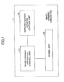
- Fig.1 shows an image forming apparatus 1 according to an embodiment of the electronic apparatus of the present invention.
- the image forming apparatus 1 includes an engine unit A3, an image forming apparatus control unit A1, and a wireless sensor network control unit A2.
- the engine unit A3 includes hardware engines such as a printer engine for performing an image forming process which is a main function of the image forming apparatus 1.
- ZigBee which is one of wireless standards and which uses IEEE 802.15.4 as the physical layer interface, is adopted for wireless communication in the wireless sensor network control unit A2.
- the best characteristics of ZigBee are low power consumption and low cost.
- the present embodiment adopts a configuration corresponding to a minimum basic system.
- physical measurement data detected in the body of the image forming apparatus 1 indicating a use environment, a transportation environment or a storage environment state are limited to temperature, humidity and vibration, and one part in the image forming apparatus 1 is measured for each of them.
- the image forming apparatus control unit A1 controls essential functions (printing, scanning, ... etc.) of the image forming apparatus 1.
- the wireless sensor network control unit A2 includes a function for periodically extracting environment history data and storing the data in a storage.
- the environment history data indicates use environment, transportation environment or storage environment state of the image forming apparatus 1, and the environment history data includes data of the temperature, humidity and vibration of a specific part in the inside of the image forming apparatus 1.
- the wireless sensor network control unit A2 includes a function for obtaining and storing traceability data of a route from initial shipment of the image forming apparatus 1 to a recycling factory. Further, the wireless sensor network control unit A2 includes a function for transmitting/receiving the data to/from a ZigBee relay node and a communication terminal and the like by radio.
- the image forming apparatus control unit A1 and the wireless sensor network control unit A2 are configured to communicate with each other via their USB interface circuits.
- each control unit is described in the following in more detail.
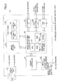
- Fig.2 shows a configuration of the image forming apparatus control unit A1 according to an embodiment of the present invention.
- the image forming apparatus control unit A1 is described with reference to Fig.2 .
- the image forming apparatus control unit A1 includes a power supply unit C1, an engine controller C2, an input/output unit C3 for each engine, an image reading unit C4, a front panel C5, an image processing controller unit C6, a network I/F C7, a PC/external I/F C8, and a USB I/F.
- the front panel C5 includes a key input unit E1 and a display unit E2.
- the image processing controller unit C6 includes a ROM D1, a RAM D2, a magnetic disc device D3, a NVRAM D4 and a CPU D5.
- the power supply unit C1 supplies power to each unit in the image forming apparatus control unit A1.
- the power supply unit C1 receives an AC current (alternating current) and outputs energy such as a DC current, a high voltage and the like necessary for operation of the image forming apparatus control unit A1.
- the engine controller C2 is provided for performing image forming processes that are the essential functions of the image forming apparatus 1.
- the engine controller C2 performs input control of various sensors via the engine input/output unit C3, and performs output control of a motor used for carrying print papers and a solenoid and the like.
- the image processing controller unit C6 controls image processing necessary for image formation.
- the image processing controller unit C6 receives image data from the image reading input unit C4, and receives a command or data from the general network interface C7, the PC/external interface C8 which is an interface supporting various standards for connecting to a PC or an external apparatus, or from the general USB interface C.
- the image processing controller unit C6 analyzes the image data, the command or data to perform image processing.
- the processed image data is sent to the engine controller C2 so that the image data is printed on a paper.
- the image processing controller unit C6 controls the key input unit E1 and the display unit E2 such as a LCD (Liquid Crystal Display) on the front panel C5 that is an interface with a human.
- Programs corresponding to a series of procedures are stored in the ROM D1 in the image processing controller unit C6. Processes are sequentially performed by the CPU D5 based on the programs while temporarily storing data used for the processes in the RAM D2.
- the NVRAM (Non-Volatile Random Access Memory) D4 and the magnetic disc apparatus D3 store data which needs to be stored even in a state in which the power supply unit C1 is off.
- a flash ROM and the like can be used as the ROM D1 such that a stored program can be updated into a newest program via the network interface C7 based on an instruction from a product maintenance management server (described later) that manages maintenance and management data of the image forming apparatuses collectively.
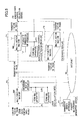
- Fis.3 shows a configuration of the wireless sensor network control unit A2.
- the wireless sensor network control unit A2 is described with reference to Fig.3 .
- the wireless sensor network control unit A2 includes an antenna B1, a matching circuit B2, an RF transmit and receive circuit B3, a temperature sensor B4, a humidity sensor B5, and a vibration sensor B6, an MPU B7, a USB I/F B8, an NVRAM B9, a RAM B10, a ROM B11, a secondary battery B12, and a power source selector/charge circuit B13.
- the wireless sensor network control unit A2 When an AC is input to the image forming apparatus control unit A1 so that the power supply unit C1 is ON and a DC is supplied, the wireless sensor network control unit A2 receives a DC input from the USB interface C9 by using bus power, and can operate using the power.
- the wireless sensor network control unit A2 When a DC is not supplied from the image forming apparatus control unit A1, the wireless sensor network control unit A2 operates by obtaining energy from the secondary battery B12. In addition, the secondary battery B12 is charged as necessary when DC is provided from the image forming apparatus control unit A1.
- the power selector / charge circuit unit B13 performs the power selection control and the automatic charge control.
- the MPU (Micro Processing Unit) B7 controls the whole of the wireless sensor network control unit A2.
- the temperature sensor B4, the humidity sensor B5 and the vibration sensor B6 obtain the environment history data of temperature, humidity and vibration at each specific part in the image forming apparatus 1.
- the MPU B7 receives the environment history data. Then, the environment history data is temporarily stored in the RAM B10, and is stored in the NVRAM B9 as necessary.
- the traceability data of the route that is input as an electronic wave from the antenna B1 is effectively extracted by the matching circuit B2.
- the traceability data is input to the MPU B7 via the RF (Radio Frequency) transmit and receive circuit B3. After that, the data is temporarily stored in the RAM B10, and stored in the NVRAM B9 as necessary.
- the traceability data may be identification information of a communication apparatus (ZigBee/IP conversion GW apparatus, broadband router, and the like) which is connected to the wireless sensor network control unit A2.
- the data (environment history data and traceability data) stored in the RAM B10 or the NVRAM B9 are transferred to a management server apparatus via the antenna B1 and the like each time when the image forming apparatus 1 arrives at a data send and receive terminal provided in each location point (factory, warehouse, sales side, etc.), or each time when it becomes possible that the image forming apparatus 1 can perform communication with a ZigBee node (described later) in each location.
- the data is deleted from the memory so that new data can be stored in an available area of the RAM B10 or the NVRAM B9 in the wireless sensor network control unit A2.
- Programs corresponding to the control procedures are stored in the ROM B11 of the wireless sensor network control unit A2 so that processes are executed sequentially.
- a flash ROM and the like can be used as the ROM B11 such that the program can be updated into a newest program via the network interface C7 and the USB interfaces C9 and B8 based on an instruction from the management server apparatus.
- a multifunction machine is used as a concrete example of the image forming apparatus 1.
- the following example shows a route from the time when the multifunction machine is shipped as a new product until the multifunction machine is transported to a recycling center after the whole use period of the multifunction machine ends.
- the route to be traced there are seven locations on the route to be traced, which are a new product manufacturing factory P1, a sales company warehouse P2, a user (installation site) P3, a manufacturer control collection warehouse P4, a manufacturer control collection center P5, a manufacturer control recycling center P6 and an exchange center P8.
- the exchange center P8 is a joint collection location which is not controlled by a single manufacture, and the exchange center P8 collects machines of various manufacturers.
- the recycling aid system of the present embodiment includes the multifunction machine that is provided with the image forming apparatus control unit A1 and the wireless sensor network control unit A2, a communication apparatus (such as after mentioned ZigBee/IP conversion GW apparatus), and the management server apparatus.
- a new product (multifunction machine) NM including the before-mentioned image forming apparatus control unit A1 and the wireless sensor network control unit A2 is manufactured.
- the new product manufacturing factory P1 is provided with a ZigBee/IP conversion gateway 1a as a component of the recycling aid system.
- the multifunction machine NM can perform radio communication with the ZigBee/IP conversion gateway 1a. Also, based on the function of the ZigBee/IP conversion gateway 1a, the multifunction machine NM can communicate with terminal apparatuses 1b connected to a LAN (Local Area Network) in the factory.
- LAN Local Area Network
- the ZigBee/IP conversion gateway 1a and the LAN terminal 1b can also connect to the Internet IW. Therefore, the multifunction machine NM can perform data communication with the management server apparatus 7a in the product maintenance management center P7.
- the multifunction machine NM sends initial values to the management server apparatus 7a, so that the management server apparatus 7a stores the initial values.
- the initial values are a machine number of the multifunction machine, date and time of finishing, total number of print pages, a setting value of environment history data extraction store period, and a setting value of environment history data sampling cycle.
- the management server apparatus 7a stores identification information of the multifunction machine NM. The identification information may be included in the initial values. After sending the initial values, measurement of traceability data and environment history data can start.
- Identification information of the ZigBee/IP conversion gateway 1a in the factory (and in other locations) is also registered in the management server apparatus 7a.
- data is transmitted to the management server apparatus 7a from the multifunction machine NM via the ZigBee/IP conversion gateway 1a, both of the identification information of the multifunction machine 1 and the identification of the ZigBee/IP conversion gateway 1a are sent to the management server apparatus 7a with the data.
- the management server apparatus 7a can detect the passing point (gateway) of the multifunction machine NM by detecting the identification information included in received data.
- the wireless sensor network control unit A2 obtains traceability data from a communication apparatus (ZigBee/IP conversion gateway), and transmits the traceability data to the management server apparatus 7a.
- a communication apparatus ZigBee/IP conversion gateway
- the above-mentioned identification information of the multifunction machine and the communication apparatus sent from the communication apparatus may be used as the traceability data.
- a truck carrying the multifunction machine NM leaves the factory, and arrives at the sales company warehouse P2. Even in the transportation stage, measurement of the environment history data is continuing.
- a ZigBee/IP conversion gateway 2a is also installed in the sales company warehouse P2.
- the management server apparatus 7a in the product maintenance management center P7 stores data that can specify the passing location (P2) of the multifunction machine NM.
- traceability data and environment history data stored in a memory in the wireless sensor network control unit A2 is transferred to the management server apparatus 7a via the ZigBee/IP conversion gateway 2a.
- the multifunction machine NM for which a user and an installation site are determined leaves the sales company warehouse P2 and arrives at the user site (installation site) P3 as shown in Fig.5 .
- the ZigBee/IP conversion gateway does not exist in the installation site of the user.
- the installation site is provided with a LAN connected to the Internet IW via a broadband router 3a.
- the multifunction machine NM can connect to the Internet IW via the broadband router 3a of the user, so that the multifunction machine NM can communicate with the product maintenance management center P7.
- the management server apparatus 7a receives and stores traceability data and environment history data that are obtained by the multifunction machine NM.
- the environment history data is transferred to the management server apparatus 7a via the network interface of the multifunction machine NM one after another at a predetermined cycle.
- the multifunction machine NM is collected by the manufacturer as a collected machine, and the multifunction machine NM arrives at a collection warehouse P4 managed by the manufacture. Meanwhile, measurement of the environment history data is continuing in the multifunction machine NM. As shown in Fig.5 , like other locations except for the user site, a ZigBee/IP conversion gateway 4a is provided in the manufacturer control collection warehouse P4.
- the multifunction machine NM sends traceability data and environment history data to the management server apparatus 7a in the product maintenance management center P7, so that the management server apparatus 7a can store the data, and can know the arrival of the multifunction machine NM at the location P4.
- the above-mentioned management control is similarly repeated from the time when the multifunction machine NM leaves the manufacturer control collection warehouse P4 until it enters the manufacturer control recycling center P6 via the manufacturer control collection center P5 as shown in Fig.6 .
- the multifunction machine NM continues to obtain and store environment history data, and the multifunction machine NM transfers traceability data and sends environment history data to the management server apparatus 7a at each location.
- the apparatus specific management data includes traceability data and environment history data that are collected by the management server apparatus 7a.
- conditions required for recycling the collected multifunction machine NM as a complete machine are input from the front panel of the multifunction machine NM, and the input information is transmitted to the management server apparatus 7a in the product maintenance management center P7.
- the input information is compared with stored data in the management server apparatus 7a.
- the comparison result (which may include traceability data and environment history data) is displayed on a display part of the front panel or is printed by the multifunction machine NM via the Internet IW and the ZigBee/IP conversion gateway 6a, so that the recycling process worker can know the comparison result instantaneously.
- the worker checks the result and the actual state of the multifunction machine NM in order to finally determine parts that need to be replaced and/or parts that need to be adjusted for the multifunction machine NM.
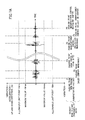
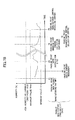
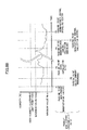
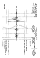
- Figs.7A-9C show output examples of traceability data (moving history) and environment history data of a multifunction machine obtained by the recycling aid system of the present embodiment.
- Figs.7A-9C show the simplest examples in which environment history data used for determining whether the collected multifunction machine can be recycled is limited to parameters of vibration (up and down direction), humidity, and temperature. As shown in the figure, an allowable limit point is provided for each parameter, and a maximum value and a minimum value are shown for each parameter.
- an output format is set such that data is output as a graph and representative values are shown as a maximum value (max) and a minimum value (min).
- the output examples 1 in Figs.7A-7C show that the subject multifunction machine has history data less than the allowable limit point in each of vibration, humidity and temperature.
- the traceability data of the multifunction machine indicates that the subject multifunction machine has passed through a regular product moving route (product manufacturing factory P1 --> sales company warehouse P2 --> user installation site P3 --> manufacturer control collection warehouse P4 --> manufacturer control collection center P5 --> manufacturer control recycling center P6). Since the environment history data and the traceability data do not indicate any abnormal value, the collected multifunction machine is determined to be a good collected multifunction machine, so that the machine is recycled by performing minimum tune-up in consideration of elements of other apparatus specific data.
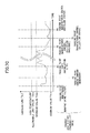
- Figs.8A-8C show an example in which the subject collected multifunction machine has passed through the regular route, but, environment history data exceeds the allowable limit point in vibration and temperature.
- the management server apparatus 7a compares the environment history data with parts specification data stored in the server apparatus 7a as apparatus specific data. Then, the management server apparatus 7a transmits replacement candidates of parts which may have problem in relation to the unallowable vibration and temperature, and/or transmits an adjusting method for the parts to the display part of the multifunction machine placed in the recycling site or to a personal computer connected to the LAN in the recycling site via the Internet and the ZigBee/IP conversion gateway.
- the transmitted data is displayed on the display part or on the computer as a list.
- part replacement and adjustment are performed efficiently based on the displayed list so that a complete machine is reproduced from the collected multifunction machine.
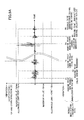
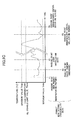
- Figs.9A-9C show an example indicating that the subject multifunction machine has not passed through the regular route, and the environment history data exceeds the allowable limit point in all of vibration, humidity and temperature.
- the traceability data does not include passing history data at the manufacturer control collection warehouse P4
- the collected multifunction machine since the environment history data far exceeds the allowable limit point in every parameter, it can be determined that the collected multifunction machine has passed hostile environments. In such a case, it is determined that the machine cannot be recycled as a complete machine based on a comprehensive recycling availability determination in the product maintenance management center P7.
- the collected multifunction machine is used for resource recycling in other routes, that is, parts and/or units of the collected multifunction machine are recycled, for example.
- Fig.10 shows a flowchart of an embodiment of the environment history data storing process.
- processes for initial setting are performed in the new product manufacturing factory P1.
- Other processes are performed in each place.
- the wireless sensor network control unit A2 of the multifunction machine starts self-diagnosis in step S11. More particularly, before starting processes after that, the wireless sensor network control unit A2 executes a diagnosis routine for checking whether functions in the wireless sensor network control unit A2 work normally.
- step S12 the error cause and log information at the time are displayed on the front panel C5 of the multifunction machine. The process cannot proceed further until the abnormality is recovered.
- step S14 initial setting such as register setting is performed for the MPU B7 of the wireless sensor network control unit A2 and for mode selection of peripheral control, and the like.
- Initial setting for the image forming apparatus control unit A1 has already been performed in the manufacturing process before starting this process routine.
- the process goes to step S15, so that the wireless sensor network control unit A2 enters in a state of waiting for inputs of the environment history data extraction/store period.
- the extraction/store period is a value determined beforehand based on parameters such as a product assurance period of the multifunction machine as a new product, a product assurance period of a recycled multifunction machine, and specification of the memory in the wireless sensor network control unit A2, and the like.
- step S16 When this value is normally input as the extraction/store period, the process goes to step S16.
- the wireless sensor network control unit A2 enters a state of waiting for inputs of an environment history data sampling cycle.
- step S17 When a value determined based on parameters such as the product assurance period and the specification of the wireless sensor network control unit A2 is normally input, the process goes to step S17.
- the step S17 is a state in which every preprocessing step necessary for execution of the wireless sensor network control unit A2 has been completed. From this step, physical measurement data are obtained by each sensor, and stored into the memory via the MPU B7 at the environment history data sampling cycle.
- step S19 when the multifunction machine NM as a new product leaves the new product manufacturing factory P1 and arrives at the sales company warehouse P2, the multifunction machine NW becomes able to communicate with the ZigBee/IP conversion gateway 2a.
- the process goes to step S19, so that environment history data and traceability data stored so far are transferred to the management server apparatus 7a.
- a replacement part candidate list output process is described as an example process in recycling processes.
- the multifunction machine collected machine
- the manufacturer control recycling center P6 via the regular passing points from the sales company warehouse P2
- recycling processes for recycling the collected multifunction machine into a complete machine start For performing recycling processes efficiently, it is necessary to determine whether recycling is available, and to determine parts to be replaced and parts to be adjusted.
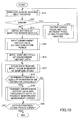
- Fig.11 shows a flowchart of the replacement part candidate list output process of the present embodiment.
- the worker of the recycling process instructs the multifunction machine to enter a recycling mode from the front panel of the multifunction machine so that the multifunction machine performs self-diagnosis in step S21,
- collected multifunction machines are largely varied in quality.
- the multifunction machine performs self-diagnoses for all functions including the basic function and the wireless sensor network function in step S21.
- step S23 the multifunction machine displays the error cause and log information at that time on the display part of the front panel C5 in step S22. In this step, if a serious error relating to the basic function is detected, it is determined that the multifunction machine cannot be recycled.
- step S24 initial setting for the system is performed.
- the setting information may indicate a client and the like from which conditions are input, and indicates a peripheral apparatus and the like from which the result is output.
- step S25 a network communication is established between the multifunction machine and the management server apparatus 7a in the product maintenance management center P7.
- the management server apparatus 7a determines whether update of a control program in the multifunction machine is necessary in step 27. If it is determined that the update is necessary, the control program is updated from the management server apparatus 7a in step S26. When it is determined that the update is unnecessary, the multifunction machine enters a state of waiting for recycling condition input.
- the user inputs three items as the conditions for determining availability of recycling of the multifunction machine.
- the three items are an allowable limit value of the environment history temperature, an allowable limit value of the environment history humidity, and an allowable limit value of environment history vibration.
- the system determines that the input values are proper values, the values are sent to the management server apparatus 7a.
- the management server apparatus 7a compares the conditions with every machine specific history data that has been stored in the management server apparatus 7a in step S29, so that it is determined whether the multifunction machine can be recycled as a complete machine in step S30.
- the multifunction machine is not recycled as a complete machine, but is carried to other processes for utilizing the multifunction machine as resource recycling or parts/units recycling in step S31.
- the product maintenance management center P7 may manage apparatus specific management data including additional data which is not described in the above embodiment.
- the apparatus specific management data may include a total elapsed-time from shipment of new product until delivery to the recycling factory, a total elapsed time of power-on, a total number of times of producing images, maintenance history of the multifunction machines in the market, and history of part replacement due to design change, and the like.
- the determination of availability of recycling and replacement /adjustment items are determined based on such apparatus specific management data.
- the recycling aid system of the present invention includes unlimited possibilities for improving efficiency in recycling processes.
- Fig.12A shows examples of recycling condition inputs that may be used
- Fig.12B shows examples of information to be compared with the condition items.
- the system of the present embodiment is provided with a function for periodically extracting and storing environment history data such as temperature, humidity and vibration at a specific part in the image forming apparatus (electronic apparatus) during the whole period, including any unused period, from the time when the electronic apparatus is shipped as a new product to the time when the electronic apparatus is collected due to expiration of the product lifetime and is recycled in the factory, in which the environment history data indicates use environment, transportation environment or storage environment state of the electronic apparatus.
- the system is provided with a function for storing traceability data of the route from the shipment to the recycling factory.
- Multifaceted data including not only accumulated use time data but also unused time and route history until collection can be used for determining recycling of the electronic apparatus (including diagnosis of residual lifetime and diagnosis of failure).
- an accurate diagnosis can be carried out based on actual circumstances.
- the quality of recycled electronic apparatuses can be improved, and the number of recycled electronic apparatuses introduced on the market can increase.
- the technique of the present invention can contribute to resources recycling and environment preservation.
- the electronic apparatus by inputting necessary conditions for recycling the electronic apparatus from the operation panel of the electronic apparatus, based on the whole history data from shipment of the electronic apparatus until the electronic apparatus is returned to the recycling factory, the electronic apparatus can output availability determination data indicating whether the electronic apparatus or the inside unit or the like can be recycled and information on necessary conditions to the display part or to a printing mechanism.
- the whole data of the electronic apparatus including not only the environment history data and the traceability data but also specific data stored in the management server can be used for residual lifetime diagnosis or failure diagnosis. Accordingly, an accurate diagnosis may be carried out comprehensively according to actual situations from various perspectives.
- system of the present embodiment includes a function for easily outputting, at the recycling factory, recycling availability determination results, recycling process instruction lists, replacement parts candidate lists and the like, an efficiency in process flow in the recycling stage (including residual life time diagnosis or failure diagnosis) can be improved.
- the technique of the present embodiment it is not necessary to disassemble the electronic apparatus for diagnosis. Since special tools or measurement devices or the like are not necessary for carrying out a diagnosis, diagnosis time can be reduced. Accordingly, the cost for recycling can be reduced. In addition, the time required for feedback to design can be reduced by effectively using data in the product maintenance management server, and the quality of the electronic apparatus can be improved.
- the technique of the present invention contributes to increase of the number of the recycled electronic apparatuses on the market. As a result, the technique contributes to resource recycling and environment preservation.
- the wireless sensor network module (control unit) necessary for storing and communication of the environment history data is provided separately from each module of the main functions which are necessary for the main purpose of the electronic apparatus.
- the wireless sensor network module is configured to be able to easily connect to the controller of the electronic apparatus via a general I/F.
- the wireless senor network module can be used for general purposes irrespective of the specification of the main function or the model of the electronic apparatus.
- the module can be realized at low cost, and the module that has been used can be recycled for another model.
- the technique of the present invention contributes to effective use of resources and environment preservation.
- the recycling aid system of the present embodiment is a successive data storage type system. More particularly, in the recycling aid system, a data transmit and receive terminal or a relay node is provided at each passing point for obtaining traceability data of the electronic apparatus. Each time when the electronic apparatus arrives at a passing point, the electronic apparatus sends, to the product maintenance management server, the environment history data and the route traceability data stored in the wireless sensor network module so far via the data transmit and receive terminal or the relay node. After sending the data, new data can be stored in the area that becomes available in the storage device in the wireless sensor network module. Accordingly, storage capacity of the storing device in the wireless sensor network module can be configured to be as small as possible.
- this feature has the effects of reducing cost for operating the system, and of reducing a failure ratio of the apparatus.
- the history data and the like can be stored safely, quickly and efficiently. As a result, accurate and quick recycling (including residual lifetime diagnosis or failure diagnosis) becomes possible.
- the wireless sensor network module includes a primary battery or a secondary battery for supplying power in a period when the electronic apparatus is not used.
- the wireless sensor network module includes a power source selection control function which enables the module to receive power from the AC input power source circuit in the electronic apparatus when the electronic apparatus is used.
- consumption of the battery in the wireless sensor network module can be kept small. As a result, a system which is stable for a long time can be provided.
- the wireless sensor network module includes a function for automatically switching between charge and discharge of a secondary battery, which function can charge a secondary battery in the wireless sensor network module by the energy obtained from the AC input power source.
- This function has the effect of operating the system stably for as long a time as possible.
- consumption of a battery as a part can be largely reduced.
- control programs of the electronic apparatus and the wireless sensor network module can be updated via the network interface in the electronic apparatus.
- This function has the effects that malfunction of the program can be quickly fixed, and that program changes due to technical advances can be quickly supported. Thus, this function contributes to preventing program malfunction and to improving work efficiency of users.
- the system can be easily used without replacement of hardware for various electronic apparatuses which are different from each other in model or specification. Since the setting can be carried out without any special apparatus, this technique contributes to reducing total cost for manufacturing and using the electronic apparatus. In addition, it becomes possible to store proper environment history data according to the specification of the electronic apparatus for a long time. Thus, the technique can contribute to performing an accurate diagnosis.
- the environment history data sampling cycle can be arbitrarily set via the operation panel or the network interface of the electronic apparatus, various system use methods which are different from each other due to models and specifications of the electronic apparatus can be flexibly supported. Accordingly, the environment history data can be collected under optimal condition, so that analysis for the data can be performed effectively and accurately.
- the technique of the present invention contributes to the improvement of reliability of the product from shipment to recycling.
- the electronic apparatus can be provided with an operation security function such that each operation such as display instruction and print output instruction for the history data cannot be executed by unspecified users.
- the electronic apparatus can be used only by inputting a machine number of the electronic apparatus, operator ID, and a password, for example. Accordingly, an occurrence of trouble of the electronic apparatus due to erroneous operation can be prevented, and a malfunction of the system due to use by a third person can be prevented. In addition, leakage of secret information of the manufacturer and leakage of personal information can be prevented. As a result, a reliable and accurate diagnosis becomes possible by the system of the present invention.
Landscapes
- Business, Economics & Management (AREA)
- Physics & Mathematics (AREA)
- General Physics & Mathematics (AREA)
- Engineering & Computer Science (AREA)
- Economics (AREA)
- Human Resources & Organizations (AREA)
- Strategic Management (AREA)
- Quality & Reliability (AREA)
- Theoretical Computer Science (AREA)
- General Business, Economics & Management (AREA)
- Entrepreneurship & Innovation (AREA)
- Tourism & Hospitality (AREA)
- Marketing (AREA)
- Operations Research (AREA)
- Life Sciences & Earth Sciences (AREA)
- Sustainable Development (AREA)
- Development Economics (AREA)
- Accounting & Taxation (AREA)
- Finance (AREA)
- Computer Vision & Pattern Recognition (AREA)
- Microelectronics & Electronic Packaging (AREA)
- Control Or Security For Electrophotography (AREA)
- Management, Administration, Business Operations System, And Electronic Commerce (AREA)
Priority Applications (1)
| Application Number | Priority Date | Filing Date | Title |
|---|---|---|---|
| EP17150019.2A EP3196707A1 (de) | 2008-07-18 | 2009-07-14 | Recyclingunterstützungssystem, elektronische vorrichtung und recyclingunterstützungsverfahren |
Applications Claiming Priority (1)
| Application Number | Priority Date | Filing Date | Title |
|---|---|---|---|
| JP2008186798A JP5200725B2 (ja) | 2008-07-18 | 2008-07-18 | 電子機器の再生支援システム |
Related Child Applications (1)
| Application Number | Title | Priority Date | Filing Date |
|---|---|---|---|
| EP17150019.2A Division EP3196707A1 (de) | 2008-07-18 | 2009-07-14 | Recyclingunterstützungssystem, elektronische vorrichtung und recyclingunterstützungsverfahren |
Publications (1)
| Publication Number | Publication Date |
|---|---|
| EP2146255A1 true EP2146255A1 (de) | 2010-01-20 |
Family
ID=41077694
Family Applications (2)
| Application Number | Title | Priority Date | Filing Date |
|---|---|---|---|
| EP20090165411 Ceased EP2146255A1 (de) | 2008-07-18 | 2009-07-14 | Recyclinghilfssystem, elektronische Vorrichtung und Recyclingshilfsverfahren |
| EP17150019.2A Withdrawn EP3196707A1 (de) | 2008-07-18 | 2009-07-14 | Recyclingunterstützungssystem, elektronische vorrichtung und recyclingunterstützungsverfahren |
Family Applications After (1)
| Application Number | Title | Priority Date | Filing Date |
|---|---|---|---|
| EP17150019.2A Withdrawn EP3196707A1 (de) | 2008-07-18 | 2009-07-14 | Recyclingunterstützungssystem, elektronische vorrichtung und recyclingunterstützungsverfahren |
Country Status (3)
| Country | Link |
|---|---|
| US (1) | US20100017240A1 (de) |
| EP (2) | EP2146255A1 (de) |
| JP (1) | JP5200725B2 (de) |
Cited By (1)
| Publication number | Priority date | Publication date | Assignee | Title |
|---|---|---|---|---|
| EP3608538A1 (de) * | 2018-12-18 | 2020-02-12 | Vestas Wind Systems A/S | Modellbasierte aufrüstungslösungen für windturbinen |
Families Citing this family (3)
| Publication number | Priority date | Publication date | Assignee | Title |
|---|---|---|---|---|
| EP3783866A1 (de) | 2014-06-11 | 2021-02-24 | Convida Wireless, LLC | Abbildungsdienst zur weiterleitung von lokalem inhalt |
| KR102137598B1 (ko) * | 2014-06-30 | 2020-07-24 | 콘비다 와이어리스, 엘엘씨 | 과거 이력 데이터에 기초하는 네트워크 노드 가용성 예측 |
| JP2019057092A (ja) * | 2017-09-20 | 2019-04-11 | 富士ゼロックス株式会社 | 情報処理装置及びプログラム |
Citations (13)
| Publication number | Priority date | Publication date | Assignee | Title |
|---|---|---|---|---|
| EP1191485A1 (de) | 2000-09-20 | 2002-03-27 | Kobelco Construction Machinery Co., Ltd. | Verfahren und Vorrichtung zur Anzeige des Betriebszustands einer Baumaschine und zugehörige Baumaschine |
| US6643608B1 (en) | 2000-02-22 | 2003-11-04 | General Electric Company | System and method for collecting and analyzing shipment parameter data affecting predicted statistical variables of shipped articles |
| JP2004042368A (ja) | 2002-07-10 | 2004-02-12 | Canon Inc | 印字記録装置 |
| US20040133484A1 (en) * | 2003-01-08 | 2004-07-08 | Kreiner Barrett M. | Radio-frequency tags for sorting post-consumption items |
| EP1457764A1 (de) * | 2003-03-12 | 2004-09-15 | Thermochron S.r.l. | Vorrichtung zum Anzeigen der Restlebensdauer von industriellen Produkten |
| US20040206810A1 (en) * | 2003-03-19 | 2004-10-21 | Toshio Yamagiwa | Article management system |
| EP1506876A2 (de) * | 2003-08-09 | 2005-02-16 | Hewlett-Packard Development Company, L.P. | Wiederverwendbarer Druckmechanismus und verwandtes Verfahren |
| US20050248456A1 (en) | 2004-05-06 | 2005-11-10 | Britton Charles L Jr | Space charge dosimeters for extremely low power measurements of radiation in shipping containers |
| US6970183B1 (en) | 2000-06-14 | 2005-11-29 | E-Watch, Inc. | Multimedia surveillance and monitoring system including network configuration |
| US20060214788A1 (en) * | 2005-03-15 | 2006-09-28 | Industrial Technology Research Institute | RFID system for monitoring food hygiene |
| US20070008410A1 (en) | 2005-05-03 | 2007-01-11 | Greg Benson | Trusted monitoring system and method |
| US20080071899A1 (en) * | 2006-09-14 | 2008-03-20 | Hitachi, Ltd. | Sensor network system for managing the latest data and history data |
| DE102007017772A1 (de) * | 2007-04-16 | 2008-10-23 | Maha Maschinenbau Haldenwang Gmbh & Co. Kg | Vorrichtung zum Anheben und/oder Überprüfen von Fahrzeugen und Verfahren zum Betrieb derselben |
Family Cites Families (9)
| Publication number | Priority date | Publication date | Assignee | Title |
|---|---|---|---|---|
| JPH10222568A (ja) * | 1997-02-07 | 1998-08-21 | Hitachi Ltd | 製品ライフサイクルにおける製品・部品個体情報サービスシステム |
| JP3941354B2 (ja) | 2000-08-02 | 2007-07-04 | コニカミノルタビジネステクノロジーズ株式会社 | 機器搭載部品の用途決定システム |
| WO2003063103A1 (en) * | 2002-01-18 | 2003-07-31 | Georgia Tech Research Corporation | Monitoring and tracking of assets by utilizing wireless communications |
| US6847912B2 (en) * | 2002-05-07 | 2005-01-25 | Marconi Intellectual Property (Us) Inc. | RFID temperature device and method |
| JP2006099484A (ja) * | 2004-09-29 | 2006-04-13 | Ntt Communications Kk | Idリーダ、idリーダ用プログラム、及び商品売買システム |
| JP2006176295A (ja) * | 2004-12-22 | 2006-07-06 | Nippon Telegr & Teleph Corp <Ntt> | 環境情報記録システム、環境情報記録サーバ、環境情報記録方法および環境情報記録プログラム |
| US7275019B2 (en) * | 2005-05-17 | 2007-09-25 | Dell Products L.P. | System and method for information handling system thermal diagnostics |
| JP2007106575A (ja) * | 2005-10-17 | 2007-04-26 | Hitachi Ltd | 物品の品質管理システム |
| JP2007249497A (ja) * | 2006-03-15 | 2007-09-27 | Fujitsu Ltd | 故障警告機能を有する電子機器および故障警告方法 |
-
2008
- 2008-07-18 JP JP2008186798A patent/JP5200725B2/ja active Active
-
2009
- 2009-07-14 EP EP20090165411 patent/EP2146255A1/de not_active Ceased
- 2009-07-14 US US12/502,431 patent/US20100017240A1/en not_active Abandoned
- 2009-07-14 EP EP17150019.2A patent/EP3196707A1/de not_active Withdrawn
Patent Citations (13)
| Publication number | Priority date | Publication date | Assignee | Title |
|---|---|---|---|---|
| US6643608B1 (en) | 2000-02-22 | 2003-11-04 | General Electric Company | System and method for collecting and analyzing shipment parameter data affecting predicted statistical variables of shipped articles |
| US6970183B1 (en) | 2000-06-14 | 2005-11-29 | E-Watch, Inc. | Multimedia surveillance and monitoring system including network configuration |
| EP1191485A1 (de) | 2000-09-20 | 2002-03-27 | Kobelco Construction Machinery Co., Ltd. | Verfahren und Vorrichtung zur Anzeige des Betriebszustands einer Baumaschine und zugehörige Baumaschine |
| JP2004042368A (ja) | 2002-07-10 | 2004-02-12 | Canon Inc | 印字記録装置 |
| US20040133484A1 (en) * | 2003-01-08 | 2004-07-08 | Kreiner Barrett M. | Radio-frequency tags for sorting post-consumption items |
| EP1457764A1 (de) * | 2003-03-12 | 2004-09-15 | Thermochron S.r.l. | Vorrichtung zum Anzeigen der Restlebensdauer von industriellen Produkten |
| US20040206810A1 (en) * | 2003-03-19 | 2004-10-21 | Toshio Yamagiwa | Article management system |
| EP1506876A2 (de) * | 2003-08-09 | 2005-02-16 | Hewlett-Packard Development Company, L.P. | Wiederverwendbarer Druckmechanismus und verwandtes Verfahren |
| US20050248456A1 (en) | 2004-05-06 | 2005-11-10 | Britton Charles L Jr | Space charge dosimeters for extremely low power measurements of radiation in shipping containers |
| US20060214788A1 (en) * | 2005-03-15 | 2006-09-28 | Industrial Technology Research Institute | RFID system for monitoring food hygiene |
| US20070008410A1 (en) | 2005-05-03 | 2007-01-11 | Greg Benson | Trusted monitoring system and method |
| US20080071899A1 (en) * | 2006-09-14 | 2008-03-20 | Hitachi, Ltd. | Sensor network system for managing the latest data and history data |
| DE102007017772A1 (de) * | 2007-04-16 | 2008-10-23 | Maha Maschinenbau Haldenwang Gmbh & Co. Kg | Vorrichtung zum Anheben und/oder Überprüfen von Fahrzeugen und Verfahren zum Betrieb derselben |
Cited By (1)
| Publication number | Priority date | Publication date | Assignee | Title |
|---|---|---|---|---|
| EP3608538A1 (de) * | 2018-12-18 | 2020-02-12 | Vestas Wind Systems A/S | Modellbasierte aufrüstungslösungen für windturbinen |
Also Published As
| Publication number | Publication date |
|---|---|
| US20100017240A1 (en) | 2010-01-21 |
| JP2010026753A (ja) | 2010-02-04 |
| EP3196707A1 (de) | 2017-07-26 |
| JP5200725B2 (ja) | 2013-06-05 |
Similar Documents
| Publication | Publication Date | Title |
|---|---|---|
| EP1195681B1 (de) | System und Verfahren zur Diagnose von elektronischen Systemen | |
| US20120200890A1 (en) | Image forming apparatus | |
| CN102404479B (zh) | 电子设备、电子设备管理系统及其控制方法 | |
| CN104503892A (zh) | 终端异常的处理方法、处理装置和终端 | |
| EP2146255A1 (de) | Recyclinghilfssystem, elektronische Vorrichtung und Recyclingshilfsverfahren | |
| JP2008015568A (ja) | メンテナンスシステムおよびメンテナンスシステムの制御方法およびホストサーバおよびホストサーバのプログラムを記憶したコンピュータ読み取り可能な記憶媒体。 | |
| CN112236799A (zh) | 通信设备、信息处理系统、信息处理方法以及计算机程序 | |
| EP3989329A1 (de) | Wartungsunterstützungsverfahren, wartungsunterstützungssystem, wartungsunterstützungsvorrichtung und computerprogramm | |
| JP4290190B2 (ja) | 群管理システム、サーバ装置、およびプログラム | |
| US7418634B2 (en) | Remote monitoring system and remote monitoring method | |
| US8693030B2 (en) | Management apparatus and method for analyzing an abnormality of a state of an image forming apparatus | |
| US20040260803A1 (en) | Apparatus maintenance method, server computer for apparatus maintenance system, and electronic apparatus | |
| JP2008211662A (ja) | 画像形成装置エラー対処情報提供装置及び方法 | |
| JP2003330688A (ja) | 機器保守方法、機器保守システム用サーバコンピュータ及び電子機器 | |
| US9641706B2 (en) | Image forming apparatus, server board, and method for controlling the image forming apparatus | |
| KR20160034732A (ko) | 사물인터넷 시스템 및 그 시스템의 센서 노드의 배터리 교체 방법 | |
| WO2021055931A1 (en) | Smart dust cap | |
| JP2010067000A (ja) | 劣化及び故障電池交換サービスシステム | |
| CN118202309A (zh) | 用于在IoT系统中运行设备的方法 | |
| US20150285846A1 (en) | Printer device power consumption profiling and power management systems using same | |
| JP2006094021A (ja) | 画像形成装置及びその管理システム | |
| JP5885434B2 (ja) | 画像形成装置、その方法、及びプログラム | |
| CN104954604B (zh) | 电子设备、设备管理系统、以及设备管理方法 | |
| US12536396B2 (en) | Maintenance control device, system, method, and a non-transitory computer-readable storage medium for determining a maintenance content of a printing apparatus | |
| CN120523672B (zh) | 服务器的测试方法和设备、存储介质及电子设备 |
Legal Events
| Date | Code | Title | Description |
|---|---|---|---|
| PUAI | Public reference made under article 153(3) epc to a published international application that has entered the european phase |
Free format text: ORIGINAL CODE: 0009012 |
|
| 17P | Request for examination filed |
Effective date: 20090714 |
|
| AK | Designated contracting states |
Kind code of ref document: A1 Designated state(s): AT BE BG CH CY CZ DE DK EE ES FI FR GB GR HR HU IE IS IT LI LT LU LV MC MK MT NL NO PL PT RO SE SI SK SM TR |
|
| AX | Request for extension of the european patent |
Extension state: AL BA RS |
|
| 17Q | First examination report despatched |
Effective date: 20101214 |
|
| STAA | Information on the status of an ep patent application or granted ep patent |
Free format text: STATUS: THE APPLICATION HAS BEEN REFUSED |
|
| 18R | Application refused |
Effective date: 20161230 |