EP2146554A1 - Vorrichtung und Verfahren zur Regelung von wechselstromgespeisten Beleuchtungseinrichtungen - Google Patents
Vorrichtung und Verfahren zur Regelung von wechselstromgespeisten Beleuchtungseinrichtungen Download PDFInfo
- Publication number
- EP2146554A1 EP2146554A1 EP08425482A EP08425482A EP2146554A1 EP 2146554 A1 EP2146554 A1 EP 2146554A1 EP 08425482 A EP08425482 A EP 08425482A EP 08425482 A EP08425482 A EP 08425482A EP 2146554 A1 EP2146554 A1 EP 2146554A1
- Authority
- EP
- European Patent Office
- Prior art keywords
- control unit
- lighting devices
- voltage
- connector
- output
- Prior art date
- Legal status (The legal status is an assumption and is not a legal conclusion. Google has not performed a legal analysis and makes no representation as to the accuracy of the status listed.)
- Withdrawn
Links
- 238000000034 method Methods 0.000 title claims abstract description 28
- 238000004804 winding Methods 0.000 claims abstract description 7
- 238000001816 cooling Methods 0.000 claims description 6
- 230000006641 stabilisation Effects 0.000 claims description 5
- 238000011105 stabilization Methods 0.000 claims description 5
- 230000007935 neutral effect Effects 0.000 description 11
- 238000012423 maintenance Methods 0.000 description 3
- 238000007792 addition Methods 0.000 description 1
- 238000004519 manufacturing process Methods 0.000 description 1
- QSHDDOUJBYECFT-UHFFFAOYSA-N mercury Chemical compound [Hg] QSHDDOUJBYECFT-UHFFFAOYSA-N 0.000 description 1
- 229910001511 metal iodide Inorganic materials 0.000 description 1
- 238000012986 modification Methods 0.000 description 1
- 230000004048 modification Effects 0.000 description 1
- 230000003068 static effect Effects 0.000 description 1
Images

Classifications
-
- H—ELECTRICITY
- H05—ELECTRIC TECHNIQUES NOT OTHERWISE PROVIDED FOR
- H05B—ELECTRIC HEATING; ELECTRIC LIGHT SOURCES NOT OTHERWISE PROVIDED FOR; CIRCUIT ARRANGEMENTS FOR ELECTRIC LIGHT SOURCES, IN GENERAL
- H05B41/00—Circuit arrangements or apparatus for igniting or operating discharge lamps
- H05B41/14—Circuit arrangements
- H05B41/36—Controlling
- H05B41/38—Controlling the intensity of light
- H05B41/40—Controlling the intensity of light discontinuously
Definitions
- the present invention relates to an apparatus for adjusting alternating-current lighting devices, for example incandescent, fluorescent, mercury vapor, metal iodide lamps or the like.
- the present invention also relates to a process which can be carried out through said apparatus.
- Known apparatuses for adjusting alternating-current lighting devices comprise an input connector and an output connector electrically connected through a voltage regulator.
- This voltage regulator generally comprises an inverter or a dimmer, which involve relatively high complexity and costs.
- the apparatus according to the present invention allows to reduce the manufacturing and maintenance costs, as well as the electric energy consumed by the lighting devices, especially if the apparatus carries out the process according to the present invention.
- the voltage of the lighting devices can be adjusted in an optimal manner with a reduced number of automatic switches.
- the voltage of the lighting device can also be adjusted without annoying sudden variations and with an accurate control of turning-on, working and/or turning-off of the lighting devices.
- the apparatus comprises in a known way an external casing EC provided with an input connector IC for the electric connection to an alternating-current source comprising a phase line L and a neutral line N, in particular at a voltage of 230 or 400 V.
- External casing EC is also provided with an output connector OC for the electric connection to one or more alternating-current lighting devices LD, always through a phase line L and a neutral line N.
- Input connector IC and output connector OC are electrically connected to each other through at least one phase line L and one neutral line N.
- a manual switch MS can connect directly, in a first position thereof, input connector IC to output connector OC. In a second position of manual switch MS, input connector IC and output connector OC are electrically connected through a voltage regulator VR.
- Voltage regulator VR comprises a transformer T, in particular an autotransformer, which is electrically connected to input connector IC through phase line L and neutral line N.
- a plurality of controlled switches CS are connected in parallel between the taps of a winding of transformer T and output connector OC, so that output voltage Vo between phase line L and neutral line N of output connector OC can be varied with respect to input voltage Vi between phase line L and neutral line N of input connector IC.
- Said voltage variation is obtained by closing at least one controlled switch CS, so as to obtain an output voltage Vo equal to the difference of the voltages at the taps of transformer T connected to the closed controlled switches CS.
- first tap T1 and last tap Tn of the winding of transformer T are connected to neutral line N and phase line L, respectively, so that voltages V1 and Vn at these taps correspond to the voltage of neutral line N, namely 0 V, and to the voltage of phase line L, in particular 230 or 400 V.
- the voltage difference between tap T1 connected to neutral line N or tap Tn connected to phase line L and the intermediate tap T2 or Tn-1 adjacent to the latter tap is relatively low, for example 5 V, so as to obtain a fine adjustment of the voltage.
- controlled switches CS comprise TRIACs provided with opto-isolators OI, however in other embodiments controlled switches CS can comprise pairs of thyristors or SCRs connected in antiparallel, static relays or other equivalent devices.
- Control gates of controlled switches CS are connected through at least one control line CL to an electronic control unit CU which is provided with a microprocessor MP for executing operating sequences, with a programmable timer PT for determining the on and off times of lighting devices LD and with one or more interfaces for the connection to electric or electronic devices, in particular to at least one light sensor LS provided with a photodiode suitable for measuring the light intensity in the environment comprising lighting devices LD.
- Control unit CU is powered by a power supply PS connected to input connector IC.
- Control unit CU is also connected to input/output means IO, in particular comprising a keyboard and a display, for controlling the working of the apparatus, to a temperature sensor TS arranged close to transformer T for measuring the temperature of the latter, to manual switch MS for controlling the position of the latter, to neutral lines N and phase lines L of input connector IC and of output connector OC for measuring input voltage Vi and output voltage Vo, respectively, to a safety relay SR for disconnecting, if necessary, transformer T from input connector IC, to an ammeter AM arranged on phase line L for measuring phase current I, and/or to a network interface NI for connecting control unit CU to a computer network.
- input/output means IO in particular comprising a keyboard and a display
- a temperature sensor TS arranged close to transformer T for measuring the temperature of the latter
- manual switch MS for controlling the position of the latter
- neutral lines N and phase lines L of input connector IC and of output connector OC for measuring input voltage Vi and output voltage Vo, respectively
- a safety relay SR
- Control unit CU is further connected to two taps of a secondary winding of transformer T for controlling the phase of current I. Such taps are connected to a cooling fan CF and the voltage between them is low, in particular 18 V. Fuses F are arranged at different points of the apparatus, in particular on phase line L, on neutral line N and on the lines connecting transformer T to controlled switches CS.
- Control unit CU can be connected to optional devices OD and/or to a radio receiver RR, in particular for receiving the signals of one or more light sensors LS suitable for measuring the light intensity in the same environment of light devices LD.
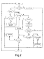
- control unit CU is programmed for adjusting lighting devices LD through voltage regulator VR by means of the following adjustment process.
- control unit CU checks in programmable timer PT whether at that moment lighting devices LD must be on, namely if a light timer LT is in an ON position.
- control unit CU checks whether lighting devices LD are already on, namely Vo>0.
- control unit CU ends the adjustment process (End), while in the negative (N) control unit CU checks whether light intensity LI is greater than maximum value Lmax (otherwise lower than minimum value Lmin).
Landscapes
- Circuit Arrangement For Electric Light Sources In General (AREA)
Priority Applications (1)
| Application Number | Priority Date | Filing Date | Title |
|---|---|---|---|
| EP08425482A EP2146554A1 (de) | 2008-07-14 | 2008-07-14 | Vorrichtung und Verfahren zur Regelung von wechselstromgespeisten Beleuchtungseinrichtungen |
Applications Claiming Priority (1)
| Application Number | Priority Date | Filing Date | Title |
|---|---|---|---|
| EP08425482A EP2146554A1 (de) | 2008-07-14 | 2008-07-14 | Vorrichtung und Verfahren zur Regelung von wechselstromgespeisten Beleuchtungseinrichtungen |
Publications (1)
| Publication Number | Publication Date |
|---|---|
| EP2146554A1 true EP2146554A1 (de) | 2010-01-20 |
Family
ID=40122371
Family Applications (1)
| Application Number | Title | Priority Date | Filing Date |
|---|---|---|---|
| EP08425482A Withdrawn EP2146554A1 (de) | 2008-07-14 | 2008-07-14 | Vorrichtung und Verfahren zur Regelung von wechselstromgespeisten Beleuchtungseinrichtungen |
Country Status (1)
| Country | Link |
|---|---|
| EP (1) | EP2146554A1 (de) |
Cited By (3)
| Publication number | Priority date | Publication date | Assignee | Title |
|---|---|---|---|---|
| EP2388471A1 (de) * | 2010-05-21 | 2011-11-23 | AEG Power Solutions B.V. | Schaltungsanordnung zur Folgesteuerung von Leistungsstellern mit einem Verteilen von Zündimpulsen |
| WO2012146877A1 (fr) * | 2011-04-29 | 2012-11-01 | DIRECT ePI | Dispositif d'eclairage public |
| EP2720514A1 (de) * | 2012-10-12 | 2014-04-16 | Tofco CPP Limited | Spannungsreglervorrichtung und Leistungsaufbereitungsvorrichtung mit einer derartigen Spannungsreglervorrichtung |
Citations (5)
| Publication number | Priority date | Publication date | Assignee | Title |
|---|---|---|---|---|
| US6191568B1 (en) * | 1999-01-14 | 2001-02-20 | Franco Poletti | Load power reduction control and supply system |
| WO2002065630A1 (en) * | 2001-02-13 | 2002-08-22 | Energy Saving 2000 S.A. | System for controlling electrical loads, particularly lighting units |
| EP1318702A1 (de) * | 2001-12-10 | 2003-06-11 | Bob Hammer Systems Solutions S.A. | Programmierbares System zur Stabilisierung und Regelung der Spannung insbesondere zur Verbesserung der Regelung von Lichtquellen wie Leuchtstofflampen und ähnlichen |
| US20050110416A1 (en) * | 2003-03-24 | 2005-05-26 | Lutron Electronics Co., Inc. | System to control daylight and artificial illumination and sun glare in a space |
| WO2006046264A1 (en) * | 2004-10-25 | 2006-05-04 | Silvano Varesi | Device for managing and controlling power supply of an electric apparatus, particularly a gas lamp |
-
2008
- 2008-07-14 EP EP08425482A patent/EP2146554A1/de not_active Withdrawn
Patent Citations (5)
| Publication number | Priority date | Publication date | Assignee | Title |
|---|---|---|---|---|
| US6191568B1 (en) * | 1999-01-14 | 2001-02-20 | Franco Poletti | Load power reduction control and supply system |
| WO2002065630A1 (en) * | 2001-02-13 | 2002-08-22 | Energy Saving 2000 S.A. | System for controlling electrical loads, particularly lighting units |
| EP1318702A1 (de) * | 2001-12-10 | 2003-06-11 | Bob Hammer Systems Solutions S.A. | Programmierbares System zur Stabilisierung und Regelung der Spannung insbesondere zur Verbesserung der Regelung von Lichtquellen wie Leuchtstofflampen und ähnlichen |
| US20050110416A1 (en) * | 2003-03-24 | 2005-05-26 | Lutron Electronics Co., Inc. | System to control daylight and artificial illumination and sun glare in a space |
| WO2006046264A1 (en) * | 2004-10-25 | 2006-05-04 | Silvano Varesi | Device for managing and controlling power supply of an electric apparatus, particularly a gas lamp |
Cited By (5)
| Publication number | Priority date | Publication date | Assignee | Title |
|---|---|---|---|---|
| EP2388471A1 (de) * | 2010-05-21 | 2011-11-23 | AEG Power Solutions B.V. | Schaltungsanordnung zur Folgesteuerung von Leistungsstellern mit einem Verteilen von Zündimpulsen |
| US8829867B2 (en) | 2010-05-21 | 2014-09-09 | Aeg Power Solutions B.V. | Device for the distribution of firing pulses circuit arrangement for the sequence control of power regulators |
| WO2012146877A1 (fr) * | 2011-04-29 | 2012-11-01 | DIRECT ePI | Dispositif d'eclairage public |
| FR2974617A1 (fr) * | 2011-04-29 | 2012-11-02 | DIRECT ePI | Dispositif d'eclairage public |
| EP2720514A1 (de) * | 2012-10-12 | 2014-04-16 | Tofco CPP Limited | Spannungsreglervorrichtung und Leistungsaufbereitungsvorrichtung mit einer derartigen Spannungsreglervorrichtung |
Similar Documents
| Publication | Publication Date | Title |
|---|---|---|
| CN102428759B (zh) | 用于管理照明负载的方法、系统及智能调光器 | |
| FI73114C (fi) | Kopplingsanordning foer att driva laogtrycksurladdningslampor, vilken anordning har en reglerbar ljusstroem. | |
| US5406174A (en) | Discharge lamp operating circuit with frequency control of dimming and lamp electrode heating | |
| RU2010119951A (ru) | Регулируемый трансформатор с переключаемыми ответлениями | |
| JP2012527073A5 (de) | ||
| US7786717B2 (en) | Transforming apparatus for automatically adjusting three-phase power supply voltage | |
| EP2146554A1 (de) | Vorrichtung und Verfahren zur Regelung von wechselstromgespeisten Beleuchtungseinrichtungen | |
| EP1452076B1 (de) | Programmierbares system zur spannungsstabilisierung und regelung insbesondere zur verbesserten verwaltung von beleuchtungseinheiten mit leuchtstofflampen und ähnlichem | |
| GB2477554A (en) | Lighting control system using first and second transformers | |
| EP0602719A1 (de) | Hochfrequenzumrichter für eine Entladungslampe mit vorheizbaren Elektroden | |
| EP2478748B1 (de) | Elektronisches vorschaltgerät mit dimmerschaltung | |
| RU2736627C2 (ru) | Газоразрядная лампа и устройство поддержания постоянной температуры для нее | |
| WO2013079962A2 (en) | Apparatus for controlling the voltage in an alternating current electricity supply | |
| GB2520336A (en) | Voltage regulation | |
| CN104582143A (zh) | 智能照明的调控方法 | |
| RU2364915C1 (ru) | Высокоточный электронный регулятор напряжения переменного тока | |
| WO2007034165A1 (en) | Methods and apparatus for constant-current regulation | |
| RU2245600C1 (ru) | Устройство для ступенчатого регулирования переменного напряжения | |
| JP2005292948A (ja) | 省エネ装置および配電線システム | |
| JPH09191574A (ja) | 節電装置 | |
| KR100709621B1 (ko) | 전압조절기능을 가진 가포화 리액터식 전력제어장치를내장한 가로등 분전함 | |
| KR200410123Y1 (ko) | 전압조절기능을 가진 가포화 리액터식 전력제어장치를내장한 가로등 분전함 | |
| RU55163U1 (ru) | Фазовый регулятор мощности | |
| CN104582141A (zh) | 照明系统的集中调光控制方法 | |
| KR200358976Y1 (ko) | 자동전력절감기 단상가로등용 |
Legal Events
| Date | Code | Title | Description |
|---|---|---|---|
| PUAI | Public reference made under article 153(3) epc to a published international application that has entered the european phase |
Free format text: ORIGINAL CODE: 0009012 |
|
| AK | Designated contracting states |
Kind code of ref document: A1 Designated state(s): AT BE BG CH CY CZ DE DK EE ES FI FR GB GR HR HU IE IS IT LI LT LU LV MC MT NL NO PL PT RO SE SI SK TR |
|
| AX | Request for extension of the european patent |
Extension state: AL BA MK RS |
|
| AKY | No designation fees paid | ||
| REG | Reference to a national code |
Ref country code: DE Ref legal event code: 8566 |
|
| STAA | Information on the status of an ep patent application or granted ep patent |
Free format text: STATUS: THE APPLICATION IS DEEMED TO BE WITHDRAWN |
|
| 18D | Application deemed to be withdrawn |
Effective date: 20100721 |