EP2147189B1 - Soupape à gaz et colonne de production dotée d'une soupape à gaz - Google Patents
Soupape à gaz et colonne de production dotée d'une soupape à gaz Download PDFInfo
- Publication number
- EP2147189B1 EP2147189B1 EP08766895.0A EP08766895A EP2147189B1 EP 2147189 B1 EP2147189 B1 EP 2147189B1 EP 08766895 A EP08766895 A EP 08766895A EP 2147189 B1 EP2147189 B1 EP 2147189B1
- Authority
- EP
- European Patent Office
- Prior art keywords
- valve
- production liner
- chamber
- flow
- shut
- Prior art date
- Legal status (The legal status is an assumption and is not a legal conclusion. Google has not performed a legal analysis and makes no representation as to the accuracy of the status listed.)
- Not-in-force
Links
- 238000004519 manufacturing process Methods 0.000 title claims description 87
- 239000012530 fluid Substances 0.000 claims description 31
- XLYOFNOQVPJJNP-UHFFFAOYSA-N water Substances O XLYOFNOQVPJJNP-UHFFFAOYSA-N 0.000 claims description 23
- 239000004576 sand Substances 0.000 claims description 17
- 210000001015 abdomen Anatomy 0.000 claims description 9
- 230000015572 biosynthetic process Effects 0.000 claims description 7
- 239000002253 acid Substances 0.000 claims description 5
- 230000002567 autonomic effect Effects 0.000 claims description 4
- 238000000605 extraction Methods 0.000 claims description 4
- 239000007788 liquid Substances 0.000 claims description 3
- 230000002250 progressing effect Effects 0.000 claims 1
- 238000007789 sealing Methods 0.000 description 6
- 230000000694 effects Effects 0.000 description 3
- 238000005516 engineering process Methods 0.000 description 3
- 239000006096 absorbing agent Substances 0.000 description 2
- 230000001419 dependent effect Effects 0.000 description 2
- 229920000642 polymer Polymers 0.000 description 2
- 239000005997 Calcium carbide Substances 0.000 description 1
- VYZAMTAEIAYCRO-UHFFFAOYSA-N Chromium Chemical compound [Cr] VYZAMTAEIAYCRO-UHFFFAOYSA-N 0.000 description 1
- 238000006073 displacement reaction Methods 0.000 description 1
- 238000002955 isolation Methods 0.000 description 1
- 239000000463 material Substances 0.000 description 1
- 239000000203 mixture Substances 0.000 description 1
- 230000035699 permeability Effects 0.000 description 1
- 239000006187 pill Substances 0.000 description 1
- 230000008092 positive effect Effects 0.000 description 1
- 230000000750 progressive effect Effects 0.000 description 1
- 230000002035 prolonged effect Effects 0.000 description 1
- CLZWAWBPWVRRGI-UHFFFAOYSA-N tert-butyl 2-[2-[2-[2-[bis[2-[(2-methylpropan-2-yl)oxy]-2-oxoethyl]amino]-5-bromophenoxy]ethoxy]-4-methyl-n-[2-[(2-methylpropan-2-yl)oxy]-2-oxoethyl]anilino]acetate Chemical compound CC1=CC=C(N(CC(=O)OC(C)(C)C)CC(=O)OC(C)(C)C)C(OCCOC=2C(=CC=C(Br)C=2)N(CC(=O)OC(C)(C)C)CC(=O)OC(C)(C)C)=C1 CLZWAWBPWVRRGI-UHFFFAOYSA-N 0.000 description 1
Images



Classifications
-
- F—MECHANICAL ENGINEERING; LIGHTING; HEATING; WEAPONS; BLASTING
- F16—ENGINEERING ELEMENTS AND UNITS; GENERAL MEASURES FOR PRODUCING AND MAINTAINING EFFECTIVE FUNCTIONING OF MACHINES OR INSTALLATIONS; THERMAL INSULATION IN GENERAL
- F16K—VALVES; TAPS; COCKS; ACTUATING-FLOATS; DEVICES FOR VENTING OR AERATING
- F16K17/00—Safety valves; Equalising valves, e.g. pressure relief valves
- F16K17/20—Excess-flow valves
- F16K17/34—Excess-flow valves in which the flow-energy of the flowing medium actuates the closing mechanism
-
- E—FIXED CONSTRUCTIONS
- E21—EARTH OR ROCK DRILLING; MINING
- E21B—EARTH OR ROCK DRILLING; OBTAINING OIL, GAS, WATER, SOLUBLE OR MELTABLE MATERIALS OR A SLURRY OF MINERALS FROM WELLS
- E21B34/00—Valve arrangements for boreholes or wells
- E21B34/06—Valve arrangements for boreholes or wells in wells
- E21B34/08—Valve arrangements for boreholes or wells in wells responsive to flow or pressure of the fluid obtained
-
- Y—GENERAL TAGGING OF NEW TECHNOLOGICAL DEVELOPMENTS; GENERAL TAGGING OF CROSS-SECTIONAL TECHNOLOGIES SPANNING OVER SEVERAL SECTIONS OF THE IPC; TECHNICAL SUBJECTS COVERED BY FORMER USPC CROSS-REFERENCE ART COLLECTIONS [XRACs] AND DIGESTS
- Y10—TECHNICAL SUBJECTS COVERED BY FORMER USPC
- Y10T—TECHNICAL SUBJECTS COVERED BY FORMER US CLASSIFICATION
- Y10T137/00—Fluid handling
- Y10T137/7722—Line condition change responsive valves
- Y10T137/7837—Direct response valves [i.e., check valve type]
Definitions
- the present invention generally relates to a valve, and to a production liner having a number of such valves.
- a valve arranged to automatically shut off the flow of fluid into a production liner for extraction of oil and gas in the event of a gas break-through, by the valve comprising a valve seat containing at least one central inflow channel and one or more outflow channels from the valve. It also generally relates to a production liner comprising a valve.
- a completion string consists of many production tubes, each measuring 12 meters, which are screwed together.
- sand screens have been fixed to prevent sand from entering into the oil/production facility.
- swell packers sealing against the formation. The purpose is to divide the production liner into sections that can be regarded as separate production environments, i.e. prevent the multi-fluid liquid and gas to advance from one section to another except through the production liner.
- Embodiments of the present valve shall only shut off exactly where there is a breakthrough (the individual 12 meter joint of production liner) so that one may produce in the remaining part of the production liner and at least in the section that may be suffering from gas breakthrough in the event that the gas moves on the exterior of the liner.
- the shut-off shall basically take place automatically, i.e. the valve shall not be controlled from surface. Technology may be built in to enable the valve to tell the surface that it has been shut due to gas breakthrough.
- ICD Inflow Control Device
- kill filter Today's technology within this area consists of sand screens, ICD (Inflow Control Device) and a kill filter.
- the oil enters the production liner via the kill filter.
- ICD is a kind of pressure absorber that distributes the pressure across the production liner to avoid having to produce empty at one part whilst the differential pressure is very high at other parts of the liner. Such an absorbing or alignment is also fortunate to avoid damage to the sand screens and will also prevent that the formation falls in over the liner.
- the current ICD may be kept as an assurance, but embodiments of the present valve will have a much better ICD-characteristic (distribution capability), since it is a much more powerful pressure absorber/pressure equalizer than the current ICD.
- Embodiments of the present valve use the Bernoulli-principle for high velocity flow over a surface/obstruction (disk).
- the Bernoulli-principle is being used in a number of applications and shows that a plate/disk is pulled against a seat due to the negative pressure arising. Due to the fact that the sealing is not absolute, the pressure will eventually leak to the other side of the disk so that a new attraction force is built and the sealing has been re-established. This means that the solution will be dynamic and react based on the composition of the fluid and/or gas flowing over it. The less viscosity, the higher and more immediate sealing will arise. Trials have shown that more or less all gas is stopped by a valve using the Bernoulli principle. In addition, such a valve has a positive effect on water breakthrough so that produced water is reduced simultaneously.
- inventions of the present valve is that it is curved in its design so that it can be placed on the exterior of the production liner and as such supports the current technology guiding the oil along the exterior of the liner until it is permitted to enter the interior through longitudinal slots - the so-called kill filter.
- An autonomous valve will according to an embodiment of the invention be dynamic and will uphold a given characteristic for multiphase flow of fluid without having to be controlled from the surface. Any valve being exposed to gas will immediately shut off based on the given characteristic. The gas consequently has to take another path, or it is under control. Normally it will penetrate further to another valve within the same zone segregated section so that this valve also closes. The use of zone isolation (swell packers) will prevent the gas from flowing outside of the section so that oil can be produced from all the valves only exposed to oil and/or water.
- the characteristic against water is set to restrict water more than oil.
- each liner joint When all oil has been produced, each liner joint may be opened so that the gas can be produced when desired. This opening will take place by opening of a valve in the chamber ahead of the valve which in turn will let the oil enter directly into the basepipe.
- the valve will according to an embodiment of the invention will not create any obstacles inside of the production liner so that the annulus flow may pass unhindered and that interventions can be performed.
- WO 2007/027617 A2 As examples of prior art, the following documents are referred to: WO 2007/027617 A2 , US 7,185,706 B2 , NO 305.376 B1 , WO 97/38248 A1 , WO 2006/015277 A1 (which shows a valve and production string, and specifically describes a downhole sand screen and inflow control device with a gas or water shut-off feature that can be operated mechanically or hydraulically from the surface of the well), NO 306.127 B1 , WO 00/63530 A1 and US 6,786,285 B2 .
- Document WO2008/004875 A1 is prior art according to Article 54(3) EPC, this document shows a valve of relatively flat shape.
- a valve embodiment is constructed with a curved design equal to the shape of the outer diameter of the production liner, and is placed on the outside of the production liner, and in that a rectangular shut off disk with the same curving is arranged in the valve, in the flowing path of the liquid flow, to cause a high velocity flow over the shut off disk's surface against the valve seat, by which the shut off disk is adapted to seal against said valve seat dependant on the differential pressure being produced by the viscosity of the passing flow.
- the shut off disk may be placed in a rectangular chamber in the valve, and at least one of the central inflow channels can be an open notch covering at least half of the length of the chamber. Further, the central inflow channel's open notch in the bottom may be shaped with walls shaped as an open rectangle, by which the walls thereafter leads into a tract, and the outflow channels can be designed in a rectangular form and placed on each side of the central inflow channel.
- the valve will preferably comprise a belly shaped valve section having inward protruding folds on the top, where the shut off disk is contained in said belly shaped chamber, and an upper valve section with the said seat and outflow channel, for placement over the open belly shape, wherein the outflow channels are provided between the upper and lower sections of the valve.
- the valve can be placed in a separate valve housing, or the production liner can act as the bottom side and the surrounding housing can constitute the upper side of the valve housing.
- the valve is preferable a dynamic valve designed to uphold a given characteristic for multiphase fluid, independent from external control from surface.
- a production liner embodiment for the exploration of oil and gas comprises at least one surrounding sand screen and one adjacent, surrounding inflow device, arranged to control and lead the flow of fluid into the production liner, wherein the inflow device comprises a number of chambers, in which there are flow channels between the chambers, as a pre-chamber is arranged to receive the fluid flow from the sand screen, an intermediary chamber is arranged to receive the fluid flow from the pre-chamber and automatically shut off gas further into the production liner in the event of gas breakthrough, where the valve chamber comprises a number of valves as described above, and a post chamber arranged to control and direct the fluid into the production liner.
- the valve chamber may comprise a number of supporting rings fixed to the production liner, where a number of said valves are arranged in a mutual distance from each other on the circumference of the production liner between said supporting rings and mounted inside of a surrounding housing.
- Said supporting rings may consist of two circular rings mounted on the production liner and which are totally sealed, arranged to direct the flow of fluid and to keep the valves in place, since the valves have been mounted between the rings.
- the flow shall preferably enter through the channels in the first supporting ring and thereafter flow through channels in the second supporting ring, to the post chamber.
- the pre-chamber can further comprise an acid plug arranged to open for the production of gas after the oil has been produced, and/or may comprise a one-directional valve permitting for killing against the formation.
- the post chamber can be arranged to direct the fluid into the production liner through a kill filter.
- the production liner can be equipped with an autonomic water shut off valve.
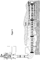
- Figure 1 show a completion string in a formation for production of oil, comprising production liner 12 screwed together.
- production liner 12 screwed together.
- sand screens 14 have been mounted to prevent sand from entering the oil.
- swell packers 15 have been placed to split the production liner into sections so that each section can be treated as separate production environments, i.e. that the gas is not permitted to advance from one section to another unless it happens through the production liner.
- a production liner 12 is shown with an inflow control device 10 according to an embodiment of the invention. Adjacent the inflow control device 10, a sand filter 14 is arranged around the production liner.
- the inflow control device 10 may comprise ICD and gas shut-off valve, kill filter or slots, acid plug 50 and a one-directional valve 52 to open for killing against the formation.
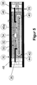
- the inflow control device 10 can be designed having three chambers 20, 22, 24. Each of the chambers is separated by totally sealed sections so that the multi fluid flow basically can only flow through the flow channels in the device 10.
- the flow direction is from the pre-chamber 20 to the valve chamber 22 and to the post chamber 24.
- the fluid enters into the pre- chamber from the inside of the sand screen 14 and flow through the ring-room between the sand screen 14 and the production liner 12. Thereafter the flow is directed through the channels in the first supporting ring 19 and into the valve 30 itself. Thereafter the flow preferably flows out on the sides to small intermediate chambers 26a, 26b and then through the channels in second supporting ring to the post chamber 24.
- the fluid shall only be directed into the production liner 12, for example through the kill filter. If desired a standard channel-ICD may be mounted in front.
- an acidizing plug 50 may be placed to allow for the opening of gas production after all of the oil has been produced.
- An acid pill may be used to open it by running interventions.
- a one-directional valve 52 available from the market, may be used.
- a new plug can be designed to un-hatch upon a specific counter pressure from the inside of the production liner. None of the known solutions introduced, have solved this problem. It is also necessary to be able to kill the well both against the inside and against the formation. Embodiments of the present valve will accommodate both. The valve will in fact allow fluid to flow both ways and should in theory make a one-directional valve superfluous.
- the fluid enters the pre-chamber from underneath the sand screen and flows into the ring room between the sand screen and the production liner. Thereafter it flows through first supporting ring and into the valve itself.
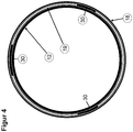
- the support ring/frame will for example consist of two complete rings 19 which are fixed to the production liner 12 and which are totally sealed (preferably welded onto the liner). These will lead the flow of fluid and keep the valves in place.
- the rings should preferably be manufactured in the same material as the production liner (13% Chrome).
- the valves 30 shall be mounted inside the frame (between the rings 19) and here one may place as many valve as desired (normally between 1 and 4). If one chooses only 1 or 2, the vertical orientation of the liner could potentially become a topic, so 3 or more are recommended.
- the top and bottom of the chambers are consequently composed by the housing 18 (which is screwed on) and the base pipe itself.
- the supporting rings can be made as slim or wide as desired to obtain the required strength and sealing. On the rings it should be constructed gas-tight threads (interfacing with the housing) to avoid having to use polymers. Since the supporting rings will preferably be welded onto the liner, the liner would have to be heat treated afterwards and this is why it is desired to avoid having to use polymers.
- the flow enters through the first supporting ring and thereafter through the valve 30 and out through the second and last supporting ring. The flow is directed to the side in some small intermediary chambers and thereafter through the channels in the second supporting ring into the post chamber 24.
- the fluid shall only be directed into the production liner 12, potentially through the kill filter.
- the fluid can also flow into the production liner 12 through holes if it is not desired to have kill filter.
- valve 30 (shown in a flat configuration for illustration purpose) is shown for a production liner 12, which automatically may shut off the flow of fluid into the production liner 12 in the event of gas breakthrough.
- the valve 30 is arranged outside on the production liner and is constructed with a curved design equal to the shape of the outer diameter of the production liner (as shown in figure 4 ).
- the valve 30 comprises a valve seat 32 containing at least one central inflow channel 34 and one or more outflow channels 36, 38 from the valve 30.
- a rectangular, basically flat shut-off disk 40 preferably having a curvature harmonised with the outer diameter of the production liner 12 to produce high velocity flow of fluid over the surface of the disk 40a against the valve seating 32.
- the disk can potentially be shaped without the curvature, i.e. not following the outer diameter of the production liner.
- the shut-off disk 40 will thereby seal against the valve seating 32 dependant on the differential pressure arising dependant on the viscosity of the flow medium, following the Bernoulli-principle which causes the disk 40 to be pulled against the seating 32 due to the negative pressure that arises.
- the shut-off valve 32 is placed in a basically rectangular chamber 42 within the valve 30, where the chamber 42 has been designed somewhat larger than the disk 40.
- the central inflow channel 34 is in the shown example an open notch ranging in most (at least half of) the length of the chamber. In the bottom part the open notch is shaped with walls in an open rectangular shape 34a, and the side walls exit in a funnel shape 34b. Further, the valves output channels 36, 38 are preferable rectangular shaped, and provided on each side of the central inflow channel 34.
- the valve 30 comprises a lower belly shaped valve section 44 containing inward protruding folds 46, 48, to permit the shut off disk 40 to be placed in the belly shape.
- the valve 30 further comprises an upper valve part 50 with the valve seat 32, with inflow channel 34, to be placed over the belly shape.
- the outflow channels 36, 38 can thereby be placed between the upper and the lower valve sections 44, 50.
- the valve 30 may be arranged in a separate valve housing 28, or the production liner 12 could constitute the bottom and the housing 18 can constitute the top of the valve housing.
- a production liner according to an embodiment of the invention can also be equipped with a water shut off valve (not shown).
- a water shut off valve (not shown).
- one or more valves covering both aspects will be the ideal and complete solution. If support for both aspects can be achieved, this will rule out all single based solutions.
- a water shut off valve can be provided, which gives permanent shut off after being exposed for water in a non-inessential period.
- the time before the valve closes can be controlled by designing of a locking mechanism, for example provided in calcium carbide.
- a combination of gas shut off valves and water shut off valves connected in series will solve both water- and gas shut off.
- the water shut off valve can be placed after the gas shut off valve with ICD effect.
Landscapes
- Engineering & Computer Science (AREA)
- Mining & Mineral Resources (AREA)
- Geology (AREA)
- General Engineering & Computer Science (AREA)
- Life Sciences & Earth Sciences (AREA)
- Geochemistry & Mineralogy (AREA)
- Fluid Mechanics (AREA)
- Environmental & Geological Engineering (AREA)
- Physics & Mathematics (AREA)
- Mechanical Engineering (AREA)
- General Life Sciences & Earth Sciences (AREA)
- Lift Valve (AREA)
- Feeding And Controlling Fuel (AREA)
- Devices And Processes Conducted In The Presence Of Fluids And Solid Particles (AREA)
- Valve Housings (AREA)
- Structures Of Non-Positive Displacement Pumps (AREA)
- Details Of Valves (AREA)
- Check Valves (AREA)
Claims (14)
- Soupape (30) agencée pour arrêter automatiquement l'écoulement de fluide dans une colonne perdue de production (12) pour l'extraction de pétrole et de gaz en cas de percée de gaz, moyennant quoi la soupape (30) comprend un siège de soupape (32) contenant au moins un canal d'entrée central (34) et un ou plusieurs canaux de sortie (36, 38) de la soupape (30) dans ladite une colonne perdue de production (12), caractérisée en ce que la soupape (30) est fabriquée avec une conception incurvée adaptée pour être égale à la forme du diamètre externe d'une colonne perdue de production (12) et peut ensuite être placée à l'extérieur de ladite colonne perdue de production (12), et en ce qu'un corps d'arrêt ayant une surface, est agencé dans la soupape (30), dans la trajectoire d'écoulement de l'écoulement de liquide, pour provoquer un écoulement à grande vitesse sur la surface (40a) du corps d'arrêt contre le siège de soupape (32), dans laquelle le corps d'arrêt est adapté pour réaliser une étanchéité contre ledit siège de soupape (32) dépendant de la pression différentielle produite dans le flux passant selon le principe de Bernouli, dans laquelle le corps d'arrêt est une plaque rectangulaire ou un disque (40).
- Soupape selon la revendication 1, caractérisée en ce que le corps d'arrêt est une plaque rectangulaire et est agencé dans une chambre rectangulaire (42) à l'intérieur de la soupape (30), et dans laquelle le au moins un canal d'entrée central (34) est une encoche ouverte faisant saillie au moins à mi-chemin de la chambre.
- Soupape selon la revendication 2, caractérisée en ce que l'encoche ouverte du canal d'entrée central (34) dans le fond est formée par des parois latérales d'une forme rectangulaire ouverte (34a), moyennant quoi les parois latérales existent ensuite selon une forme d'entonnoir (34b) et ce que les canaux de sortie (36, 38) sont conçus avec une forme rectangulaire et sont placés de chaque côté du canal d'entrée central.
- Soupape selon la revendication 2 ou 3, caractérisé en ce que la soupape (30) comprend un partie inférieure de soupape en forme de ventre (44) contenant des plis supérieurs en saillie vers l'intérieur (46, 48), dans laquelle le corps d'arrêt est une plaque contenue dans ladite forme de ventre, et une partie supérieure de soupape (50) comprenant ledit siège (32) et le canal d'entrée (34), pour se positionner au-dessus de la forme de ventre ouverte, moyennant quoi les canaux de sortie (36, 38) sont prévus entre lesdites parties supérieure et inférieure de soupape (44, 50).
- Soupape selon la revendication 4, caractérisée en ce que la soupape (30) comprend une chambre de soupape (38) séparée ou un logement (18) définissant une partie supérieure de la soupape, dans laquelle la colonne perdue de production (12), lorsque la soupape est positionnée à l'extérieur de la colonne perdue de production (12), présente un fond de la chambre de soupape.
- Soupape selon les revendications 2 à 5, caractérisée en ce que la soupape (30) est une soupape dynamique agencée pour maintenir une caractéristique donnée pour un écoulement multiphase de fluide, indépendant d'un contrôle externe de la surface.
- Colonne perdue de production (30) pour l'extraction de pétrole et de gaz, comprenant au moins un crible à sable périphérique (14) et au moins un dispositif d'entrée (10) adjacent agencé pour contrôler et diriger l'écoulement de fluide dans la colonne perdue de production, caractérisée en ce que le dispositif d'entrée (10) comprend un certain nombre de chambres (20, 22, 24), où il y a des canaux d'écoulement (20a, 22a, 22b) entre les chambres, dans laquelle une préchambre (20) est agencée pour recevoir l'écoulement de fluide depuis le crible à sable (14), une chambre de soupape intermédiaire (22) est agencée pour recevoir l'écoulement de fluide depuis la préchambre (20) et pour empêcher automatiquement la progression du gaz dans la colonne perdue de production (12) en cas de percée de gaz, moyennant quoi la chambre de soupape (22) comprend un certain nombre de soupapes (30) selon une ou plusieurs des revendications 1 à 6, et une post-chambre (24) qui est agencée pour recevoir l'écoulement de fluide de la chambre de soupape (22) et pour contrôler et diriger l'écoulement de fluide dans la colonne perdue de production (12).
- Colonne perdue de production selon la revendication 7, caractérisée en ce que la chambre de soupape (22) comprend un certain nombre d'anneaux de support (19) fixés sur la colonne perdue de production, où un certain nombre desdites soupapes (30) sont placées avec une distance mutuelle sur le diamètre externe de la colonne perdue de production (12) entre lesdits anneaux de support (19) et fixées à l'intérieur d'un logement périphérique (18).
- Colonne perdue de production selon la revendication 8, caractérisée en ce que les anneaux de support (19) constituent deux anneaux complets fixés sur la colonne perdue de production et sont totalement scellés, et sont agencés pour diriger l'écoulement de fluide et pour maintenir les soupapes (30) en place, en ce que les soupapes sont positionnées entre les anneaux de support.
- Colonne perdue de production selon la revendication 9, caractérisée en ce que le fluide entre dans les canaux dans le premier anneau de support et ensuite dans les canaux dans le second anneau de support jusqu'à la post-chambre (24).
- Colonne perdue de production selon la revendication 7, caractérisée en ce que la préchambre comprend un bouchon d'acide (50) agencé pour s'ouvrir pour la production de gaz après l'extraction de tout le pétrole disponible.
- Colonne perdue de production selon la revendication 7, caractérisée en ce que la préchambre contient une valve unidirectionnelle (52) agencée pour s'ouvrir pour l'injection contre la formation.
- Colonne perdue de production selon la revendication 7, caractérisée en ce que la post-chambre est agencée afin de diriger l'écoulement de fluide dans la colonne perdue de production à travers un filtre d'injection.
- Colonne perdue de production selon la revendication 7, caractérisée en ce que la colonne perdue de production est équipée avec une soupape de fermeture d'eau automatique.
Applications Claiming Priority (2)
| Application Number | Priority Date | Filing Date | Title |
|---|---|---|---|
| NO20072639A NO326258B1 (no) | 2007-05-23 | 2007-05-23 | Ventil for et produksjonsror, og produksjonsror med samme |
| PCT/NO2008/000177 WO2008143522A1 (fr) | 2007-05-23 | 2008-05-22 | Soupape à gaz et colonne de production dotée d'une soupape à gaz |
Publications (3)
| Publication Number | Publication Date |
|---|---|
| EP2147189A1 EP2147189A1 (fr) | 2010-01-27 |
| EP2147189A4 EP2147189A4 (fr) | 2011-11-02 |
| EP2147189B1 true EP2147189B1 (fr) | 2018-12-05 |
Family
ID=40020120
Family Applications (1)
| Application Number | Title | Priority Date | Filing Date |
|---|---|---|---|
| EP08766895.0A Not-in-force EP2147189B1 (fr) | 2007-05-23 | 2008-05-22 | Soupape à gaz et colonne de production dotée d'une soupape à gaz |
Country Status (14)
| Country | Link |
|---|---|
| US (1) | US8534355B2 (fr) |
| EP (1) | EP2147189B1 (fr) |
| CN (1) | CN101688440B (fr) |
| AP (1) | AP2009005051A0 (fr) |
| AU (1) | AU2008253825B2 (fr) |
| BR (1) | BRPI0811916B1 (fr) |
| CA (1) | CA2685946C (fr) |
| EA (1) | EA015218B1 (fr) |
| EC (1) | ECSP099731A (fr) |
| MA (1) | MA31449B1 (fr) |
| MX (1) | MX357339B (fr) |
| NO (1) | NO326258B1 (fr) |
| TN (1) | TN2009000453A1 (fr) |
| WO (1) | WO2008143522A1 (fr) |
Families Citing this family (13)
| Publication number | Priority date | Publication date | Assignee | Title |
|---|---|---|---|---|
| AU2008305337B2 (en) | 2007-09-25 | 2014-11-13 | Schlumberger Technology B.V. | Flow control systems and methods |
| NO338993B1 (no) * | 2008-11-18 | 2016-11-07 | Statoil Petroleum As | Strømningsstyringsinnretning og fremgangsmåte for å kontrollere fluidstrømningen ved olje- og/eller gassproduksjon |
| NO336424B1 (no) | 2010-02-02 | 2015-08-17 | Statoil Petroleum As | Strømningsstyringsanordning, strømningsstyringsfremgangsmåte og anvendelse derav |
| US8544554B2 (en) * | 2010-12-14 | 2013-10-01 | Halliburton Energy Services, Inc. | Restricting production of gas or gas condensate into a wellbore |
| WO2012095183A1 (fr) * | 2011-01-14 | 2012-07-19 | Statoil Petroleum As | Vanne autonome |
| NO340334B1 (no) * | 2013-06-21 | 2017-04-03 | Statoil Petroleum As | Strømningsstyringsanordning, strømningsstyrings-fremgangsmåte og anvendelse derav |
| AU2014296122B2 (en) | 2013-07-31 | 2017-09-21 | Schlumberger Technology B.V. | Sand control system and methodology |
| GB201418062D0 (en) * | 2014-10-13 | 2014-11-26 | Flotech Holdings Bvi Ltd | Downhole flow control device |
| US10597984B2 (en) | 2014-12-05 | 2020-03-24 | Schlumberger Technology Corporation | Inflow control device |
| US10871057B2 (en) | 2015-06-30 | 2020-12-22 | Schlumberger Technology Corporation | Flow control device for a well |
| GB2559343B (en) * | 2017-01-31 | 2020-06-24 | Swellfix Uk Ltd | Downhole flow control device and method. |
| CN112127859B (zh) * | 2020-11-02 | 2024-11-19 | 沧州瑞泰石油机械有限公司 | 双向控流阀、控水筛管以及完井管串 |
| WO2022240589A1 (fr) | 2021-05-12 | 2022-11-17 | Schlumberger Technology Corporation | Système et procédé de dispositif de régulation d'écoulement entrant autonome |
Family Cites Families (26)
| Publication number | Priority date | Publication date | Assignee | Title |
|---|---|---|---|---|
| US3536090A (en) | 1968-05-09 | 1970-10-27 | Yarway Corp | Thermodynamic steam trap |
| CA945862A (en) | 1971-04-16 | 1974-04-23 | Velan Engineering Ltd. | Thermodynamic steam trap |
| US4387732A (en) | 1977-08-30 | 1983-06-14 | Ywhc, Inc. | Steam trap including interchangeable body member and insert assembly |
| GB2163832B (en) | 1984-08-29 | 1988-02-10 | Spirax Sarco Ltd | Thermodynamic steam trap valve discs |
| NO306127B1 (no) | 1992-09-18 | 1999-09-20 | Norsk Hydro As | Fremgangsmate og produksjonsror for produksjon av olje eller gass fra et olje- eller gassreservoar |
| FI104756B (fi) | 1993-09-20 | 2000-03-31 | Caroma Ind Ltd | Paineeltaan ja virtaukseltaan tasapainotettu venttiili |
| WO1997038248A1 (fr) * | 1996-04-10 | 1997-10-16 | Applied Power Inc. | Clapet bidirectionnel |
| US5896928A (en) | 1996-07-01 | 1999-04-27 | Baker Hughes Incorporated | Flow restriction device for use in producing wells |
| US5803179A (en) * | 1996-12-31 | 1998-09-08 | Halliburton Energy Services, Inc. | Screened well drainage pipe structure with sealed, variable length labyrinth inlet flow control apparatus |
| US6367547B1 (en) * | 1999-04-16 | 2002-04-09 | Halliburton Energy Services, Inc. | Downhole separator for use in a subterranean well and method |
| US6371210B1 (en) * | 2000-10-10 | 2002-04-16 | Weatherford/Lamb, Inc. | Flow control apparatus for use in a wellbore |
| NO314701B3 (no) | 2001-03-20 | 2007-10-08 | Reslink As | Stromningsstyreanordning for struping av innstrommende fluider i en bronn |
| US6644412B2 (en) | 2001-04-25 | 2003-11-11 | Weatherford/Lamb, Inc. | Flow control apparatus for use in a wellbore |
| NO313895B1 (no) * | 2001-05-08 | 2002-12-16 | Freyer Rune | Anordning og fremgangsmÕte for begrensning av innströmning av formasjonsvann i en brönn |
| GB2376488B (en) * | 2001-06-12 | 2004-05-12 | Schlumberger Holdings | Flow control regulation method and apparatus |
| AU2004225541B2 (en) * | 2003-03-28 | 2008-03-13 | Shell Internationale Research Maatschappij B.V. | Surface flow controlled valve and screen |
| US7409999B2 (en) * | 2004-07-30 | 2008-08-12 | Baker Hughes Incorporated | Downhole inflow control device with shut-off feature |
| US7290606B2 (en) * | 2004-07-30 | 2007-11-06 | Baker Hughes Incorporated | Inflow control device with passive shut-off feature |
| US7537056B2 (en) * | 2004-12-21 | 2009-05-26 | Schlumberger Technology Corporation | System and method for gas shut off in a subterranean well |
| CN2782925Y (zh) * | 2005-03-03 | 2006-05-24 | 岳玉全 | 一种石油开采地面集输系统 |
| CN2782924Y (zh) * | 2005-04-20 | 2006-05-24 | 中国石油化工股份有限公司中原油田分公司采油工程技术研究院 | 耐高压气举阀 |
| US8453746B2 (en) * | 2006-04-20 | 2013-06-04 | Halliburton Energy Services, Inc. | Well tools with actuators utilizing swellable materials |
| EA013497B1 (ru) * | 2006-07-07 | 2010-04-30 | Статоилхюдро Аса | Способ для регулирования расхода и автономные клапан или устройство для регулирования расхода |
| US20080041580A1 (en) * | 2006-08-21 | 2008-02-21 | Rune Freyer | Autonomous inflow restrictors for use in a subterranean well |
| US7699101B2 (en) * | 2006-12-07 | 2010-04-20 | Halliburton Energy Services, Inc. | Well system having galvanic time release plug |
| US7828067B2 (en) * | 2007-03-30 | 2010-11-09 | Weatherford/Lamb, Inc. | Inflow control device |
-
2007
- 2007-05-23 NO NO20072639A patent/NO326258B1/no not_active IP Right Cessation
-
2008
- 2008-05-22 AP AP2009005051A patent/AP2009005051A0/en unknown
- 2008-05-22 MX MX2009012578A patent/MX357339B/es active IP Right Grant
- 2008-05-22 WO PCT/NO2008/000177 patent/WO2008143522A1/fr not_active Ceased
- 2008-05-22 EA EA200901524A patent/EA015218B1/ru not_active IP Right Cessation
- 2008-05-22 CN CN2008800171192A patent/CN101688440B/zh not_active Expired - Fee Related
- 2008-05-22 US US12/600,782 patent/US8534355B2/en not_active Expired - Fee Related
- 2008-05-22 CA CA2685946A patent/CA2685946C/fr not_active Expired - Fee Related
- 2008-05-22 EP EP08766895.0A patent/EP2147189B1/fr not_active Not-in-force
- 2008-05-22 BR BRPI0811916A patent/BRPI0811916B1/pt not_active IP Right Cessation
- 2008-05-22 AU AU2008253825A patent/AU2008253825B2/en not_active Ceased
-
2009
- 2009-10-30 TN TNP2009000453A patent/TN2009000453A1/fr unknown
- 2009-11-12 EC ECSP099731 patent/ECSP099731A/es unknown
- 2009-12-16 MA MA32425A patent/MA31449B1/fr unknown
Non-Patent Citations (1)
| Title |
|---|
| None * |
Also Published As
| Publication number | Publication date |
|---|---|
| ECSP099731A (es) | 2010-02-26 |
| CA2685946C (fr) | 2016-10-11 |
| US8534355B2 (en) | 2013-09-17 |
| CN101688440A (zh) | 2010-03-31 |
| BRPI0811916A2 (pt) | 2014-11-18 |
| CN101688440B (zh) | 2012-10-10 |
| WO2008143522A1 (fr) | 2008-11-27 |
| MX2009012578A (es) | 2010-02-12 |
| EP2147189A1 (fr) | 2010-01-27 |
| MA31449B1 (fr) | 2010-06-01 |
| US20100186832A1 (en) | 2010-07-29 |
| AU2008253825A1 (en) | 2008-11-27 |
| AU2008253825B2 (en) | 2011-10-27 |
| NO20072639A (no) | 2008-10-27 |
| BRPI0811916B1 (pt) | 2018-12-26 |
| EA015218B1 (ru) | 2011-06-30 |
| CA2685946A1 (fr) | 2008-11-27 |
| EA200901524A1 (ru) | 2010-04-30 |
| EP2147189A4 (fr) | 2011-11-02 |
| MX357339B (es) | 2018-07-04 |
| AP2009005051A0 (en) | 2009-12-31 |
| NO326258B1 (no) | 2008-10-27 |
| TN2009000453A1 (en) | 2011-03-31 |
Similar Documents
| Publication | Publication Date | Title |
|---|---|---|
| EP2147189B1 (fr) | Soupape à gaz et colonne de production dotée d'une soupape à gaz | |
| AU2009296846B2 (en) | Pressure relieving transition joint | |
| US20110056700A1 (en) | System and method for recompletion of old wells | |
| US9664014B2 (en) | Method and system for segmental flow control in oil-gas well | |
| US12353228B2 (en) | Flow control device and method | |
| CN102859113A (zh) | 控制井下流体流速的管状嵌入式喷嘴组件 | |
| EP4471530A2 (fr) | Dispositif et procédé de régulation de débit | |
| CN102041983A (zh) | 带有控流能力的控砂滤筛组件 | |
| AU2015284356B2 (en) | Hydraulic lock compensating dummy valve | |
| US20220195840A1 (en) | Density constant flow device with flexible tube | |
| US20160186500A1 (en) | Injectable inflow control assemblies | |
| AU2012249434A1 (en) | Annular pressure release sub | |
| US11702906B2 (en) | Density constant flow device using a changing overlap distance | |
| AU2016238961B2 (en) | Pressure relieving transition joint | |
| OA21601A (en) | A Flow Control Device And Method. | |
| CN104797775A (zh) | 用于压裂的井眼的增产方法 |
Legal Events
| Date | Code | Title | Description |
|---|---|---|---|
| PUAI | Public reference made under article 153(3) epc to a published international application that has entered the european phase |
Free format text: ORIGINAL CODE: 0009012 |
|
| 17P | Request for examination filed |
Effective date: 20091029 |
|
| AK | Designated contracting states |
Kind code of ref document: A1 Designated state(s): AT BE BG CH CY CZ DE DK EE ES FI FR GB GR HR HU IE IS IT LI LT LU LV MC MT NL NO PL PT RO SE SI SK TR |
|
| AX | Request for extension of the european patent |
Extension state: AL BA MK RS |
|
| DAX | Request for extension of the european patent (deleted) | ||
| RAP1 | Party data changed (applicant data changed or rights of an application transferred) |
Owner name: STATOIL PETROLEUM AS |
|
| A4 | Supplementary search report drawn up and despatched |
Effective date: 20110930 |
|
| RIC1 | Information provided on ipc code assigned before grant |
Ipc: E21B 34/08 20060101AFI20110926BHEP Ipc: F16K 17/34 20060101ALI20110926BHEP Ipc: E21B 43/08 20060101ALI20110926BHEP |
|
| 17Q | First examination report despatched |
Effective date: 20111012 |
|
| STAA | Information on the status of an ep patent application or granted ep patent |
Free format text: STATUS: EXAMINATION IS IN PROGRESS |
|
| GRAP | Despatch of communication of intention to grant a patent |
Free format text: ORIGINAL CODE: EPIDOSNIGR1 |
|
| STAA | Information on the status of an ep patent application or granted ep patent |
Free format text: STATUS: GRANT OF PATENT IS INTENDED |
|
| INTG | Intention to grant announced |
Effective date: 20180622 |
|
| GRAS | Grant fee paid |
Free format text: ORIGINAL CODE: EPIDOSNIGR3 |
|
| GRAJ | Information related to disapproval of communication of intention to grant by the applicant or resumption of examination proceedings by the epo deleted |
Free format text: ORIGINAL CODE: EPIDOSDIGR1 |
|
| GRAL | Information related to payment of fee for publishing/printing deleted |
Free format text: ORIGINAL CODE: EPIDOSDIGR3 |
|
| STAA | Information on the status of an ep patent application or granted ep patent |
Free format text: STATUS: EXAMINATION IS IN PROGRESS |
|
| GRAR | Information related to intention to grant a patent recorded |
Free format text: ORIGINAL CODE: EPIDOSNIGR71 |
|
| INTC | Intention to grant announced (deleted) | ||
| STAA | Information on the status of an ep patent application or granted ep patent |
Free format text: STATUS: GRANT OF PATENT IS INTENDED |
|
| GRAA | (expected) grant |
Free format text: ORIGINAL CODE: 0009210 |
|
| INTG | Intention to grant announced |
Effective date: 20181024 |
|
| RIN1 | Information on inventor provided before grant (corrected) |
Inventor name: JOHANNESEN, EILIF, H. |
|
| GRAA | (expected) grant |
Free format text: ORIGINAL CODE: 0009210 |
|
| STAA | Information on the status of an ep patent application or granted ep patent |
Free format text: STATUS: THE PATENT HAS BEEN GRANTED |
|
| AK | Designated contracting states |
Kind code of ref document: B1 Designated state(s): AT BE BG CH CY CZ DE DK EE ES FI FR GB GR HR HU IE IS IT LI LT LU LV MC MT NL NO PL PT RO SE SI SK TR |
|
| REG | Reference to a national code |
Ref country code: GB Ref legal event code: FG4D |
|
| REG | Reference to a national code |
Ref country code: CH Ref legal event code: EP |
|
| REG | Reference to a national code |
Ref country code: AT Ref legal event code: REF Ref document number: 1073312 Country of ref document: AT Kind code of ref document: T Effective date: 20181215 |
|
| REG | Reference to a national code |
Ref country code: DE Ref legal event code: R096 Ref document number: 602008058211 Country of ref document: DE |
|
| REG | Reference to a national code |
Ref country code: IE Ref legal event code: FG4D |
|
| REG | Reference to a national code |
Ref country code: NL Ref legal event code: MP Effective date: 20181205 |
|
| REG | Reference to a national code |
Ref country code: AT Ref legal event code: MK05 Ref document number: 1073312 Country of ref document: AT Kind code of ref document: T Effective date: 20181205 |
|
| REG | Reference to a national code |
Ref country code: LT Ref legal event code: MG4D |
|
| PG25 | Lapsed in a contracting state [announced via postgrant information from national office to epo] |
Ref country code: HR Free format text: LAPSE BECAUSE OF FAILURE TO SUBMIT A TRANSLATION OF THE DESCRIPTION OR TO PAY THE FEE WITHIN THE PRESCRIBED TIME-LIMIT Effective date: 20181205 Ref country code: NO Free format text: LAPSE BECAUSE OF FAILURE TO SUBMIT A TRANSLATION OF THE DESCRIPTION OR TO PAY THE FEE WITHIN THE PRESCRIBED TIME-LIMIT Effective date: 20190305 Ref country code: LT Free format text: LAPSE BECAUSE OF FAILURE TO SUBMIT A TRANSLATION OF THE DESCRIPTION OR TO PAY THE FEE WITHIN THE PRESCRIBED TIME-LIMIT Effective date: 20181205 Ref country code: FI Free format text: LAPSE BECAUSE OF FAILURE TO SUBMIT A TRANSLATION OF THE DESCRIPTION OR TO PAY THE FEE WITHIN THE PRESCRIBED TIME-LIMIT Effective date: 20181205 Ref country code: AT Free format text: LAPSE BECAUSE OF FAILURE TO SUBMIT A TRANSLATION OF THE DESCRIPTION OR TO PAY THE FEE WITHIN THE PRESCRIBED TIME-LIMIT Effective date: 20181205 Ref country code: ES Free format text: LAPSE BECAUSE OF FAILURE TO SUBMIT A TRANSLATION OF THE DESCRIPTION OR TO PAY THE FEE WITHIN THE PRESCRIBED TIME-LIMIT Effective date: 20181205 Ref country code: BG Free format text: LAPSE BECAUSE OF FAILURE TO SUBMIT A TRANSLATION OF THE DESCRIPTION OR TO PAY THE FEE WITHIN THE PRESCRIBED TIME-LIMIT Effective date: 20190305 Ref country code: LV Free format text: LAPSE BECAUSE OF FAILURE TO SUBMIT A TRANSLATION OF THE DESCRIPTION OR TO PAY THE FEE WITHIN THE PRESCRIBED TIME-LIMIT Effective date: 20181205 |
|
| PG25 | Lapsed in a contracting state [announced via postgrant information from national office to epo] |
Ref country code: SE Free format text: LAPSE BECAUSE OF FAILURE TO SUBMIT A TRANSLATION OF THE DESCRIPTION OR TO PAY THE FEE WITHIN THE PRESCRIBED TIME-LIMIT Effective date: 20181205 Ref country code: GR Free format text: LAPSE BECAUSE OF FAILURE TO SUBMIT A TRANSLATION OF THE DESCRIPTION OR TO PAY THE FEE WITHIN THE PRESCRIBED TIME-LIMIT Effective date: 20190306 |
|
| PG25 | Lapsed in a contracting state [announced via postgrant information from national office to epo] |
Ref country code: NL Free format text: LAPSE BECAUSE OF FAILURE TO SUBMIT A TRANSLATION OF THE DESCRIPTION OR TO PAY THE FEE WITHIN THE PRESCRIBED TIME-LIMIT Effective date: 20181205 |
|
| PG25 | Lapsed in a contracting state [announced via postgrant information from national office to epo] |
Ref country code: PL Free format text: LAPSE BECAUSE OF FAILURE TO SUBMIT A TRANSLATION OF THE DESCRIPTION OR TO PAY THE FEE WITHIN THE PRESCRIBED TIME-LIMIT Effective date: 20181205 Ref country code: PT Free format text: LAPSE BECAUSE OF FAILURE TO SUBMIT A TRANSLATION OF THE DESCRIPTION OR TO PAY THE FEE WITHIN THE PRESCRIBED TIME-LIMIT Effective date: 20190405 Ref country code: CZ Free format text: LAPSE BECAUSE OF FAILURE TO SUBMIT A TRANSLATION OF THE DESCRIPTION OR TO PAY THE FEE WITHIN THE PRESCRIBED TIME-LIMIT Effective date: 20181205 Ref country code: IT Free format text: LAPSE BECAUSE OF FAILURE TO SUBMIT A TRANSLATION OF THE DESCRIPTION OR TO PAY THE FEE WITHIN THE PRESCRIBED TIME-LIMIT Effective date: 20181205 |
|
| PG25 | Lapsed in a contracting state [announced via postgrant information from national office to epo] |
Ref country code: RO Free format text: LAPSE BECAUSE OF FAILURE TO SUBMIT A TRANSLATION OF THE DESCRIPTION OR TO PAY THE FEE WITHIN THE PRESCRIBED TIME-LIMIT Effective date: 20181205 Ref country code: IS Free format text: LAPSE BECAUSE OF FAILURE TO SUBMIT A TRANSLATION OF THE DESCRIPTION OR TO PAY THE FEE WITHIN THE PRESCRIBED TIME-LIMIT Effective date: 20190405 Ref country code: EE Free format text: LAPSE BECAUSE OF FAILURE TO SUBMIT A TRANSLATION OF THE DESCRIPTION OR TO PAY THE FEE WITHIN THE PRESCRIBED TIME-LIMIT Effective date: 20181205 Ref country code: SK Free format text: LAPSE BECAUSE OF FAILURE TO SUBMIT A TRANSLATION OF THE DESCRIPTION OR TO PAY THE FEE WITHIN THE PRESCRIBED TIME-LIMIT Effective date: 20181205 |
|
| REG | Reference to a national code |
Ref country code: DE Ref legal event code: R097 Ref document number: 602008058211 Country of ref document: DE |
|
| PLBE | No opposition filed within time limit |
Free format text: ORIGINAL CODE: 0009261 |
|
| STAA | Information on the status of an ep patent application or granted ep patent |
Free format text: STATUS: NO OPPOSITION FILED WITHIN TIME LIMIT |
|
| PG25 | Lapsed in a contracting state [announced via postgrant information from national office to epo] |
Ref country code: DK Free format text: LAPSE BECAUSE OF FAILURE TO SUBMIT A TRANSLATION OF THE DESCRIPTION OR TO PAY THE FEE WITHIN THE PRESCRIBED TIME-LIMIT Effective date: 20181205 Ref country code: SI Free format text: LAPSE BECAUSE OF FAILURE TO SUBMIT A TRANSLATION OF THE DESCRIPTION OR TO PAY THE FEE WITHIN THE PRESCRIBED TIME-LIMIT Effective date: 20181205 |
|
| 26N | No opposition filed |
Effective date: 20190906 |
|
| REG | Reference to a national code |
Ref country code: DE Ref legal event code: R119 Ref document number: 602008058211 Country of ref document: DE |
|
| REG | Reference to a national code |
Ref country code: CH Ref legal event code: PL |
|
| PG25 | Lapsed in a contracting state [announced via postgrant information from national office to epo] |
Ref country code: LI Free format text: LAPSE BECAUSE OF NON-PAYMENT OF DUE FEES Effective date: 20190531 Ref country code: MC Free format text: LAPSE BECAUSE OF FAILURE TO SUBMIT A TRANSLATION OF THE DESCRIPTION OR TO PAY THE FEE WITHIN THE PRESCRIBED TIME-LIMIT Effective date: 20181205 Ref country code: CH Free format text: LAPSE BECAUSE OF NON-PAYMENT OF DUE FEES Effective date: 20190531 |
|
| REG | Reference to a national code |
Ref country code: BE Ref legal event code: MM Effective date: 20190531 |
|
| PG25 | Lapsed in a contracting state [announced via postgrant information from national office to epo] |
Ref country code: LU Free format text: LAPSE BECAUSE OF NON-PAYMENT OF DUE FEES Effective date: 20190522 |
|
| PG25 | Lapsed in a contracting state [announced via postgrant information from national office to epo] |
Ref country code: TR Free format text: LAPSE BECAUSE OF FAILURE TO SUBMIT A TRANSLATION OF THE DESCRIPTION OR TO PAY THE FEE WITHIN THE PRESCRIBED TIME-LIMIT Effective date: 20181205 |
|
| PG25 | Lapsed in a contracting state [announced via postgrant information from national office to epo] |
Ref country code: IE Free format text: LAPSE BECAUSE OF NON-PAYMENT OF DUE FEES Effective date: 20190522 Ref country code: DE Free format text: LAPSE BECAUSE OF NON-PAYMENT OF DUE FEES Effective date: 20191203 |
|
| PG25 | Lapsed in a contracting state [announced via postgrant information from national office to epo] |
Ref country code: BE Free format text: LAPSE BECAUSE OF NON-PAYMENT OF DUE FEES Effective date: 20190531 |
|
| PG25 | Lapsed in a contracting state [announced via postgrant information from national office to epo] |
Ref country code: FR Free format text: LAPSE BECAUSE OF NON-PAYMENT OF DUE FEES Effective date: 20190531 |
|
| PG25 | Lapsed in a contracting state [announced via postgrant information from national office to epo] |
Ref country code: CY Free format text: LAPSE BECAUSE OF FAILURE TO SUBMIT A TRANSLATION OF THE DESCRIPTION OR TO PAY THE FEE WITHIN THE PRESCRIBED TIME-LIMIT Effective date: 20181205 |
|
| PG25 | Lapsed in a contracting state [announced via postgrant information from national office to epo] |
Ref country code: MT Free format text: LAPSE BECAUSE OF FAILURE TO SUBMIT A TRANSLATION OF THE DESCRIPTION OR TO PAY THE FEE WITHIN THE PRESCRIBED TIME-LIMIT Effective date: 20181205 Ref country code: HU Free format text: LAPSE BECAUSE OF FAILURE TO SUBMIT A TRANSLATION OF THE DESCRIPTION OR TO PAY THE FEE WITHIN THE PRESCRIBED TIME-LIMIT; INVALID AB INITIO Effective date: 20080522 |
|
| PGFP | Annual fee paid to national office [announced via postgrant information from national office to epo] |
Ref country code: GB Payment date: 20220524 Year of fee payment: 15 |
|
| P01 | Opt-out of the competence of the unified patent court (upc) registered |
Effective date: 20230525 |
|
| GBPC | Gb: european patent ceased through non-payment of renewal fee |
Effective date: 20230522 |
|
| PG25 | Lapsed in a contracting state [announced via postgrant information from national office to epo] |
Ref country code: GB Free format text: LAPSE BECAUSE OF NON-PAYMENT OF DUE FEES Effective date: 20230522 |