EP2147193B1 - Anlage und verfahren zur speicherung und wiedergewinnung elektrischer energie - Google Patents
Anlage und verfahren zur speicherung und wiedergewinnung elektrischer energie Download PDFInfo
- Publication number
- EP2147193B1 EP2147193B1 EP08805672.6A EP08805672A EP2147193B1 EP 2147193 B1 EP2147193 B1 EP 2147193B1 EP 08805672 A EP08805672 A EP 08805672A EP 2147193 B1 EP2147193 B1 EP 2147193B1
- Authority
- EP
- European Patent Office
- Prior art keywords
- enclosure
- gas
- temperature
- compressor
- turbine
- Prior art date
- Legal status (The legal status is an assumption and is not a legal conclusion. Google has not performed a legal analysis and makes no representation as to the accuracy of the status listed.)
- Active
Links
Images



Classifications
-
- F—MECHANICAL ENGINEERING; LIGHTING; HEATING; WEAPONS; BLASTING
- F01—MACHINES OR ENGINES IN GENERAL; ENGINE PLANTS IN GENERAL; STEAM ENGINES
- F01K—STEAM ENGINE PLANTS; STEAM ACCUMULATORS; ENGINE PLANTS NOT OTHERWISE PROVIDED FOR; ENGINES USING SPECIAL WORKING FLUIDS OR CYCLES
- F01K3/00—Plants characterised by the use of steam or heat accumulators, or intermediate steam heaters, therein
- F01K3/12—Plants characterised by the use of steam or heat accumulators, or intermediate steam heaters, therein having two or more accumulators
-
- F—MECHANICAL ENGINEERING; LIGHTING; HEATING; WEAPONS; BLASTING
- F01—MACHINES OR ENGINES IN GENERAL; ENGINE PLANTS IN GENERAL; STEAM ENGINES
- F01K—STEAM ENGINE PLANTS; STEAM ACCUMULATORS; ENGINE PLANTS NOT OTHERWISE PROVIDED FOR; ENGINES USING SPECIAL WORKING FLUIDS OR CYCLES
- F01K25/00—Plants or engines characterised by use of special working fluids, not otherwise provided for; Plants operating in closed cycles and not otherwise provided for
-
- F—MECHANICAL ENGINEERING; LIGHTING; HEATING; WEAPONS; BLASTING
- F02—COMBUSTION ENGINES; HOT-GAS OR COMBUSTION-PRODUCT ENGINE PLANTS
- F02C—GAS-TURBINE PLANTS; AIR INTAKES FOR JET-PROPULSION PLANTS; CONTROLLING FUEL SUPPLY IN AIR-BREATHING JET-PROPULSION PLANTS
- F02C1/00—Gas-turbine plants characterised by the use of hot gases or unheated pressurised gases, as the working fluid
- F02C1/04—Gas-turbine plants characterised by the use of hot gases or unheated pressurised gases, as the working fluid the working fluid being heated indirectly
-
- F—MECHANICAL ENGINEERING; LIGHTING; HEATING; WEAPONS; BLASTING
- F02—COMBUSTION ENGINES; HOT-GAS OR COMBUSTION-PRODUCT ENGINE PLANTS
- F02C—GAS-TURBINE PLANTS; AIR INTAKES FOR JET-PROPULSION PLANTS; CONTROLLING FUEL SUPPLY IN AIR-BREATHING JET-PROPULSION PLANTS
- F02C6/00—Plural gas-turbine plants; Combinations of gas-turbine plants with other apparatus; Adaptations of gas-turbine plants for special use
- F02C6/14—Gas-turbine plants having means for storing energy, e.g. for meeting peak loads
Definitions
- the present invention relates to an installation for storing and restoring electrical energy capable of storing several tens, or even several thousand MWh, as well as methods for storing electrical energy in the form of thermal energy in which an installation according to the invention is used. invention and a method of restoring an electrical energy from a thermal energy stored by a method according to the invention.
- the present invention relates to the storage of energy at high temperature and more particularly the storage of electrical energy, for the purpose of restoring it on the electrical network during peak consumption.
- the production of electric power is generally carried out by plants that use various fuels to produce energy, such as gas, oil, coal or lignite. Another way is to use nuclear fuel to produce heat which will then be converted into electrical energy in high pressure steam turbines.
- Renewable energies are also known, which, to a large extent, contribute to the production of electricity in different countries. Examples include hydraulic energy from dams, wind turbines, tidal turbines that draw their energy from marine currents, as well as various devices that recover the energy of the sea swell, or even solar energy.
- Steam turbines are also known which are used in nuclear power plants to convert the energy of water brought to very high temperature in the form of steam, into mechanical energy, then into electrical energy in end-coupled generators.
- shaft of steam turbines These steam turbines operate in a closed circuit with heat transfer fluid, water vapor phase upstream of the turbine and liquid water downstream of said turbine.
- dams are an excellent way of storing energy
- the sites are unfortunately limited in number and the storage of very large amounts of energy requires the mobilization of huge quantities of water. which must then be deducted from the available quotas, and then released at times when these quantities of water are not needed, for example for irrigation, the water being then more or less wasted.
- Several sites consist of a high reservoir and a low reservoir, usually high-capacity lakes, and during storage, the contents of the lower lake are pumped to the upper lake, for turbining in the opposite direction as soon as possible. when consumption peaks require additional power on the power grid.
- Another way is to store the energy in the form of compressed air, then retransform it into mechanical energy by means of piston engines, vane or turbine.
- the patent is known WO-2005-108758 which describes a mode of energy storage in the form of heat in a subterranean chamber, the heat being generated by the compression of air initially at atmospheric pressure and at room temperature, the temperature in the buried storage being approximately 700 ° C.
- the gas, air circulates in open circuit, from the free atmosphere to the cavern during the storage phase, and from the cavern to the free atmosphere during the restitution phase. 'energy.
- regenerators commonly used in the fire industries, that is to say in blast furnaces, in the ceramic and terracotta industry, in the glass industry and cement plants, which consist of sending the hot burnt gases in large towers to heat the refractory masses they comprise so as to recover the calories of the gases, before releasing said gases into the atmosphere.
- the circulation of hot gas is stopped and fresh air is sent against the current, which then heats up in contact with the refractory materials to finally be directed towards the inlet of the refractory materials. ovens, or at the level of burners.
- WO 2006/0721185 discloses an electrical energy storage and return installation comprising heat tanks made of solid material traversed by water or steam.
- the problem is to store the electrical energy of conventional power plants, such as coal, gas, oil, or nuclear power plants, in order to be able to return it very quickly and in considerable quantities, in the electrical network during peak periods when the energy demand exceeds the production capacity.
- the present invention essentially consists of storing considerable quantities of electrical energy in the form of heat within masses of refractory products, the fluid allowing the transfer of energy being a gas, preferably a neutral gas, such as argon, then to restore this stored thermal energy potential, in the form of electrical energy.
- a gas preferably a neutral gas, such as argon
- the two said upper (or lower) pipes can be either two parallel pipes ensuring the junction between the said turbine / compressor and the same enclosure or one of the two comprises a bypass pipe of the other before the said turbine / compressor.
- the installation for storing and restoring the electrical energy according to the invention comprises second gas heating means capable of heating the gas flowing in a said second upper channel between the upper end of said second enclosure and the second said first compressor.
- the plant according to the invention is filled with a neutral gas, preferably argon.
- this argon gas is advantageous because it is a permanent and neutral gas, therefore non-corrosive to the pipes, monoatomic gas having the advantage of being heated easily, so a limited compression ratio, and a reduced cost given its abundance.
- said first compressor is capable of delivering a higher volume flow rate than said first turbine and said second turbine is capable of delivering a higher volume flow rate than said second compressor and said first compressor and second turbine are made of carbon.
- said refractory materials have an intrinsic volume heat capacity of at least 2000 kJ xm -3 x K -1 , more preferably at least 2800 kJ xm -3 x K -1 .
- said first and second porous refractory materials have a porosity of 20 to 60%.
- said first and second porous refractory materials consist of porous bricks assembled against each other, preferably traversed by cylindrical perforations arranged in parallel in the same longitudinal direction as said enclosure in which they are assembled, said perforations being more preferably of diameter 5 to 20 mm.
- said first and second porous refractory materials are made of fired clay, or ceramic products with high levels of compounds selected from oxides, magnesia, alumina and lime.
- Refractory materials include chamotte, magnesia, dolomite, mulite but also carbon.
- said first porous refractory material is made of second fired clay or chamotte, and said second porous refractory material is made of first fired clay.
- said first and second enclosures each have a volume of at least 5000 m3, preferably from 10000 to 45000 m3.
- step 5 the gas arrives at a cold temperature T3 at the bottom of the second chamber, which has the effect of yielding frigories to said second porous refractory material and thus cooling the lower part of the second chamber, which passes from the temperature T2 at the temperature T3. And, as and when the different passages, the front or rather the thermal transition layer between the upper and lower hot parts of the second chamber progresses upwards and the lower part at the temperature T3 occupies a further volume. most important.
- the electrical energy E1 used to supply energy to the first compressor is stored in the form of heat energy in calories in the first chamber and frigories in the second chamber, this energy is a factor of the T1-T3 gradient.
- the storage is interrupted so that the lower part of the first chamber at said temperature T'1 represents at least 10% of the volume of the first chamber, preferably 10 to 20% of the volume of the first chamber, and / or the upper part of the second chamber at the temperature T2 represents less than 20%, preferably 10 to 20% of the volume of said second chamber.
- a quantity of electrical energy of 20 MWh is stored at 10,000 MWh.
- step 5 the gas arrives at an ambient temperature T0 or T'1 at the bottom of the first enclosure, which has the effect of yielding frigories to said first porous refractory material and thus cooling the lower part of the first enclosure which passes from the temperature T1 to the temperature T'1.
- the front or rather the thermal transition layer between the upper and lower cold part of the first chamber progresses upwards and the upper part at the temperature T1 occupies a volume less and less important.
- the electrical energy E 1 stored as heat energy in calories in the first chamber and frigories in the second chamber is thus converted into electrical energy E R from the mechanical energy released by said second turbine implemented during the relaxation and cooling of the gas from the first enclosure
- the energy restitution process is interrupted so that an upper part of the first chamber is maintained at a said temperature T1, said upper part representing less than 20%, of preferably 10 to 20%, by volume of said first chamber, and / or a lower portion of the second chamber at said cold temperature T3 represents less than 20%, preferably 10 to 20%, volume of the second chamber.
- the efficiency of restitution of electrical energy by said electricity generator E R / E 1 is greater than 60%, preferably 75 to 85%.
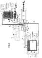
- Said first chamber 1 and second chamber 2 are substantially completely filled with a porous refractory material 11 with a high heat volume, which will be described later.
- the device comprises closed circuit circulation lines between said first chamber 1 and second chamber 2 which allow the gas contained in the installation to pass through each chamber between two opposite ends 1 1 -1 2 2 and 2 1 -2 2 , located preferably respectively at the high and low ends of said speakers.
- the circulation lines between said first and second enclosures further comprise gas compression / expansion means between the two enclosures, explained below.
- said first and second speakers are arranged vertically.
- the first enclosure 1 comprises at its upper end 1 1 an upper pipe 1 d, opening into the upper part 1 of the first chamber, and at its lower end 1 2 a first lower pipe 1 c opening in the lower part 1 b from the first speaker 1.
- the second chamber 2 comprises at its upper end 2 1 a second upper pipe 2d, opening into the upper part 2a of the second chamber 2, and at its lower end 2 2 a second lower pipe 2c opening into the lower part 2b of the second speaker 2.
- Said first and second lower conduits 1c, 2c and upper 1d, 2d, are also insulated.
- Said second chamber 2 is coupled with a first heater 5a, preferably a heater comprising an electrical resistance 5a 1 and a closed loop of heating pipe 5a 3 between two ends of the second enclosure, the gas flowing in the heating pipe 5a 3 is heated by said first heater 5a
- a first compression / expansion group 3 is interposed between said first chamber 1 and second chamber 2.
- This first compression / expansion unit 3 comprises an electric motor 3a powered by an electrical energy E 1 , enabling a first dynamic compressor 3b to be actuated. of axial or centrifugal type, and a first gas turbine 3c, itself coupled to said first compressor 3b, their respective shafts being coupled to one another as will be explained below.
- Said first compressor 3b is connected at the output to the upper end 1 1 of said first chamber 1 by said first upper pipe 1d, and said first compressor 3b is connected at its inlet to the upper end 2 1 of said second chamber 2 by said second upper pipe 2d.
- Said second upper pipe 2d is the feed pipe of the first compressor 3b and said first upper pipe 1d constituting the gas discharge pipe of the first compressor 3b after compression in storage cycle, as will be explained below.
- a second heater 5b preferably having a second electrical resistance 5a 2 , cooperates with said second upper duct 2d, said second heater 5b being interposed between the upper end 2 1 of the second enclosure 2 and the inlet of the first compressor 3b.
- Said first turbine 3c is connected to the lower end 1 2 of said first chamber 1 by said first lower pipe 1c, and said first turbine 3c is connected to the lower end 2 2 of said second chamber 2 by said second lower pipe 2c .
- Said first lower duct 1c serves to supply said first turbine 3c with gas discharged from the lower part 1b of the first enclosure 1, and the gas evacuating from said first turbine 3c joins the lower part 2b of said second enclosure 2 via said second lower channel 2c, when the device operates in storage cycle as will be explained below.
- a heat exchanger 6 cooperates with said first lower pipe 1c, between the lower end 1 2 of said first chamber 1 and said first turbine 3c.
- a second group 4 said generator group of electricity, is interposed between said first enclosure 1 and said second enclosure 2 in the following manner.
- Said second electricity generator group 4 comprises a second electric motor 4d, coupled to a second gas turbine 4c and a second compressor 4b.
- This second electric motor 4d is a small motor essentially used to launch the second turbine 4c during the start of the cycle of restitution / destocking of the energy, as will be explained below.
- the second electricity generating unit 4 comprises an electric alternator 4a, coupled to the output shaft of said second gas turbine 4c and said second compressor 4b, so as to restore an electric energy E R when said second turbine 4c and second 4b compressor are activated, as will be explained below, in a cycle of energy destocking.
- Said second turbine 4c is supplied with gas by a pipe 1d 'derived from said first upper pipe 1d (also called first upper bypass line 1d'), or a pipe parallel to said first upper pipe, ensuring the connection between the upper end 1 1 of the first chamber 1 and the second turbine 4c.
- the expanded gas leaving said second turbine 4c when the device operates in destocking cycle, is discharged to the upper end 2 1 of the second chamber 2 via a conduit 2d 'derived from the second conduit upper 2d (also called second upper bypass line 2d '), or by a pipe parallel to said second upper pipe, thus providing the connection between the upper end 2 1 of the second chamber and the second turbine 4c.
- Said second compressor 4b is supplied with gas by a branch pipe 2c 'of said second lower pipe 2c (also called second lower bypass pipe 2c') or a pipe parallel thereto, thus ensuring the connection between the lower end 2 2 the second speaker and the second compressor 4b. And, the gas is discharged from said second compressor 4b towards the lower end 1 2 of said first chamber 1, via a pipe 1c 'derived from said first lower pipe 1c (also called first lower bypass pipe 1c '), or a pipe parallel to said first lower pipe 1c, providing the connection between the lower end 1 2 and said second compressor 4b.
- a branch pipe 2c 'of said second lower pipe 2c also called second lower bypass pipe 2c'
- a pipe parallel thereto thus ensuring the connection between the lower end 2 2 the second speaker and the second compressor 4b.
- the gas is discharged from said second compressor 4b towards the lower end 1 2 of said first chamber 1, via a pipe 1c 'derived from said first lower pipe 1c (also called first lower bypass pipe 1c '),
- the second lower bypass line 2c ' provides the connection between the second compressor 4b and the second lower pipe 2c before the latter arrives at said first turbine 3c.
- the first upper bypass line 1 ensures the connection between the second turbine 4c and the first upper pipe 1d before the latter arrives at said first compressor 3b.
- the second upper bypass line 2d ' provides the junction between the second turbine 4c and the second upper pipe 2d between said second heater 5b and said first compressor 3b.
- the first lower bypass line 1c ' provides the connection between the second compressor 4b and the first lower pipe 1c between said heat exchanger 6 and said first turbine 3c.
- the enclosures 1 and 2 are filled with a porous refractory material 11, allowing the gas to flow through said speakers from one end to the other between their upper ends 1 1 -2 1 and lower 1 2 -2 2 .
- the porous refractory materials used in the first and second chambers have a porosity (void percentage) of 20 to 60%, which constitutes a good compromise between a sufficient heat exchange between the gas and the refractory materials on the one hand, and secondly, a sufficiently low pressure drop, while maintaining a sufficiently high flow rate through said porous material.
- the device according to the invention is entirely filled with neutral gas, preferably argon, namely the pipe circuits mentioned above, the turbines and compressors, the heaters, and said first and second speakers.
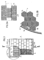
- FIG. 3 On the figure 3 is shown in section and in side view an enclosure having a sealed metal outer envelope 13, an internal insulation system 12 disposed against the wall of the outer metal casing 13 and a stack of blocks or bricks of refractory material 11 having vertical channels 11 1 in the form of perforations, preferably of circular section with a diameter of 5 to 20 mm, passing through them integrally and arranged substantially uniformly, plane by plane, over the entire horizontal section of said first enclosure, as detailed on the Figures 3A and 3B .
- the channels 11 1 of different superimposed blocks 11 are aligned with each other so as to allow the circulation of the gas in the longitudinal direction ZZ of the chamber 1, 2 between the two opposite ends of the enclosure without obstacle between the channels of different blocks arranged superimposed in the same longitudinal direction ZZ.
- a widely open support structure 14, situated in the lower part of said enclosure, makes it possible to distribute the incoming or outgoing gases through the adjoined insulated lower ducts 1c, 2c, in a substantially uniform manner over the entire section of said enclosure and to direct them and optimally, so with a minimum of losses, to the channels 11 1 vertically through said blocks of refractory materials 11 in case of supply from below.
- empty spaces 15 are provided at the top of the speakers, so as to allow good distribution of the gas when the speakers are supplied with gas from above.
- the gases arrive from the bottom and exit in the upper part of said chamber, which corresponds to the storage phase for the second chamber and the restitution phase for the first chamber, as explained below.
- the figure 3A is a partial horizontal section in plan view according to plan AA of the figure 3 .
- the blocks of refractory materials 11 are square and perforated with a plurality of parallel circular cylindrical holes in the vertical direction ZZ perpendicular to the plane of the figure.
- the refractory material blocks 11 are advantageously in direct contact with the wall of the enclosure, at the level of the insulation 12 of said enclosure, so as to limit the direct and uncontrolled passages of the hot or cold gases in this zone.
- the blocks in the successive planes of blocks of refractory materials are advantageously offset from each other by a half-module or a half-block in staggered rows, so as to ensure overall stability within said enclosure, as shown on the figure 3 .
- the blocks are stacked vertically on each other over the entire height of the enclosure, to form candles independent of each other and 5 to 10 mm apart in all directions, which allows expansion during storage-retrieval cycles, while avoiding the risk of wear at the horizontal planes AA during said storage-return cycles, when mounted in staggered rows as detailed on the figure 3 .
- Refractory blocks 11a of hexagonal section are shown near the insulating wall of a cylindrical enclosure.
- the connection with the insulating wall is done either by direct contact with the edge of a block, or by a form of insulating block 12a adapted to the curvature, or by stuffing an insulating material 12a, for example of the same type than the insulator 12 of said enclosure, or again by a form of refractory block 12b adapted to the curvature.
- said first compressor group 3 (first compressor 3b and first turbine 3c) can be operated by disconnecting said second electricity generator group 4 during a power storage cycle, or conversely, said first compressor 3 can be disconnected and opening said bypass lines to operate said second compressor 4 during an energy retrieval cycle.
- the device is shown in the energy storage or energy charging phase in the first enclosure 1.
- the complete installation is at ambient temperature T0 of 10 to 20 ° C, the gas contained in the enclosures and pipes therefore being at this ambient temperature T0 and the two enclosures are at the same initial pressure related to the pressure of loading, for example from 1 to 1.2 bara (absolute bar).
- the mass of refractory materials is then heated inside the second chamber 2 to a temperature T2 of 600 ° C.
- the gas is circulated in the closed loop of the second chamber between its upper ends 2 1 and lower 2 2 that is heated outside the chamber with the first heater 5a, which heats the gas inside the heating pipe 5a 3 ensuring the loop between the lower ends 2 2 and upper 2 1 of the second enclosure outside thereof.
- the gas is circulated in the heating pipe 5a 3 through a fan 5a 5 and the first heater 5a comprises a first resistor 5a 1 .
- a valve 5a 4 isolates the first heater 5a when it is out of service at the end of the initial preheating, thus avoiding unwanted transfers and recirculation of gas in a normal cycle.
- the valve 5a 4 is closed and the gas is sent via the second upper pipe 2d in the first compressor 3b , so as to heat it to the temperature T1 of 1200 to 1400 ° C, for example 1300 ° C output of said first compressor.
- a pressure gradient is established between the two chambers, the first chamber being raised to the pressure P1 of 2 to 4 baras (absolute bar, 2.10 5 to 4.10 5 Pa) and the pressure P2 in the second chamber being reduced to about 1 bara (1.10 5 Pa).
- the upper part 1a of refractory material tends to the temperature T1 of 1300 ° C while the lower part 1b is established at a temperature T'1 of 20 to 100 ° C.
- the gas At the outlet at the lower end 1 2 of the first chamber, the gas must be expanded by the first turbine 3c to be restored to the pressure P2 of the second chamber before being reintroduced into the second chamber, expanded and cooled to a minimum. temperature T3 at the bottom of the second enclosure.
- T3 at the bottom of the second enclosure.
- the upper part 1a of refractory materials of the first hot chamber at the temperature T1 of 1300 ° C occupies a larger and larger volume of l enclosure, that is to say that the hot gas introduced at the upper end 1 1 of the first chamber 1 gives its calories to said refractory materials and heats an increasingly large volume of refractory material of the first chamber.
- a front 1e which corresponds in fact to a temperature transition zone is shown schematically by a line on the figures 1 and 2 .
- the lower part 2b of the second chamber at the temperature T3 of at least -80 to -20 ° C occupies a larger and larger volume of the chamber 2.
- the front 2e schematizing a line of separation which is in makes a transition zone between the lower part 2b at the temperature T3 and an upper part 2a at the temperature T2, moves progressively upwards as the different cycles of circulation of the gas progress.
- the first compressor 3b is powered by an electric motor 3a which consumes electrical energy E 1 .
- the first turbine 3c is coupled to the first compressor 3b to the shaft from which it is coupled, so that the first turbine 3c supplies energy to the first compressor 3b in addition to the energy supplied by the first motor 3a.
- the temperature of the upper part 2a of the second chamber has tendency to decrease at a temperature T'2 less than T2, that is to say below 600 ° C for example, from 300 to 450 ° C.
- the gas leaving the upper end 2 1 of the second chamber is advantageously heated by means of a second heater 5b comprising a second resistor 5a 2 enabling heating the gas flowing in the upper pipe 2d to maintain it at a temperature T2 of 600 ° C before it arrives in the first compressor 3b.
- the engine 3a is set so as to maintain the outlet temperature of the first compressor 3b at constant temperature T1 of the order of 1300 ° C.
- the temperature of the gas entering the second heater 5b is measured and the quantity of electric energy E 2 injected per second is adjusted in real time in the second heater 5b to bring the gas at substantially constant temperature T2.
- the power injected into the installation during these storage cycles will therefore correspond to the electrical energy E 1 supplying the first electric motor 3a, supplemented with electrical energy E 2 supplying the second heater 5b.
- the heat exchanger 6 is supplied with a cooling fluid such as water or cold air at 10-20 ° C to cool the gas leaving the the first chamber at the temperature T'1 from 20 to 100 ° C and bring it to the temperature T0 of 10 to 20 ° C.
- the cooling fluid of the exchanger 6 leaves the exchanger 6 at 6d at a temperature of 50 to 100 ° C depending on the flow of air or cooling water.
- the heat exchanger 6 thus releases a thermal energy E 3 in the form of water heated to 50-100 ° C.
- This thermal energy E 3 is energy that can not be stored in the system, but can be recovered either in a heat pump or used in industrial processes or for of urban heating. E 3 therefore constitutes, during a complete storage cycle, a loss which affects the overall efficiency of the device.
- a lower part 1b is maintained in the first enclosure representing 10 to 20% of the total volume of the enclosure which remains at the temperature T'1 of 20 to 100 ° C.
- an upper part 2a of the second chamber is maintained at the temperature T2 or close to the temperature T2, that is to say that the storage is interrupted when the lower part 2b of the second chamber at the temperature of -80 to -20 ° C represents 80 to 90% of the volume of the second chamber.
- This volume of 10 to 20% corresponds in fact to the volume of the thermal transition layer of height described later with reference to figures 7 .
- the energy restitution cycle stored in the first chamber 1 is represented in the form of electric energy E R.
- the various valves V 1 to V 4 are actuated to supply the second group 4 with the said first pipe and the second upper branch of branching 1d ', 2d' and first and second lower bypass lines 1c ', 2c', the first compressor 3b and first turbine 3c no longer being supplied with gas.
- a small electric motor 4d is actuated which actuates the second turbine 4c and the second compressor 4b coupled thereto, so that establish a pressure gradient between the two enclosures 1 and 2 respectively with a pressure P'1 greater than P1 in the first chamber 1 and a temperature P'2 less than P2 in the second chamber 2.
- the second compressor sucks gas from the second chamber and sends it into the first chamber, which increases the pressure in said first chamber, thereby supplying gas to the second turbine, to finally return to the second enclosure and continue its circulation cycle.
- the turbine reaches its own speed, we stop feeding the small electric motor 4d.
- the second turbine 4c draws gas from the upper part of the first chamber to the second chamber by performing cooling and expansion of the gas.
- the losses at the turbine and compressor are such that P'1 / P'2> P1 / P2.
- P'1 is from 3 to 5 baras and P'2 from 1 to 1.5 baras.
- the motor 4d When the pressure gradient P'1 / P'2 is established, the motor 4d is cut.
- the gas in the lower part 2b of the second chamber is at the temperature T3 of -80 to -20 ° C. which was its temperature at the end of the storage cycle. And the gas is conveyed towards the second compressor 4b to be recompressed at the pressure P'1. It is concomitantly heated to the temperature T4, which temperature T4, because of the losses of the second compressor is greater than the temperature T0.
- T4 is of the order of 100-150 ° C.
- the gas at the temperature T4 greater than T0 at the outlet of the second compressor 4b must therefore be cooled to the temperature T'1 using the exchanger 6 before being sent to the lower end 1 2 of the first chamber 1, the lower part 1b is at the T'1 temperature of 20 to 120 ° C.
- the cooling of the gas output of the second compressor 4b during the destocking cycle has the effect that thermal energy E4 is lost by heating the coolant.
- this cooling of the gas from the temperature T4 to T'1 facilitates, during the energy storage cycles, the cooling of the gas at the outlet of the lower end 1 1 of the first chamber of the temperature T'1 up to the temperature T0 downstream of the heat exchanger so that the gas reaches room temperature T0, entering the first turbine 3c during energy storage cycles.
- the loss of thermal energy E4 during retrieval cycles is offset by a loss of thermal energy E3 at the level of the exchanger 6 less important during storage cycles.
- the thermal energies E3 + E4 correspond globally to the losses of the installation related to the T4-T0 gradient and due to the losses in the compressors and turbines.
- E R The energy restored by the system E R corresponds to the energy released by the second turbine 4c which actuates an electric generator-alternator 4a which makes it possible to restore energy in the form of electricity.
- E R more precisely corresponds to the energy released by the second turbine 4c less the energy consumed by the second compressor 4b coupled thereto.
- E R E 1 + E 2 - (E 3 + E 4 ) -E 5 .
- E 5 representing losses through insulation of enclosures, pipes, turbines and compressors and various accessories.
- the losses E3 + E4 + E5 represent 15 to 25% with respect to the energies E 1 + E 2 provided, the overall efficiency of the installation and the method of restitution of energy being thus from 75 to 85%.
- the destocking is stopped before the first chamber is completely cooled and the second chamber is completely reheated in order to maintain a thermal transition layer in the upper part.
- This thermal transition layer in the upper part 2b of the second temperature chamber T2 facilitates the restoration of the pressure gradient between the two speakers P'1 / P'2 at the beginning of the energy recovery cycle corresponding to the same temperatures T1 / T2 respectively in the first / second speakers.
- Maintaining a thermal transition layer at one end of the first and second enclosures at the end of the storage cycle and at the end of the rendering cycle is also advantageous in terms of overall energy efficiency of the installation. Indeed, if it was desired to fully heat the first chamber at the end of the storage cycle, the gas leaving the lower end 11 of the first chamber during the heating of the volume corresponding to the thermal transition layer at the end lower of the first enclosure, would come out at a temperature above the temperature T'1, which would imply a higher cooling energy E3 and therefore higher energy losses.
- maintaining a lower part 1b at the temperature T'1 at the end of storage and an upper part 2a at the temperature T2 in the second chamber at the end of storage facilitates the start of the restitution cycle, which requires a 4d motor for a shorter time to establish a stable operation with the temperature gradients T1 and T2 in the first and second speakers respectively at pressures P'1 and P'2 during the restitution.
- the maintenance of a hot top layer 1a at temperature T1 in the first chamber at the end of restitution and the maintenance of a cold bottom layer 2b at the temperature T3 at the end of the restitution cycle facilitates the start of the cycle. subsequent storage, decreasing the electrical energy E2 necessary to maintain the gas entering the first compressor 3b at the temperature T2.
- the sizing of the first compressor 3b / first turbine 3c implemented during the storage cycles, and second compressor 4b / second turbine 4c during retrieval cycles, are radically different given the different temperatures to which they are subjected. Indeed, the volume of a gas increasing with its temperature, the compressor and turbine operating with gases entering at high temperature will have to be larger. Therefore, during the storage phase, the first compressor 3b is a large compressor since it operates at a temperature T1 of 1300 ° C, while the first turbine 3c which operates at a temperature T3 of about -50 ° C will be a small turbine.
- the second compressor 4c which operates at T3 temperature of -50 ° C will be a small compressor while the second turbine 4c operating at T1 temperature of about 1300 ° C will be a large turbine.
- the implementation of a first small turbine 3c during the storage phase facilitates its driving by the first large compressor 3b.
- the implementation of a small second compressor 4b reduces energy losses and the energy E R corresponds to the energy released by the second turbine 4c less the energy consumed by the second compressor 4b.
- T3 the lowest possible input of the second compressor 4b to also reduce energy consumption affecting the overall energy efficiency of the system.
- the front 1e separating the cold lower part 1b to T'1 and the upper part 1a hot to T1 of the first chamber become moves progressively upwards, while the front 2nd separating the upper hot part 2a at temperature T2 from the cold lower part 2b to temperature T3 of the second chamber moves progressively downwards.
- the commissioning of the exchanger 6 on the gas return circuit between the second compressor 4b and the lower part of the first enclosure 1, on the one hand, and secondly, the operation of the second turbine 4c are adjusted so as to maintain said temperatures T1 and T2 at constant values respectively, for example of 1300 ° C. and 500 ° C., throughout the energy restitution cycle.
- the temperatures T1 and T2 are constant and identical on the cycles of loading / storage and unloading / energy release.
- thermodynamic cycles corresponding respectively to the energy storage and restitution cycles, the installations and processes of which are described in connection with the figures 1 and 2 .
- These thermodynamic cycles correspond to a unit volume of gas, for example 1 m 3 , performing a complete cycle during which it acquires energy in an enclosure or a compressor, then restores it in a turbine, or the other enclosure.
- Said unit volume carries out this thermodynamic cycle in a very short time compared to the complete duration of a storage or restitution cycle, and thus performs hundreds or thousands, even tens of thousands of thermodynamic cycles, that is, that is to say, it goes back so many times in the compressor, the turbine, the pipes and each of the speakers.
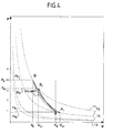
- the figure 5 illustrates the storage phase described in the figure 1 .
- the gas coming from the upper part of the second chamber enters the first compressor 3b at the temperature T2 at point A. It is compressed and comes out at temperature T1 at point B. It penetrates the mass of refractory 11 of the first enclosure 1, passes through the mass of refractory giving up its calories, which causes a gradual descent of the temperature front down.
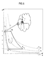
- thermodynamic cycle of energy restitution detailed on the figure 6 unfolds as follows.
- the high temperature gas T1 leaves the first enclosure 1 from above, which corresponds to point B of the diagram.
- the gas is then turbinated at 4c where it returns the energy to the electric generator (ER) and is found at point A of the diagram at the temperature T2.
- ER electric generator
- the gas then passes into the second compressor 4b and exits at a temperature T4 greater than the desired temperature T0: it then passes into the heat exchanger 6 where it restores the energy quota E4 to the outside, to end up at the temperature T0, therefore at point C of said diagram. Finally, it enters from the bottom into the first chamber where it recovers energy and heats up to reach the point B of the diagram, which causes a gradual rise of the temperature front 1 e upwards, so a global cooling of said first enclosure.
- the turbo-machines In order to remain within the operating ranges of the turbo-machines corresponding to their best efficiency, advantageously one does not charge completely, or completely discharge the first speaker, which corresponds, as detailed on the Figure 7B , to limit the charge / discharge cycle to the maximum height ⁇ H 1 , corresponding for example to 80-90% of the total height, therefore the total heat capacity of said first chamber.
- this transition zone also exists in the second chamber but it corresponds to different temperatures, for example -50 ° C in the lower part, and 500 ° C in the upper part.
- the percentage of the heat mass used then corresponds to a height ⁇ H 2 , said percentage used being preferably substantially identical to that of said first chamber, that is to say 80-90%.
- a second reason lies in the equality of temperatures T1 and T2 during the 2 storage / recovery phases, obtained by using different turbine-compressor assemblies working with different pressure ratios (P1 / P2 and P'1 / P'2 ).
- a third reason for the overall good efficiency comes from the fact that during the storage phase the losses of the hot compressor 3b are extracted as heat in the gas. This energy is stored in the refractory of the first chamber 1 as well as the heat pumped from the second chamber. This loss of energy from the hot compressor is largely recovered as useful work during the restitution phase.
- the fourth reason is the use of regenerators to exchange heat with the gas. It is indeed possible to develop sets of refractory parts capable of operating at a very high temperature and having a very large exchange surface between the gas and the solids. This makes it possible to approach as well as possible the equality of the temperatures T1 and T2 during the 2 phases.
- the storage capacity is related to the mass of refractory.
- the arrangement according to the invention has the advantage that almost all of the refractory mass is used to play a dual role: storage of heat and heat exchange with the gas.
- T1 the temperature of the gas at the inlet and T2 that at the outlet.
- T2 ⁇ T1 and W is then negative (power extracted from the gas).
- W is positive (power supplied to the gas).
- the density of the gas is proportional to the molar mass of the gas. However, it is easier to compress or relax a heavy gas than a light gas. The necessary machines are smaller and more economical with heavy gas than with light gas.
- the molar mass is respectively 40 for argon, 44 for CO2, 84 for krypton, 131 for xenon and 222 for radon.
- a mono-atomic gas such as helium, neon, argon or other rare gases of higher molar mass.
- the diatomic gases such as nitrogen and tri-atomic such as air or CO2 are very abundant and cheap, but at high temperature, are aggressive towards the metals constituting the envelope of the speakers, the pipes or the blades of the turbines and compressors, it is therefore advantageously used as gas in the device a neutral gas totally inert vis-à-vis the metal elements of the device, such as helium, neon, argon or other rare gases of higher molar mass.
- helium, neon and argon are present in ambient air in significant percentages and are available in large quantities at acceptable costs.
- argon is the most efficient gas for use in the device according to the invention, because it is monoatomic, it is inert at high and very high temperature vis-à-vis elements metallic component of the device according to the invention and it has a high molar mass and a low acquisition cost.
- Said first refractory material of the first enclosure is, for example, chamotte, also called second clay ("fire clay") capable of withstanding 1200 ° C or a product with a high content of alumina and / or magnesia.
- the second refractory material in the second enclosure may be first fired clay.
- the refractory materials 11 are in the form of perforated bricks by parallel channels 5 to 20 mm in diameter and through-through, and arranged to allow the circulation and passage of gas through the channels in the longitudinal direction of the enclosure.
- the chamotte remains the most economical of all these products, but its maximum temperature remains very much lower than that of the others.
- E V. Cp. (T - T0) in which E is expressed in joules, V is the heated refractory volume, Cp the heat capacity in J / m3 / K, T the heating temperature and T0 the initial temperature before heating.
- Centrifugal or axial turbines and compressors are generally limited in temperature due to the aggressiveness of the gases resulting from the combustion, but in the device according to the invention, said turbines and said compressors are operated in a closed circuit with a neutral gas. such as argon, which allows for these machines operating points at a much higher temperature than in the prior art.
- a neutral gas such as argon
- the energy stored in the first and second speakers is not lost except in case of prolonged inactivity of the device in loading and unloading, the losses then taking place to the outside environment, mainly through the insulation 12 of said speakers.
- thermal insulation is made with materials having a high porosity, such as ceramic fiber felt or ceramic foams. Calculations show that for the example cited above insulation 2m thick with conventional fibrous materials can limit the loss of energy to less than 1% per day.
- the large compressor 3b and the large turbine 4c that work at high temperature can advantageously be made with carbon-based materials.
- This body is mechanically resistant to very high temperatures, up to more than 2000 ° C. It is not usually used to build turbomachines because it oxidizes rapidly in oxidizing gases, such as air or products resulting from combustion. This limitation does not intervene here which allows to consider its use.
- Carbon turbines have already been carried out experimentally, or for rocket engines whose life is only a few minutes. In this application according to the invention, such turbines or compressors would have no limitation of life. In current machines made with metallic materials, it is necessary to cool the blades by an internal circulation of cold gas which is at the expense of efficiency. Despite this, mobile blades have a limited life due to the phenomenon of creep.
Landscapes
- Engineering & Computer Science (AREA)
- Chemical & Material Sciences (AREA)
- Combustion & Propulsion (AREA)
- Mechanical Engineering (AREA)
- General Engineering & Computer Science (AREA)
- Engine Equipment That Uses Special Cycles (AREA)
- Filling Or Discharging Of Gas Storage Vessels (AREA)
- Waste-Gas Treatment And Other Accessory Devices For Furnaces (AREA)
Claims (29)
- Anlage zur Speicherung und Wiedergewinnung von elektrischer Energie, dadurch gekennzeichnet, daß sie umfaßt:- zwei Räume, einen ersten und einen zweiten (1, 2), die ein Gas sowie ein erstes und ein zweites poröses feuerfestes Material (11) enthalten, welche geeignet sind, durch Kontakt zwischen den porösen feuerfesten Materialien und einem durch die Räume zirkulierenden Gas Wärme zu übertragen, und- einen geschlossenen Kreis aus Rohrleitungen (1c, 1c', 2c, 2c', 1 d, 1d', 2d, 2d'), der das Zirkulieren eines Gases, das nacheinander einen jeden der beiden Räume von einem Ende zum anderen durchströmt, ermöglicht, sowie- Mittel zum Komprimieren (3b, 4b) und Mittel zum Entspannen (3c, 4c) des Gases, das in den Rohrleitungen zwischen jedem der Enden eines Raums, das mit einem Ende des anderen Raums verbunden ist, zirkuliert, und- vorzugsweise erste Gaserhitzungsmittel, die geeignet sind, das in dem zweiten Raum (5a) zirkulierende Gas zu erhitzen, und- weiterhin vorzugsweise Mittel zum Abkühlen (6) von Gas, das zwischen einem der Enden des ersten Raums und Kompressionsmitteln (4b) und Entspannungsmitteln (3c) zirkuliert, die geeignet sind, an diesem Ende aus dem ersten Raum austretendes Gas zu kühlen, bevor es in den Entspannungsmitteln (3c) entspannt wird bzw. in den ersten Raum eintretendes Gas zu kühlen, nachdem es durch die Kompressionsmittel (4b) komprimiert worden ist.
- Anlage zur Speicherung und Wiedergewinnung von Energie nach Anspruch 1, dadurch gekennzeichnet, daß sie umfaßt:- A) einen mit einem ersten porösen feuerfesten Material gefüllten wärmeisolierten ersten Raum (1), der geeignet ist, von einem Gas durchströmt zu werden, das durch den ersten Raum zwischen 2 Enden, einem oberen und einem unteren (11, 12) des ersten Raums zirkuliert,- B) einen mit einem zweiten porösen feuerfesten Material gefüllten wärmeisolierten zweiten Raum (2), der geeignet ist, von einem Gas durchströmt zu werden, das durch den zweiten Raum zwischen 2 Enden, einem oberen und einem unteren (21, 22) des zweiten Raums zirkuliert, und- C) wärmeisolierte Rohrleitungen (1c, 1c', 2c, 2c', 1 d, 1d', 2d, 2d'), die das Zirkulieren von Gas im geschlossenen Kreislauf zwischen den 2 Räumen ermöglichen, umfassend erste und zweite obere Rohrleitungen (1d-1d', 2d-2d') zwischen den oberen Enden (11, 21) der beiden Räume sowie erste und zweite untere Rohrleitungen (1c-1c', 2c-2c') zwischen den unteren Enden (12, 22) der beiden Räume, und- D) vorzugsweise erste Gaserhitzungsmittel (5a), die geeignet sind, Gas innerhalb des zweiten Raums zu erhitzen, und- E) erste Gaskompressionsmittel (3), die einen ersten Elektromotor (3a) umfassen, welcher geeignet ist, mit einer zu speichernden elektrischen Energie (E1) gespeist zu werden, um einen ersten Verdichter (3b) anzutreiben, der geeignet ist, ein über eine zweite obere Rohrleitung (2d) aus dem oberen Ende (21) des zweiten Raums kommendes Gas zu komprimieren, um es über eine erste obere Rohrleitung (1 d) zu dem oberen Ende (11) des ersten Raums zu leiten, und- F) erste Gasentspannungsmittel (3c), die eine erste Turbine (3c) umfassen, welche geeignet ist, das über eine erste untere Rohrleitung (1c) von dem unteren Ende (12) des ersten Raums kommende Gas zu entspannen, um es über eine zweite untere Rohrleitung (2c) zu dem unteren Ende (22) des zweiten Raums zu leiten,
und- G) zweite Gaskompressionsmittel (4b), die geeignet sind, das über eine weitere zweite untere Rohrleitung (2c, 2c') von dem unteren Ende (22) des zweiten Raums kommende Gas zu komprimieren, um es über eine weitere erste untere Rohrleitung (1c, 1c') zu dem unteren Ende (12) des ersten Raums zu leiten, und- H) zweite Gasentspannungsmittel, die eine zweite Turbine (4c) umfassen, welche geeignet ist, das über eine weitere erste obere Rohrleitung (1d, 1d') von dem oberen Ende (11) des ersten Raums kommende Gas zu entspannen, um es über eine weitere zweite obere Rohrleitung (2d, 2d') zu dem oberen Ende (21) des zweiten Raums zu leiten, wobei die zweiten Entspannungsmittel geeignet sind, einen elektrischen Generator (4a) anzutreiben, der geeignet ist, elektrische Energie (ER) wiederzugewinnen, und- I) Gasabkühlmittel, vorzugsweise einen Wärmetauscher (6), die geeignet sind, Gas, welches in ersten unteren Rohrleitungen (1c, 1c') zwischen einerseits dem unteren Ende (12) des ersten Raums und andererseits den Aus- und Eingängen des zweiten Verdichters (4b) bzw. der ersten Turbine (3c) zirkuliert, zu kühlen. - Anlage zur Speicherung und Wiedergewinnung von elektrischer Energie nach Anspruch 2, dadurch gekennzeichnet, daß sie zweite Gaserhitzungsmittel (5b) umfaßt, die geeignet sind, das in einer zweiten oberen Rohrleitung (2d) zwischen dem oberen Ende des zweiten Raums und dem ersten Verdichter (3b) zirkulierende Gas zu erhitzen.
- Anlage zur Speicherung und Wiedergewinnung von elektrischer Energie nach Anspruch 2 oder 3, dadurch gekennzeichnet, daß die erste Turbine (3c) geeignet ist, über den ersten Verdichter (3b), mit dem sie mechanisch gekoppelt ist, angetrieben zu werden.
- Anlage zur Speicherung und Wiedergewinnung von elektrischer Energie nach einem der Ansprüche 2 bis 4, dadurch gekennzeichnet, daß die zweite Turbine (4c) mit einem Hilfselektromotor (4d) gekoppelt ist, der geeignet ist, sie anzutreiben.
- Anlage zur Speicherung und Wiedergewinnung von elektrischer Energie nach einem der Ansprüche 2 bis 5, dadurch gekennzeichnet, daß der zweite Verdichter (4b) über die zweite Turbine (4c), mit der er mechanisch gekoppelt ist, angetrieben wird.
- Anlage zur Speicherung und Wiedergewinnung von elektrischer Energie nach einem der Ansprüche 1 bis 6, dadurch gekennzeichnet, daß sie mit einem Neutralgas, vorzugsweise Argon gefüllt ist.
- Anlage zur Speicherung und Wiedergewinnung von elektrischer Energie nach einem der Ansprüche 2 bis 7, dadurch gekennzeichnet, daß der erste Raum und das erste poröse feuerfeste Material in der Lage sind, einer Temperatur T1 von wenigstens 750 °C, vorzugsweise von wenigstens 750 bis 2000 °C, weiterhin vorzugsweise von 1000 bis 1500 °C standzuhalten und die zweite Turbine dazu ausgelegt ist, ein Gas auf die Temperatur T1 zu entspannen, während die erste Turbine mit einer geringeren Kapazität als die zweite Turbine dazu ausgelegt ist, ein Gas von der Umgebungstemperatur T0 auf eine Temperatur T3 von -80 bis -20 °C zu entspannen.
- Anlage zur Speicherung und Wiedergewinnung von elektrischer Energie nach einem der Ansprüche 2 bis 8, dadurch gekennzeichnet, daß der zweite Raum und das zweite poröse feuerfeste Material in der Lage sind, einer Temperatur T2 von wenigstens 400 °C, vorzugsweise von wenigstens 400 °C bis 1000 °C, weiterhin vorzugsweise von 500 bis 700 °C standzuhalten und der erste Verdichter dazu ausgelegt ist, ein Gas auf die Temperatur T2 zu komprimieren, während der zweite Verdichter mit einer geringeren Kapazität als der erste Verdichter dazu ausgelegt ist, ein Gas von der Temperatur T3 von -80 bis -20 °C auf die Umgebungstemperatur zu komprimieren.
- Anlage zur Speicherung und Wiedergewinnung von elektrischer Energie nach einem der Ansprüche 2 bis 9, dadurch gekennzeichnet, daß der erste Verdichter geeignet ist, einen größeren Volumenstrom als die erste Turbine bereitzustellen, und die zweite Turbine geeignet ist, einen größeren Volumenstrom als der zweite Verdichter bereitzustellen, und der erste Verdichter und die zweite Turbine aus Kohlenstoff ausgebildet sind.
- Anlage zur Speicherung und Wiedergewinnung von elektrischer Energie nach einem der Ansprüche 1 bis 10, dadurch gekennzeichnet, daß das erste und das zweite poröse feuerfeste Material eine Porosität von 20 bis 60 % aufweisen.
- Anlage zur Speicherung und Wiedergewinnung von elektrischer Energie nach Anspruch 11, dadurch gekennzeichnet, daß das erste und das zweite poröse feuerfeste Material von aneinander gefügten porösen Ziegeln (11) gebildet sind, die vorzugsweise von zylindrischen Löchern (111) durchzogen sind, welche in einer gleicher Längsrichtung wie der Raum, in dem sie zusammengefügt sind, parallel angeordnet sind, wobei die Löcher weiterhin vorzugsweise einen Durchmesser von 5 bis 20 mm aufweisen.
- Anlage zur Speicherung und Wiedergewinnung von elektrischer Energie nach einem der Ansprüche 1 bis 12, dadurch gekennzeichnet, daß das erste und das zweite poröse feuerfeste Material von gebranntem Ton mit hohen Gehalten an Verbindungen, welche aus Magnesiumoxid, Aluminiumoxid und Kalk ausgewählt sind, gebildet sind.
- Anlage zur Speicherung und Wiedergewinnung von elektrischer Energie nach einem der Ansprüche 1 bis 13, dadurch gekennzeichnet, daß das erste poröse feuerfeste Material von Ton aus zweitem Brennvorgang oder Schamotte gebildet ist.
- Anlage zur Speicherung und Wiedergewinnung von elektrischer Energie nach einem der Ansprüche 1 bis 14, dadurch gekennzeichnet, daß das zweite poröse feuerfeste Material von Ton aus erstem Brennvorgang gebildet ist.
- Anlage zur Speicherung und Wiedergewinnung von elektrischer Energie nach einem der Ansprüche 1 bis 15, dadurch gekennzeichnet, daß der erste und der zweite Raum jeweils ein Volumen von wenigstens 5000 m3, vorzugsweise von 10.000 bis 45.000 m3 aufweisen.
- Verfahren zur Speicherung von elektrischer Energie (E1) in Form von Wärmeenergie, wobei eine Anlage nach einem der Ansprüche 1 bis 16 verwendet wird, dadurch gekennzeichnet, daß nach einem Anfangsschritt des Vorheizens des Gases des zweiten Raums, das auf eine Temperatur T2 erhitzt wird, wobei die Anlage mit einem anfangs auf Umgebungstemperatur T0 befindlichen Permanentgas gefüllt ist, die aufeinanderfolgenden Schritte durchgeführt werden, bei denen:1) das aus dem oberen Ende (21) des zweiten Raums (2) mit einer Temperatur T2 austretende Gas durch Komprimieren in einem ersten Verdichter (3b) auf eine oberhalb einer Temperatur T2 liegende Temperatur T1 erhitzt wird, bevor es zu dem oberen Ende (11) des ersten Raums geleitet wird, in dem sich ein Druck P1, welcher höher als der Druck P2 des zweiten Raums ist, einstellt, wobei der erste Verdichter (3b) durch einen mit der zu speichernden elektrischen Energie (E1) gespeisten ersten Elektromotor (3a) angetrieben wird, und2) das Gas den ersten Raum zwischen dem oberen Ende (11) und seinem unteren Ende (12) vollständig durchquert und es aus dem unteren Ende (12) des ersten Raums mit einer Umgebungstemperatur T0 oder einer Temperatur T'1, die oberhalb von T0, aber unterhalb von T2 liegt, wieder austritt, und3) das Gas anschließend mit Hilfe von Gasabkühlmitteln (6), vorzugsweise vom Typ Wärmetauscher, nach dem Ausgang des unteren Endes (12) des ersten Raums gegebenenfalls auf eine Umgebungstemperatur T0 abgekühlt wird, und4) das Gas dann durch eine erste Turbine (3c), die vorzugsweise durch den ersten Verdichter (3b) angetrieben wird, auf den Druck P2 des zweiten Raums, welcher geringer als der Druck P1 ist, entspannt wird, wodurch das Gas auf eine Temperatur T3 unterhalb von T0 abgekühlt ist, bevor es in den zweiten Raum über dessen unteres Ende (22) eintritt, und5) man das Gas zwischen dem unteren Ende (22) und dem oberen Ende (21) des zweiten Raums durch den zweiten Raum zirkulieren läßt, was bewirkt, daß das Volumen des feuerfesten Materials des auf die Temperatur T3 gekühlten unteren Teils (2b) des zweiten Raums vergrößert wird und daß das seines oberen Teils (2a) mit der Temperatur T2 oder T'2, welche unterhalb von T2, aber oberhalb von T0 und T'1 liegt, verringert wird, und, falls erforderlich, das aus dem zweiten Raum mit der Temperatur T'2 austretende Gas mit Hilfe von zweiten Gaserhitzungsmitteln (5b) auf die Temperatur T2 erhitzt wird, und6) die obigen Schritte 1) bis 5) wiederholt werden, bis der auf die Temperatur T1 erhitzte obere Teil (1a) des ersten Raums wenigstens 80 % des Volumens des ersten Raums einnimmt und bis der auf die Temperatur T3 abgekühlte untere Teil (2b) des zweiten Raums wenigstens 80 % des Volumens des zweiten Raums einnimmt.
- Verfahren nach Anspruch 17, dadurch gekennzeichnet, daß bei Schritt 6) die Speicherung unterbrochen wird, so daß der untere Teil (1b) des ersten Raums mit der Temperatur T'1 wenigstens 10 % des Volumens des ersten Raums, vorzugsweise 10 bis 20 % des Volumens des ersten Raums ausmacht, und/oder der obere Teil (2a) des zweiten Raums mit der Temperatur T2 weniger als 20 %, vorzugsweise 10 bis 20 % des Volumens des zweiten Raums ausmacht.
- Verfahren nach einem der Ansprüche 17 oder 18, dadurch gekennzeichnet, daß die Temperaturen T1 und T2 derart sind, daß T1/T2 = 1,5 zu 3 und T1/T0 größer als 2, vorzugsweise größer als 3 und weiterhin vorzugsweise kleiner als 6 ist und P1/P2 2 zu 4 beträgt.
- Verfahren nach einem der Ansprüche 17 bis 19, dadurch gekennzeichnet, daß T1 750 °C bis 2000 °C, vorzugsweise 1000 bis 1500 °C beträgt und T2 400 bis 1000 °C, vorzugsweise 500 bis 700 °C beträgt.
- Verfahren nach Anspruch 19 oder 20, dadurch gekennzeichnet, daß der Druck P1 2 bis 4 bar absolut (2.105 bis 4.105 Pa) beträgt und P2 0,5 bis 1,5 bar absolut (0,5.105 bis 1,5.105 Pa) beträgt.
- Verfahren nach einem der Ansprüche 17 bis 21, dadurch gekennzeichnet, daß T0 10 ° bis 50 °C und T3 -80 °C bis -20 °C beträgt, wobei T'1 gegebenenfalls 20 ° bis 150 °C beträgt.
- Verfahren nach einem der Ansprüche 17 bis 21, dadurch gekennzeichnet, daß eine Menge an elektrischer Energie von 20 MW-hr bis 10.000 MW-hr gespeichert wird.
- Verfahren zur Wiedergewinnung einer elektrischen Energie (ER) aus einer mittels eines Verfahrens nach einem der Ansprüche 17 bis 23 gespeicherten Wärmeenergie, dadurch gekennzeichnet, daß nach einer anfänglichen Startphase, in der der zweite Verdichter (4b) und die zweite Turbine (4c) mit dem Hilfselektromotor (4d) angetrieben werden, wobei während der Anfangsphase ein Druckgradient zwischen dem Druck P'1 des ersten Raums und einem Druck P'2 kleiner als P'1 des zweiten Raums aufgebaut wird, welcher derart ist, daß P'1 größer ist als P'2, wobei vorzugsweise P'1 größer ist als P1 und P'2 kleiner ist als P2, die aufeinanderfolgenden Schritte durchgeführt werden, bei denen:1) das über das obere Ende (11) des ersten Raums (1) mit der Temperatur T1 austretende Gas durch die zweite Turbine (4c) entspannt und auf die Temperatur T2 abgekühlt wird, und die zweite Turbine (4c) einen Stromgenerator (4a) antreibt, der ermöglicht, eine zurückgewonnene elektrische Energie (ER) bereitzustellen, und2) das Gas den zweiten Raum von seinem oberen Ende (21) bis zu seinem unteren Ende (22) durchströmt, wobei ein oberer Teil (2a) des zweiten Raums auf die Temperatur T2 erhitzt wird, wobei ein unterer Teil (2b) des zweiten Raums auf der Temperatur T3 bleibt, und3) das Gas, welches aus dem unteren Ende (22) des zweiten Raums, an seinem unteren Ende (22) mit der Temperatur T3 austritt, anschließend durch Durchlaufen des zweiten Verdichters (4b), der vorzugsweise durch die über die zweite Turbine (4c) freigesetzte Energie angetrieben wird, komprimiert wird, um es auf eine Temperatur T4 oberhalb einer Umgebungstemperatur T0 und gegebenenfalls oberhalb von T'1, aber unterhalb von T2 am Ausgang des zweiten Verdichters (4b) zu erhitzen, und4) vorzugsweise das Gas dann mit Hilfe von Kühlmitteln (6) auf die Umgebungstemperatur T0 oder T'1 abgekühlt wird, bevor es in den ersten Raum (1) über sein unteres Ende (12) eingeleitet wird, um wieder in den unteren Teil (1b) des ersten Raums, der sich auf der Temperatur T'1 befindet, zu gelangen, und5) man das Gas durch den ersten Raum zirkulieren läßt, was bewirkt, daß das Volumen des feuerfesten Materials des unteren Teils (1b) mit der Temperatur T'1 vergrößert wird und daß das Volumen des feuerfesten Materials des oberen Teils (1a) mit der heißen Temperatur T1 verringert wird, und6) die obigen Schritte 1) bis 5) wiederholt werden, bis der untere Teil (1b) des ersten Raums mit der Temperatur T1 wenigstens 80 % des Volumens des ersten Raums ausmacht und bis der obere Teil (2a) des zweiten Raums mit der Temperatur T2 wenigstens 80 Vol.-% des zweiten Raums ausmacht.
- Verfahren nach Anspruch 24, dadurch gekennzeichnet, daß bei Schritt 6) das Energiewiedergewinnungsverfahren unterbrochen wird, so daß ein oberer Teil (1a) des ersten Raums auf einer Temperatur T1 gehalten wird, wobei der obere Teil (1a) weniger als 20 Vol.-%, vorzugsweise 10 bis 20 Vol.-%, des ersten Raums ausmacht, und/oder ein unterer Teil (2b) des zweiten Raums mit der kalten Temperatur T3 weniger als 20 %, vorzugsweise 10 bis 20 % des Volumens des zweiten Raums ausmacht.
- Verfahren nach einem der Ansprüche 24 oder 25, dadurch gekennzeichnet, daß der Wirkungsgrad der Wiedergewinnung von elektrischer Energie durch den Stromgenerator (4a) ER/E1 über 60 % liegt, vorzugsweise 75 bis 85% beträgt.
- Verfahren nach einem der Ansprüche 24 bis 26, dadurch gekennzeichnet, daß P'1/P'2 3 zu 5 beträgt.
- Verfahren nach einem der Ansprüche 24 bis 27, dadurch gekennzeichnet, daß T4 150 bis 400 °C beträgt.
- Verfahren nach einem der Ansprüche 24 bis 28, dadurch gekennzeichnet, daß der Druck P'1 3 bis 5 bar absolut (3.105 bis 5.105 Pa) beträgt und P'2 1 bis 1,5 bar absolut (1.105 bis 1,5.105 Pa) beträgt.
Applications Claiming Priority (2)
| Application Number | Priority Date | Filing Date | Title |
|---|---|---|---|
| FR0755010A FR2916101B1 (fr) | 2007-05-11 | 2007-05-11 | Installation et procedes de stockage et restitution d'energie electrique |
| PCT/FR2008/050712 WO2008148962A2 (fr) | 2007-05-11 | 2008-04-21 | Installation et procedes de stockage et restitution d'energie electrique |
Publications (2)
| Publication Number | Publication Date |
|---|---|
| EP2147193A2 EP2147193A2 (de) | 2010-01-27 |
| EP2147193B1 true EP2147193B1 (de) | 2013-10-23 |
Family
ID=39081685
Family Applications (1)
| Application Number | Title | Priority Date | Filing Date |
|---|---|---|---|
| EP08805672.6A Active EP2147193B1 (de) | 2007-05-11 | 2008-04-21 | Anlage und verfahren zur speicherung und wiedergewinnung elektrischer energie |
Country Status (9)
| Country | Link |
|---|---|
| US (1) | US8627665B2 (de) |
| EP (1) | EP2147193B1 (de) |
| JP (1) | JP5037679B2 (de) |
| CN (1) | CN101720380B (de) |
| AU (1) | AU2008259748B2 (de) |
| CA (1) | CA2686417C (de) |
| ES (1) | ES2442941T3 (de) |
| FR (1) | FR2916101B1 (de) |
| WO (1) | WO2008148962A2 (de) |
Cited By (3)
| Publication number | Priority date | Publication date | Assignee | Title |
|---|---|---|---|---|
| WO2016169928A1 (de) | 2015-04-24 | 2016-10-27 | Peter Ortmann | Energiespeichervorrichtung sowie verfahren zur speicherung von energie |
| WO2017081186A1 (de) | 2015-11-10 | 2017-05-18 | Peter Ortmann | Strom-wärme-strom-speichervorrichtung und verfahren zur lastregelung derselben |
| WO2018078062A1 (de) | 2016-10-26 | 2018-05-03 | Peter Ortmann | Energiespeichervorrichtung sowie verfahren zur speicherung von energie |
Families Citing this family (74)
| Publication number | Priority date | Publication date | Assignee | Title |
|---|---|---|---|---|
| EP2220343B8 (de) | 2007-10-03 | 2013-07-24 | Isentropic Limited | Energiespeicherungsvorrichtung und energiespeicherungsverfahren |
| EP2224104B1 (de) | 2009-02-27 | 2012-03-21 | STEAG Energy Services GmbH | Verfahren zum Betreiben eines Kraftwerks |
| EP2435679A4 (de) * | 2009-05-27 | 2014-05-14 | Energy Compression Llc | Adsorptionsverstärkter druckluftenergiespeicher |
| US20110127004A1 (en) * | 2009-11-30 | 2011-06-02 | Freund Sebastian W | Regenerative thermal energy storage apparatus for an adiabatic compressed air energy storage system |
| US9728288B2 (en) * | 2010-02-18 | 2017-08-08 | Terrapower, Llc | Method, system, and apparatus for the thermal storage of energy generated by multiple nuclear reactor systems |
| GB201003105D0 (en) * | 2010-02-24 | 2010-04-14 | Isentropic Ltd | Improved heat storage system |
| US9518786B2 (en) | 2010-02-24 | 2016-12-13 | Energy Technologies Institute Llp | Heat storage system |
| US10094219B2 (en) * | 2010-03-04 | 2018-10-09 | X Development Llc | Adiabatic salt energy storage |
| EP2715075A2 (de) * | 2011-05-17 | 2014-04-09 | Sustainx, Inc. | Systeme und verfahren für effizienten zweiphasigen wärmetransfer in druckluftenergiespeichersystemen |
| AT511637B1 (de) * | 2011-06-20 | 2013-08-15 | Innova Gebaeudetechnik Gmbh | Technische anlage zur gasverdichtung mittels temperatur- und druckunterschieden |
| FR2977017B1 (fr) | 2011-06-27 | 2015-05-01 | Commissariat Energie Atomique | Regenerateur de chaleur |
| WO2013026993A1 (en) * | 2011-08-24 | 2013-02-28 | Isentropic Ltd | An apparatus for storing energy |
| WO2013026992A1 (en) * | 2011-08-24 | 2013-02-28 | Isentropic Ltd | A system for heat storage |
| GB2493950B (en) * | 2011-08-24 | 2016-01-06 | Isentropic Ltd | Energy storage apparatus |
| GB2494400B (en) | 2011-09-06 | 2017-11-22 | Highview Entpr Ltd | Method and apparatus for power storage |
| EP2570759A1 (de) * | 2011-09-15 | 2013-03-20 | Siemens Aktiengesellschaft | Wärmeenergiespeicher und Wiedergewinnungsanordnung |
| EP2574738A1 (de) * | 2011-09-29 | 2013-04-03 | Siemens Aktiengesellschaft | Anlage zur Speicherung thermischer Energie |
| EP2574739A1 (de) * | 2011-09-29 | 2013-04-03 | Siemens Aktiengesellschaft | Anlage zur Speicherung thermischer Energie und Verfahren zu deren Betrieb |
| EP2587005A1 (de) | 2011-10-31 | 2013-05-01 | ABB Research Ltd. | System zum Speichern von thermoelektrischer Energie mit regenerativem Wärmeaustausch und Verfahren zur Speicherung von thermoelektrischer Energie |
| EP2589762A1 (de) * | 2011-11-04 | 2013-05-08 | Siemens Aktiengesellschaft | Speichern und Rückgewinnung von Wärmeenergie mithilfe eines in einer Vielzahl von Gehäusen gefüllten Wärmespeichermaterials |
| JP2015503048A (ja) * | 2011-11-14 | 2015-01-29 | テラジュール・コーポレーションTerrajoule Corporation | 熱エネルギー貯蔵システム |
| DE102011086374A1 (de) * | 2011-11-15 | 2013-05-16 | Siemens Aktiengesellschaft | Hochtemperatur-Energiespeicher mit Rekuperator |
| EP2594748A1 (de) | 2011-11-21 | 2013-05-22 | Siemens Aktiengesellschaft | Energiespeicher- und -wiederherstellungssystem mit Wärmespeicher und Druckspeicher |
| EP2594753A1 (de) | 2011-11-21 | 2013-05-22 | Siemens Aktiengesellschaft | Wärmeenergiespeicher- und -rückgewinnungssystem mit einer Speicheranordnung und einer Lade-/Entladeanordnung, die über einen Wärmetauscher miteinander verbunden sind |
| RU2012104762A (ru) | 2012-02-10 | 2013-08-20 | Александр Петрович Самойлов | Способ накопления, хранения и возврата механической энергии и установка для его осуществления (варианты) |
| DE102012206296A1 (de) * | 2012-04-17 | 2013-10-17 | Siemens Aktiengesellschaft | Anlage zur Speicherung und Abgabe thermischer Energie und Verfahren zu deren Betrieb |
| GB201207114D0 (en) * | 2012-04-23 | 2012-06-06 | Isentropic Ltd | Improved thermal energy storage apparatus |
| GB2501683A (en) * | 2012-04-30 | 2013-11-06 | Isentropic Ltd | Energy storage apparatus |
| GB201207497D0 (en) * | 2012-04-30 | 2012-06-13 | Isentropic Ltd | Valve control |
| GB2501685A (en) * | 2012-04-30 | 2013-11-06 | Isentropic Ltd | Apparatus for storing energy |
| WO2014052927A1 (en) | 2012-09-27 | 2014-04-03 | Gigawatt Day Storage Systems, Inc. | Systems and methods for energy storage and retrieval |
| GB201306146D0 (en) * | 2013-04-05 | 2013-05-22 | Isentropic Ltd | Apparatus and method for storing energy |
| CN103352760A (zh) * | 2013-07-01 | 2013-10-16 | 中国科学院理化技术研究所 | 一种采用高温气热联储装置的压缩空气储能发电系统 |
| US10281160B2 (en) * | 2013-10-24 | 2019-05-07 | The Research Foundation Of The City University Of New York | Methods for meeting localized peak loads in buildings and urban centers |
| US9638068B2 (en) * | 2013-12-09 | 2017-05-02 | Mada Energie Llc | Energy storage and recovery methods, systems, and devices |
| GB201410086D0 (en) * | 2014-06-06 | 2014-07-23 | Isentropic Ltd | Hybrid electricity storage and power generation system |
| US9038390B1 (en) | 2014-10-10 | 2015-05-26 | Sten Kreuger | Apparatuses and methods for thermodynamic energy transfer, storage and retrieval |
| WO2017025466A1 (de) | 2015-08-09 | 2017-02-16 | Peter Ortmann | Vorrichtung und verfahren zum umwandeln von elektrischer energie in wärme und zum speichern dieser wärme |
| ES2940609T3 (es) * | 2015-11-05 | 2023-05-09 | Pintail Power Llc | Plantas eléctricas de ciclo combinado de almacenamiento disponible |
| DE102016115421A1 (de) * | 2016-08-19 | 2018-02-22 | Erneo Energiespeichersysteme Gmbh | Verfahren zur Energiespeicherung und Energieabgabe in ein Energieversorgungsnetz, Druckgasspeicherkraftwerk und Computerprogramm |
| CN106437885B (zh) * | 2016-11-29 | 2018-04-17 | 中国科学院理化技术研究所 | 一种压缩空气储能系统 |
| US10233787B2 (en) | 2016-12-28 | 2019-03-19 | Malta Inc. | Storage of excess heat in cold side of heat engine |
| US10458284B2 (en) | 2016-12-28 | 2019-10-29 | Malta Inc. | Variable pressure inventory control of closed cycle system with a high pressure tank and an intermediate pressure tank |
| US11053847B2 (en) | 2016-12-28 | 2021-07-06 | Malta Inc. | Baffled thermoclines in thermodynamic cycle systems |
| US10233833B2 (en) | 2016-12-28 | 2019-03-19 | Malta Inc. | Pump control of closed cycle power generation system |
| US10082045B2 (en) | 2016-12-28 | 2018-09-25 | X Development Llc | Use of regenerator in thermodynamic cycle system |
| US10280804B2 (en) | 2016-12-29 | 2019-05-07 | Malta Inc. | Thermocline arrays |
| US10221775B2 (en) | 2016-12-29 | 2019-03-05 | Malta Inc. | Use of external air for closed cycle inventory control |
| US10801404B2 (en) | 2016-12-30 | 2020-10-13 | Malta Inc. | Variable pressure turbine |
| US10082104B2 (en) | 2016-12-30 | 2018-09-25 | X Development Llc | Atmospheric storage and transfer of thermal energy |
| US10436109B2 (en) | 2016-12-31 | 2019-10-08 | Malta Inc. | Modular thermal storage |
| US10895409B2 (en) * | 2017-11-21 | 2021-01-19 | Aestus Energy Storage, LLC | Thermal storage system charging |
| CN112106051A (zh) | 2018-01-11 | 2020-12-18 | 兰西姆有限责任公司 | 使用未利用的能量源对灵活数据中心进行动态电力输送的方法和系统 |
| CN110513166B (zh) * | 2019-08-23 | 2022-02-08 | 中国科学院上海应用物理研究所 | 回热式交替储能发电系统 |
| GB201914582D0 (en) * | 2019-10-09 | 2019-11-20 | Synchrostor Ltd | Apparatus and methods for the storage of energy as heat |
| CN116575994A (zh) | 2019-11-16 | 2023-08-11 | 马耳他股份有限公司 | 双动力系统泵送热电储存动力系统 |
| EP4051891B1 (de) | 2019-12-09 | 2024-07-31 | Siemens Energy, Inc. | Gepumptes wärmespeichersystem mit ringförmiger kanalanordnung |
| DK180903B1 (en) | 2020-06-29 | 2022-06-21 | Stiesdal Storage Tech A/S | Pumped-heat thermal energy storage system |
| US11454167B1 (en) | 2020-08-12 | 2022-09-27 | Malta Inc. | Pumped heat energy storage system with hot-side thermal integration |
| US11396826B2 (en) | 2020-08-12 | 2022-07-26 | Malta Inc. | Pumped heat energy storage system with electric heating integration |
| US11486305B2 (en) | 2020-08-12 | 2022-11-01 | Malta Inc. | Pumped heat energy storage system with load following |
| US11480067B2 (en) | 2020-08-12 | 2022-10-25 | Malta Inc. | Pumped heat energy storage system with generation cycle thermal integration |
| US11286804B2 (en) | 2020-08-12 | 2022-03-29 | Malta Inc. | Pumped heat energy storage system with charge cycle thermal integration |
| CA3188994A1 (en) | 2020-08-12 | 2022-02-17 | Benjamin R. Bollinger | Pumped heat energy storage system with district heating integration |
| BR112023002547A2 (pt) | 2020-08-12 | 2023-04-18 | Malta Inc | Sistema de armazenamento de energia térmica bombeada com turbomáquinas modulares |
| WO2022076604A1 (en) * | 2020-10-06 | 2022-04-14 | Aestus Energy Storage, LLC | Large capacity heat sink vessel for thermal energy storage |
| DK181030B1 (en) | 2021-03-31 | 2022-10-07 | Stiesdal Storage As | Thermal energy storage system with phase change material and method of its operation |
| DK181096B1 (en) | 2021-04-14 | 2022-12-12 | Stiesdal Storage As | Thermal energy storage system with a spray of phase change material and method of its operation |
| AU2022413246A1 (en) | 2021-12-14 | 2024-07-04 | Malta Inc. | Pumped heat energy storage system integrated with coal-fired energy generation unit |
| FR3133430B1 (fr) | 2022-03-11 | 2024-05-03 | Christophe Poncelet | Pompe a chaleur a deux systemes de stockage et restitution d’energie thermique |
| EP4490449B1 (de) * | 2022-03-11 | 2025-10-29 | Propellane | Wärmepumpe mit zwei wärmeenergiespeicher- und -abgabesystemen |
| US12037990B2 (en) | 2022-09-08 | 2024-07-16 | Sten Kreuger | Energy storage and retrieval systems and methods |
| US12173647B2 (en) * | 2023-01-18 | 2024-12-24 | Earthen Energy Inc. | Systems and methods for carbon dioxide-based energy storage and power generation |
| US12241691B1 (en) | 2024-05-03 | 2025-03-04 | Sten Kreuger | Energy storage and retrieval systems and methods |
Family Cites Families (10)
| Publication number | Priority date | Publication date | Assignee | Title |
|---|---|---|---|---|
| AT308772B (de) * | 1970-11-06 | 1973-07-25 | Waagner Biro Ag | Verfahren und Einrichtung zur Erzeugung einer Spitzenleistung |
| US4094148A (en) * | 1977-03-14 | 1978-06-13 | Stone & Webster Engineering Corporation | Thermal storage with molten salt for peaking power |
| US4727930A (en) * | 1981-08-17 | 1988-03-01 | The Board Of Regents Of The University Of Washington | Heat transfer and storage system |
| JPH03149322A (ja) * | 1989-11-02 | 1991-06-25 | Daikin Ind Ltd | エネルギー蓄積装置 |
| JP2848501B2 (ja) * | 1992-02-26 | 1999-01-20 | レーム プロパティズ ビーブイ | エネルギ供給方法、及び電力供給方法 |
| JP2004138043A (ja) * | 2002-08-22 | 2004-05-13 | Sfc:Kk | 電力の貯蔵システム |
| JP4170161B2 (ja) * | 2003-05-23 | 2008-10-22 | 株式会社エス・エフ・シー | 電力の貯蔵システム |
| EP1577548A1 (de) * | 2004-03-16 | 2005-09-21 | Abb Research Ltd. | Vorrichtung und Verfahren zur Speicherung thermischer Energie und Erzeugung von Elektrizität |
| LV13216B (en) * | 2004-05-08 | 2005-02-20 | Egils Spalte | Air pumped storage power station (gaes) |
| US7723858B2 (en) * | 2005-01-10 | 2010-05-25 | New World Generation Inc. | Power plant having a heat storage medium and a method of operation thereof |
-
2007
- 2007-05-11 FR FR0755010A patent/FR2916101B1/fr not_active Expired - Fee Related
-
2008
- 2008-04-21 WO PCT/FR2008/050712 patent/WO2008148962A2/fr not_active Ceased
- 2008-04-21 CA CA2686417A patent/CA2686417C/fr active Active
- 2008-04-21 CN CN2008800195962A patent/CN101720380B/zh active Active
- 2008-04-21 AU AU2008259748A patent/AU2008259748B2/en active Active
- 2008-04-21 JP JP2010506972A patent/JP5037679B2/ja active Active
- 2008-04-21 US US12/599,747 patent/US8627665B2/en active Active
- 2008-04-21 EP EP08805672.6A patent/EP2147193B1/de active Active
- 2008-04-21 ES ES08805672.6T patent/ES2442941T3/es active Active
Cited By (5)
| Publication number | Priority date | Publication date | Assignee | Title |
|---|---|---|---|---|
| WO2016169928A1 (de) | 2015-04-24 | 2016-10-27 | Peter Ortmann | Energiespeichervorrichtung sowie verfahren zur speicherung von energie |
| US10280803B2 (en) | 2015-04-24 | 2019-05-07 | Peter Ortmann | Energy storage device and method for storing energy |
| WO2017081186A1 (de) | 2015-11-10 | 2017-05-18 | Peter Ortmann | Strom-wärme-strom-speichervorrichtung und verfahren zur lastregelung derselben |
| WO2018078062A1 (de) | 2016-10-26 | 2018-05-03 | Peter Ortmann | Energiespeichervorrichtung sowie verfahren zur speicherung von energie |
| US10550765B2 (en) | 2016-10-26 | 2020-02-04 | Peter Ortmann | Energy storage device and method for storing energy |
Also Published As
| Publication number | Publication date |
|---|---|
| FR2916101A1 (fr) | 2008-11-14 |
| JP2010527221A (ja) | 2010-08-05 |
| JP5037679B2 (ja) | 2012-10-03 |
| US8627665B2 (en) | 2014-01-14 |
| AU2008259748A1 (en) | 2008-12-11 |
| CN101720380B (zh) | 2012-11-21 |
| AU2008259748B2 (en) | 2011-09-08 |
| CA2686417A1 (fr) | 2008-12-11 |
| WO2008148962A3 (fr) | 2010-03-18 |
| ES2442941T3 (es) | 2014-02-14 |
| CN101720380A (zh) | 2010-06-02 |
| WO2008148962A2 (fr) | 2008-12-11 |
| US20100301614A1 (en) | 2010-12-02 |
| CA2686417C (fr) | 2013-06-11 |
| FR2916101B1 (fr) | 2009-08-21 |
| EP2147193A2 (de) | 2010-01-27 |
Similar Documents
| Publication | Publication Date | Title |
|---|---|---|
| CA2686417C (fr) | Installation et procedes de stockage et restitution d'energie electrique | |
| EP2203967B1 (de) | Vorrichtung und verfahren zum speichern und wiedernutzbarmachen von elektrischer energie mit hilfe einer kolbenmaschine zur gaskompression und -entspannung | |
| EP2443331B1 (de) | Temperatureinstellung eines wärmeregenerators in einer vorrichtung zur stromspeicherung durch adiabatische luftkompression | |
| EP3052773B1 (de) | Thermodynamisches system zur speicherung/erzeugung elektrischer energie | |
| EP3176529B1 (de) | System und verfahren zur speicherung und rückgewinnung von energie durch komprimiertes gas | |
| JP2013508621A (ja) | 燃焼装置を備えた断熱式圧縮空気エネルギー貯蔵システム | |
| FR2948417A1 (fr) | Systeme de stockage d'energie | |
| EP4256185B1 (de) | System und verfahren zur speicherung und rückgewinnung von energie unter verwendung von druckgas mit rückgewinnung von flüssigkeit | |
| WO2014020277A1 (fr) | Dispositif de stockage et de restitution d'énergie électrique et procédé de stockage et de restitution d'énergie électrique par un tel dispositif | |
| FR3133430A1 (fr) | Pompe a chaleur a deux systemes de stockage et restitution d’energie thermique | |
| EP4490449B1 (de) | Wärmepumpe mit zwei wärmeenergiespeicher- und -abgabesystemen | |
| FR3117167A1 (fr) | procédé de stockage et de récupération d’énergie avec optimisation thermique à la détente | |
| WO2014154715A1 (fr) | Systeme mecanique de production et de stockage d'azote liquide et de production d'energie mecanique a partir dudit azote liquide | |
| BE513560A (de) |
Legal Events
| Date | Code | Title | Description |
|---|---|---|---|
| PUAI | Public reference made under article 153(3) epc to a published international application that has entered the european phase |
Free format text: ORIGINAL CODE: 0009012 |
|
| 17P | Request for examination filed |
Effective date: 20091029 |
|
| AK | Designated contracting states |
Kind code of ref document: A2 Designated state(s): AT BE BG CH CY CZ DE DK EE ES FI FR GB GR HR HU IE IS IT LI LT LU LV MC MT NL NO PL PT RO SE SI SK TR |
|
| AX | Request for extension of the european patent |
Extension state: AL BA MK RS |
|
| R17D | Deferred search report published (corrected) |
Effective date: 20100318 |
|
| DAX | Request for extension of the european patent (deleted) | ||
| REG | Reference to a national code |
Ref country code: DE Ref legal event code: R079 Ref document number: 602008028330 Country of ref document: DE Free format text: PREVIOUS MAIN CLASS: F01K0003120000 Ipc: F02C0001040000 |
|
| GRAP | Despatch of communication of intention to grant a patent |
Free format text: ORIGINAL CODE: EPIDOSNIGR1 |
|
| RIC1 | Information provided on ipc code assigned before grant |
Ipc: F02C 1/04 20060101AFI20130125BHEP Ipc: F02C 6/14 20060101ALI20130125BHEP Ipc: F01K 25/00 20060101ALI20130125BHEP Ipc: F01K 3/12 20060101ALI20130125BHEP |
|
| GRAP | Despatch of communication of intention to grant a patent |
Free format text: ORIGINAL CODE: EPIDOSNIGR1 |
|
| GRAS | Grant fee paid |
Free format text: ORIGINAL CODE: EPIDOSNIGR3 |
|
| GRAA | (expected) grant |
Free format text: ORIGINAL CODE: 0009210 |
|
| INTG | Intention to grant announced |
Effective date: 20130905 |
|
| AK | Designated contracting states |
Kind code of ref document: B1 Designated state(s): AT BE BG CH CY CZ DE DK EE ES FI FR GB GR HR HU IE IS IT LI LT LU LV MC MT NL NO PL PT RO SE SI SK TR |
|
| REG | Reference to a national code |
Ref country code: GB Ref legal event code: FG4D Free format text: NOT ENGLISH |
|
| REG | Reference to a national code |
Ref country code: CH Ref legal event code: EP |
|
| REG | Reference to a national code |
Ref country code: AT Ref legal event code: REF Ref document number: 637743 Country of ref document: AT Kind code of ref document: T Effective date: 20131115 |
|
| REG | Reference to a national code |
Ref country code: IE Ref legal event code: FG4D Free format text: LANGUAGE OF EP DOCUMENT: FRENCH |
|
| REG | Reference to a national code |
Ref country code: DE Ref legal event code: R096 Ref document number: 602008028330 Country of ref document: DE Effective date: 20131219 |
|
| REG | Reference to a national code |
Ref country code: NL Ref legal event code: T3 |
|
| REG | Reference to a national code |
Ref country code: NL Ref legal event code: T3 |
|
| REG | Reference to a national code |
Ref country code: ES Ref legal event code: FG2A Ref document number: 2442941 Country of ref document: ES Kind code of ref document: T3 Effective date: 20140214 |
|
| REG | Reference to a national code |
Ref country code: AT Ref legal event code: MK05 Ref document number: 637743 Country of ref document: AT Kind code of ref document: T Effective date: 20131023 |
|
| REG | Reference to a national code |
Ref country code: LT Ref legal event code: MG4D |
|
| PG25 | Lapsed in a contracting state [announced via postgrant information from national office to epo] |
Ref country code: FI Free format text: LAPSE BECAUSE OF FAILURE TO SUBMIT A TRANSLATION OF THE DESCRIPTION OR TO PAY THE FEE WITHIN THE PRESCRIBED TIME-LIMIT Effective date: 20131023 Ref country code: HR Free format text: LAPSE BECAUSE OF FAILURE TO SUBMIT A TRANSLATION OF THE DESCRIPTION OR TO PAY THE FEE WITHIN THE PRESCRIBED TIME-LIMIT Effective date: 20131023 Ref country code: NO Free format text: LAPSE BECAUSE OF FAILURE TO SUBMIT A TRANSLATION OF THE DESCRIPTION OR TO PAY THE FEE WITHIN THE PRESCRIBED TIME-LIMIT Effective date: 20140123 Ref country code: IS Free format text: LAPSE BECAUSE OF FAILURE TO SUBMIT A TRANSLATION OF THE DESCRIPTION OR TO PAY THE FEE WITHIN THE PRESCRIBED TIME-LIMIT Effective date: 20140223 Ref country code: LT Free format text: LAPSE BECAUSE OF FAILURE TO SUBMIT A TRANSLATION OF THE DESCRIPTION OR TO PAY THE FEE WITHIN THE PRESCRIBED TIME-LIMIT Effective date: 20131023 Ref country code: SE Free format text: LAPSE BECAUSE OF FAILURE TO SUBMIT A TRANSLATION OF THE DESCRIPTION OR TO PAY THE FEE WITHIN THE PRESCRIBED TIME-LIMIT Effective date: 20131023 |
|
| PG25 | Lapsed in a contracting state [announced via postgrant information from national office to epo] |
Ref country code: CY Free format text: LAPSE BECAUSE OF FAILURE TO SUBMIT A TRANSLATION OF THE DESCRIPTION OR TO PAY THE FEE WITHIN THE PRESCRIBED TIME-LIMIT Effective date: 20131023 Ref country code: AT Free format text: LAPSE BECAUSE OF FAILURE TO SUBMIT A TRANSLATION OF THE DESCRIPTION OR TO PAY THE FEE WITHIN THE PRESCRIBED TIME-LIMIT Effective date: 20131023 Ref country code: LV Free format text: LAPSE BECAUSE OF FAILURE TO SUBMIT A TRANSLATION OF THE DESCRIPTION OR TO PAY THE FEE WITHIN THE PRESCRIBED TIME-LIMIT Effective date: 20131023 |
|
| PG25 | Lapsed in a contracting state [announced via postgrant information from national office to epo] |
Ref country code: PT Free format text: LAPSE BECAUSE OF FAILURE TO SUBMIT A TRANSLATION OF THE DESCRIPTION OR TO PAY THE FEE WITHIN THE PRESCRIBED TIME-LIMIT Effective date: 20140224 |
|
| REG | Reference to a national code |
Ref country code: DE Ref legal event code: R097 Ref document number: 602008028330 Country of ref document: DE |
|
| PG25 | Lapsed in a contracting state [announced via postgrant information from national office to epo] |
Ref country code: EE Free format text: LAPSE BECAUSE OF FAILURE TO SUBMIT A TRANSLATION OF THE DESCRIPTION OR TO PAY THE FEE WITHIN THE PRESCRIBED TIME-LIMIT Effective date: 20131023 |
|
| PG25 | Lapsed in a contracting state [announced via postgrant information from national office to epo] |
Ref country code: SK Free format text: LAPSE BECAUSE OF FAILURE TO SUBMIT A TRANSLATION OF THE DESCRIPTION OR TO PAY THE FEE WITHIN THE PRESCRIBED TIME-LIMIT Effective date: 20131023 Ref country code: PL Free format text: LAPSE BECAUSE OF FAILURE TO SUBMIT A TRANSLATION OF THE DESCRIPTION OR TO PAY THE FEE WITHIN THE PRESCRIBED TIME-LIMIT Effective date: 20131023 Ref country code: CZ Free format text: LAPSE BECAUSE OF FAILURE TO SUBMIT A TRANSLATION OF THE DESCRIPTION OR TO PAY THE FEE WITHIN THE PRESCRIBED TIME-LIMIT Effective date: 20131023 Ref country code: RO Free format text: LAPSE BECAUSE OF FAILURE TO SUBMIT A TRANSLATION OF THE DESCRIPTION OR TO PAY THE FEE WITHIN THE PRESCRIBED TIME-LIMIT Effective date: 20131023 |
|
| PLBE | No opposition filed within time limit |
Free format text: ORIGINAL CODE: 0009261 |
|
| STAA | Information on the status of an ep patent application or granted ep patent |
Free format text: STATUS: NO OPPOSITION FILED WITHIN TIME LIMIT |
|
| PG25 | Lapsed in a contracting state [announced via postgrant information from national office to epo] |
Ref country code: DK Free format text: LAPSE BECAUSE OF FAILURE TO SUBMIT A TRANSLATION OF THE DESCRIPTION OR TO PAY THE FEE WITHIN THE PRESCRIBED TIME-LIMIT Effective date: 20131023 |
|
| 26N | No opposition filed |
Effective date: 20140724 |
|
| REG | Reference to a national code |
Ref country code: DE Ref legal event code: R097 Ref document number: 602008028330 Country of ref document: DE Effective date: 20140724 |
|
| PG25 | Lapsed in a contracting state [announced via postgrant information from national office to epo] |
Ref country code: LU Free format text: LAPSE BECAUSE OF FAILURE TO SUBMIT A TRANSLATION OF THE DESCRIPTION OR TO PAY THE FEE WITHIN THE PRESCRIBED TIME-LIMIT Effective date: 20140421 Ref country code: MC Free format text: LAPSE BECAUSE OF FAILURE TO SUBMIT A TRANSLATION OF THE DESCRIPTION OR TO PAY THE FEE WITHIN THE PRESCRIBED TIME-LIMIT Effective date: 20131023 |
|
| REG | Reference to a national code |
Ref country code: CH Ref legal event code: PL |
|
| REG | Reference to a national code |
Ref country code: IE Ref legal event code: MM4A |
|
| PG25 | Lapsed in a contracting state [announced via postgrant information from national office to epo] |
Ref country code: CH Free format text: LAPSE BECAUSE OF NON-PAYMENT OF DUE FEES Effective date: 20140430 Ref country code: LI Free format text: LAPSE BECAUSE OF NON-PAYMENT OF DUE FEES Effective date: 20140430 |
|
| PG25 | Lapsed in a contracting state [announced via postgrant information from national office to epo] |
Ref country code: SI Free format text: LAPSE BECAUSE OF FAILURE TO SUBMIT A TRANSLATION OF THE DESCRIPTION OR TO PAY THE FEE WITHIN THE PRESCRIBED TIME-LIMIT Effective date: 20131023 |
|
| PG25 | Lapsed in a contracting state [announced via postgrant information from national office to epo] |
Ref country code: IE Free format text: LAPSE BECAUSE OF NON-PAYMENT OF DUE FEES Effective date: 20140421 |
|
| PG25 | Lapsed in a contracting state [announced via postgrant information from national office to epo] |
Ref country code: MT Free format text: LAPSE BECAUSE OF FAILURE TO SUBMIT A TRANSLATION OF THE DESCRIPTION OR TO PAY THE FEE WITHIN THE PRESCRIBED TIME-LIMIT Effective date: 20131023 |
|
| REG | Reference to a national code |
Ref country code: FR Ref legal event code: PLFP Year of fee payment: 9 |
|
| PG25 | Lapsed in a contracting state [announced via postgrant information from national office to epo] |
Ref country code: BG Free format text: LAPSE BECAUSE OF FAILURE TO SUBMIT A TRANSLATION OF THE DESCRIPTION OR TO PAY THE FEE WITHIN THE PRESCRIBED TIME-LIMIT Effective date: 20131023 |
|
| PG25 | Lapsed in a contracting state [announced via postgrant information from national office to epo] |
Ref country code: GR Free format text: LAPSE BECAUSE OF FAILURE TO SUBMIT A TRANSLATION OF THE DESCRIPTION OR TO PAY THE FEE WITHIN THE PRESCRIBED TIME-LIMIT Effective date: 20140124 |
|
| PG25 | Lapsed in a contracting state [announced via postgrant information from national office to epo] |
Ref country code: TR Free format text: LAPSE BECAUSE OF FAILURE TO SUBMIT A TRANSLATION OF THE DESCRIPTION OR TO PAY THE FEE WITHIN THE PRESCRIBED TIME-LIMIT Effective date: 20131023 Ref country code: BE Free format text: LAPSE BECAUSE OF FAILURE TO SUBMIT A TRANSLATION OF THE DESCRIPTION OR TO PAY THE FEE WITHIN THE PRESCRIBED TIME-LIMIT Effective date: 20140430 Ref country code: HU Free format text: LAPSE BECAUSE OF FAILURE TO SUBMIT A TRANSLATION OF THE DESCRIPTION OR TO PAY THE FEE WITHIN THE PRESCRIBED TIME-LIMIT; INVALID AB INITIO Effective date: 20080421 |
|
| REG | Reference to a national code |
Ref country code: FR Ref legal event code: PLFP Year of fee payment: 10 |
|
| REG | Reference to a national code |
Ref country code: FR Ref legal event code: PLFP Year of fee payment: 11 |
|
| REG | Reference to a national code |
Ref country code: DE Ref legal event code: R082 Ref document number: 602008028330 Country of ref document: DE Representative=s name: CBDL PATENTANWAELTE GBR, DE Ref country code: DE Ref legal event code: R082 Ref document number: 602008028330 Country of ref document: DE Representative=s name: CBDL PATENTANWAELTE EGBR, DE |
|
| P01 | Opt-out of the competence of the unified patent court (upc) registered |
Effective date: 20230728 |
|
| PGFP | Annual fee paid to national office [announced via postgrant information from national office to epo] |
Ref country code: NL Payment date: 20250424 Year of fee payment: 18 |
|
| PGFP | Annual fee paid to national office [announced via postgrant information from national office to epo] |
Ref country code: FR Payment date: 20250424 Year of fee payment: 18 |
|
| PGFP | Annual fee paid to national office [announced via postgrant information from national office to epo] |
Ref country code: ES Payment date: 20260507 Year of fee payment: 19 |
|
| PGFP | Annual fee paid to national office [announced via postgrant information from national office to epo] |
Ref country code: GB Payment date: 20260421 Year of fee payment: 19 |
|
| PGFP | Annual fee paid to national office [announced via postgrant information from national office to epo] |
Ref country code: IT Payment date: 20260422 Year of fee payment: 19 |
|
| PGFP | Annual fee paid to national office [announced via postgrant information from national office to epo] |
Ref country code: DE Payment date: 20260421 Year of fee payment: 19 |