EP2147265B1 - Kühlvorrichtung und -verfahren zum zirkulieren eines ihr/ihm zugeordneten kühlfluids - Google Patents
Kühlvorrichtung und -verfahren zum zirkulieren eines ihr/ihm zugeordneten kühlfluids Download PDFInfo
- Publication number
- EP2147265B1 EP2147265B1 EP07736863A EP07736863A EP2147265B1 EP 2147265 B1 EP2147265 B1 EP 2147265B1 EP 07736863 A EP07736863 A EP 07736863A EP 07736863 A EP07736863 A EP 07736863A EP 2147265 B1 EP2147265 B1 EP 2147265B1
- Authority
- EP
- European Patent Office
- Prior art keywords
- heat exchanger
- compressor
- main
- downstream
- stage
- Prior art date
- Legal status (The legal status is an assumption and is not a legal conclusion. Google has not performed a legal analysis and makes no representation as to the accuracy of the status listed.)
- Active
Links
Images


Classifications
-
- F—MECHANICAL ENGINEERING; LIGHTING; HEATING; WEAPONS; BLASTING
- F25—REFRIGERATION OR COOLING; COMBINED HEATING AND REFRIGERATION SYSTEMS; HEAT PUMP SYSTEMS; MANUFACTURE OR STORAGE OF ICE; LIQUEFACTION SOLIDIFICATION OF GASES
- F25B—REFRIGERATION MACHINES, PLANTS OR SYSTEMS; COMBINED HEATING AND REFRIGERATION SYSTEMS; HEAT PUMP SYSTEMS
- F25B1/00—Compression machines, plants or systems with non-reversible cycle
- F25B1/10—Compression machines, plants or systems with non-reversible cycle with multi-stage compression
-
- F—MECHANICAL ENGINEERING; LIGHTING; HEATING; WEAPONS; BLASTING
- F25—REFRIGERATION OR COOLING; COMBINED HEATING AND REFRIGERATION SYSTEMS; HEAT PUMP SYSTEMS; MANUFACTURE OR STORAGE OF ICE; LIQUEFACTION SOLIDIFICATION OF GASES
- F25B—REFRIGERATION MACHINES, PLANTS OR SYSTEMS; COMBINED HEATING AND REFRIGERATION SYSTEMS; HEAT PUMP SYSTEMS
- F25B1/00—Compression machines, plants or systems with non-reversible cycle
- F25B1/04—Compression machines, plants or systems with non-reversible cycle with compressor of rotary type
- F25B1/053—Compression machines, plants or systems with non-reversible cycle with compressor of rotary type of turbine type
-
- F—MECHANICAL ENGINEERING; LIGHTING; HEATING; WEAPONS; BLASTING
- F25—REFRIGERATION OR COOLING; COMBINED HEATING AND REFRIGERATION SYSTEMS; HEAT PUMP SYSTEMS; MANUFACTURE OR STORAGE OF ICE; LIQUEFACTION SOLIDIFICATION OF GASES
- F25B—REFRIGERATION MACHINES, PLANTS OR SYSTEMS; COMBINED HEATING AND REFRIGERATION SYSTEMS; HEAT PUMP SYSTEMS
- F25B11/00—Compression machines, plants or systems, using turbines, e.g. gas turbines
- F25B11/02—Compression machines, plants or systems, using turbines, e.g. gas turbines as expanders
-
- F—MECHANICAL ENGINEERING; LIGHTING; HEATING; WEAPONS; BLASTING
- F25—REFRIGERATION OR COOLING; COMBINED HEATING AND REFRIGERATION SYSTEMS; HEAT PUMP SYSTEMS; MANUFACTURE OR STORAGE OF ICE; LIQUEFACTION SOLIDIFICATION OF GASES
- F25B—REFRIGERATION MACHINES, PLANTS OR SYSTEMS; COMBINED HEATING AND REFRIGERATION SYSTEMS; HEAT PUMP SYSTEMS
- F25B2400/00—Component parts or details not otherwise provided for in this subclass
- F25B2400/13—Economisers
Definitions
- the present invention relates to a refrigerating device, in particular suitable for circulating a fluid in industrial refrigerating plants as well as in household air-conditioning systems, and to a method for circulating a refrigerating fluid associated with it.
- a device for circulating a refrigerating fluid includes a compressor designed to compress the refrigerant in the gaseous state, giving it a higher temperature and pressure value; a condenser able to condense the compressed gaseous refrigerant with consequent conversion thereof into the liquid state and release of heat to the external environment; an expansion unit, for example a capillary tube or an isoenthalpic throttling valve, intended to lower the temperature and the pressure of the refrigerant; and an evaporator, which absorbs heat from the external environment, cooling it, and transfers it to the refrigerating fluid at a low temperature and pressure received from the expansion unit, said fluid passing from the liquid state into the vapour state.
- a compressor designed to compress the refrigerant in the gaseous state, giving it a higher temperature and pressure value
- a condenser able to condense the compressed gaseous refrigerant with consequent conversion thereof into the liquid state and release of heat to the external environment
- an expansion unit for example a capillar
- the object of the present invention is to eliminate, or at least reduce, the drawbacks mentioned above, by providing a refrigerating device according to claim 1 and a method according to claim 6 for circulating refrigerating fluid associated with it, which are improved in terms of efficiency.
- Figures 1 and 2 show, respectively, a refrigerating device 10 of the conventional type, which is particularly suitable for freezing alimentary products, and the p-h (pressure-enthalpy) diagram for the fluid circulating inside it.
- the device 10 is formed by a compressor 12, by a condenser 14 in fluid communication with the compressor 12, by an isoenthalpic throttling valve 16 in fluid communication with the condenser 14 and by an evaporator in fluid communication with the throttling valve 16, upstream, and with the compressor 12 downstream.
- the refrigerating fluid for example freon, enters into the compressor 12 in the form of superheated vapour at a low temperature and pressure, for example - 35 °C and 1.33 bar (point 1* in p-h diagram), is compressed and enters into the condenser 14 at a high pressure and temperature, for example +65 °C and 16 bar (point 2* in p-h diagram). Inside the condenser 14 the refrigerating fluid undergoes cooling, passing from the superheated vapour state (point 2*) into the liquid state (point 3* in p-h diagram) and releasing a quantity of heat q out to the external environment.
- the fluid leaving the throttling member enters into the evaporator, where it passes from the liquid state into the superheated vapour state (point 1* in p-h diagram) absorbing a quantity of heat q in from the external environment.
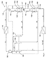
- a device for circulating a refrigerating fluid is formed by the components of a conventional refrigerating device, namely a main condenser 140, main expansion means such as a main isoenthalpic throttling valve 170, an evaporator 180 and a main compressor 190.
- the aforementioned conventional device is supplemented with certain components, enclosed ideally within a block - defined by broken lines in Figure 3 - which comprises a first and a second heat exchanger, 150, 152, respectively, for example heat exchangers of the plate or tube-bundle type, commonly used in the refrigerating sector, arranged in series between the condenser 140 and the main throttling valve 170, and a turbocompressor unit 160, inserted between the main compressor 190 and the evaporator 180 and provided with a compressor portion 166 and a first and second turbine portion 162, 164, which are respectively supplied by an outlet of each heat exchanger 150, 152.
- a first and a second heat exchanger, 150, 152 respectively, for example heat exchangers of the plate or tube-bundle type, commonly used in the refrigerating sector, arranged in series between the condenser 140 and the main throttling valve 170, and a turbocompressor unit 160, inserted between the main compressor 190 and the
- the condenser 140 is connected, via an inlet line 145, to a circuit for refrigerating fluid at a higher temperature, referred to below as “hot branch” 150c, of the first heat exchanger 150.
- the inlet line 145 has, branched off it, a line 146 which incorporates first expansion means, for example a first throttling valve 142, which leads into a circuit for a refrigerating fluid at a lower temperature, referred to below as “cold branch” 150f, of the first heat exchanger 150.
- the outlet of the hot branch 150c of the first heat exchanger 150 is linked, via a connection line 147, to the inlet of a circuit for refrigerating fluid at a higher temperature, referred to below as "hot branch" 152c, of the second heat exchanger 152, while the outlet of the cold branch 150f of the first heat exchanger 150 is connected to the inlet of the first turbine portion 162 of the turbocompressor unit 160.
- hot branch a circuit for refrigerating fluid at a higher temperature
- the line 147 connecting together the first and the second heat exchanger 150, 152 has a branch 148 provided with second expansion means, for example a second throttling valve 144, which leads into a circuit for refrigerating fluid at a lower temperature, referred to below as "cold branch” 152f, of the second heat exchanger 152.
- second expansion means for example a second throttling valve 144
- the outlet of the hot branch 152c of the second heat exchanger is connected, via an outlet line 149, to the main throttling valve 170, while the outlet of the cold branch 152f is connected to the inlet of the second turbine portion 164 of the turbocompressor unit 160.
- the outlet of the evaporator 180 is connected to the inlet of the compressor portion 166 of the turbocompressor unit 160, the outlet of which is in fluid communication with the main compressor 190.
- the refrigerating device is used for rapid freezing of alimentary products.
- the refrigerating device according to the present invention is suitable for many applications, for example the air-conditioning of domestic premises, so that, depending on the intended use, the pressure and temperature values of the physical states 1-14, as well as the type of refrigerating fluid circulating inside the device, will vary correspondingly.
- a portion of the refrigerating fluid flowing out from the condenser 140 referred to below as first bleed-off s1
- first bleed-off s1 A portion of the refrigerating fluid flowing out from the condenser 140, referred to below as first bleed-off s1
- first bleed-off s1 A portion of the refrigerating fluid flowing out from the condenser 140, referred to below as first bleed-off s1
- first bleed-off s1 A portion of the refrigerating fluid flowing out from the condenser 140, referred to below as first bleed-off s1
- the first and second bleed-offs of refrigerating fluid s1, s2 leaving each heat exchanger 150, 152 in the form of refrigerating fluid in the superheated vapour state are introduced, respectively, into the first and second turbine portion 162, 164 of the turbocompressor unit 160.
- the refrigerating fluid in the superheated vapour state leaving the evaporator 180 enters into the compressor portion 166 of the turbocompressor unit 160.
- This pre-compression stage offers considerable advantages. Firstly, since the mechanical energy is supplied by the bleed-offs s1, s2 which expand inside the turbines 162, 164, it is not required to use an external energy source. Secondly, the turbocompressor unit 160 compresses the refrigerating fluid, performing the work L TC ( Figure 4 ), when it is in the maximum specific volume condition, so that the main compressor 190 does not perform that part of the work which, in view of its constructional characteristics, penalizes its efficiency and in particular its processable mass flow, with a consequent reduction in the electric energy supplying the compressor itself.
- turbocompressor unit 160 has a fluid/dynamic connection with the main compressor 190 with the possibility of being able to adapt independently to the different load conditions without the aid of external control.
- cooling of the refrigerating fluid produced in the heat exchangers 150, 152 causes an increase in the performance of the evaporator 180, despite the fact that, following the bleed-offs s1, s2 there is, at the same time, a simultaneous reduction in the flow of refrigerating fluid into the evaporator 180.
- COP coefficient of performance
- the coefficient of performance COP is defined, in general, as the ratio between the heat Q subtracted from the lower temperature source, which constitutes the "amount of cold" produced, and the work L expended to cause operation of the refrigerating fluid circulation device.
- Table 2 below summarises the typical pressure, temperature and enthalpy values of a refrigerating fluid circulating inside a conventional refrigeration device of the type illustrated in Figures 1 and 2 .
- Table 2 Physical State p [bar] T [°C] h [Kj/Kg] 1 1.33 -35 347.6 2 16.1 65.3 416.9 3 16.1 35 254.8 4 1.33 -40 254.8
- a refrigerating device owing to the presence of the turbocompressor unit 160 and the consequent pre-compression of the refrigerating fluid circulating inside the device upstream of the main compressor 190, allows an increase in performance equal to about 30% to be obtained, all of which without the need for power supplied externally, but advantageously using the mechanical energy provided by one or more turbine portions 162, 164 of the turbocompressor unit 160, obtained by causing the expansion of one or more amounts s1, s2 of refrigerating fluid bled-off downstream of the condenser 140.
Landscapes
- Engineering & Computer Science (AREA)
- Physics & Mathematics (AREA)
- Mechanical Engineering (AREA)
- Thermal Sciences (AREA)
- General Engineering & Computer Science (AREA)
- Engine Equipment That Uses Special Cycles (AREA)
- Physical Or Chemical Processes And Apparatus (AREA)
- Devices That Are Associated With Refrigeration Equipment (AREA)
- Structures Of Non-Positive Displacement Pumps (AREA)
- Separation By Low-Temperature Treatments (AREA)
- Vaporization, Distillation, Condensation, Sublimation, And Cold Traps (AREA)
- Compression-Type Refrigeration Machines With Reversible Cycles (AREA)
- Supercharger (AREA)
- Heat-Exchange Devices With Radiators And Conduit Assemblies (AREA)
Claims (7)
- Kühlvorrichtung, aufweisend einen Hauptkompressor (190), einen Kondensator (140), dem Hauptkompressor (190) nachgeschaltet und im Fluidaustausch mit dem Hauptkompressor (190), Hauptexpansionsmittel (170), dem Kondensator (140) nachgeschaltet, ein Verdampfer (180), nachgeschaltet und im Fluidaustausch mit dem Hauptexpansionsmittel (170), eine Turbokompressoreinheit (160) aufweisend ein Kompressorteil (166) und einen ersten Turbinenteil (162), im Kühlfluidaustausch zwischen dem Verdampfer (180) und dem Hauptkompressor (190), und einem ersten Wärmetauscher (150), aufweisend einen heißen Strang (150c), zulaufseitig verbunden über eine Einlassleitung (145) mit dem Kondensator (140), und ablaufseitig, über eine Auslassleitung (149), mit dem Hauptexpansionsmittel (170),
dadurch gekennzeichnet, dass der mindestens eine Wärmetauscher (150, 152) einen kalten Strang (150f) aufweist, zulaufseitig verbunden zu einer Flussleitung (145), sich erstreckend zwischen dem Kondensator (140) und dem heißen Strang (150c) des ersten Wärmetauschers (150) durch eine Expansionsmittel (142), angebracht auf einem Zweig (146) der Leitung (145) und, abflussseitig, zu dem ersten Turbinenteil (162) der Turbokompressoreinheit (160), das Turbinenteil (162) ablassend abflussseitig vom Kompressorteil der Turbokompressoreinheit (160) und zuflussseitig von dem Hauptkompressor (190). - Vorrichtung gemäß Anspruch 1, dadurch gekennzeichnet, dass der erste Wärmetauscher (150) ein Röhrenbündelwärmetauscher ist.
- Vorrichtung gemäß Anspruch 1, dadurch gekennzeichnet, dass der erste Wärmetauscher (150) ein Plattenwärmetauscher ist.
- Vorrichtung gemäß Anspruch 1, dadurch gekennzeichnet, dass die Expansionsmittel (142) ein isoenthalpisches Drosselventil ist.
- Vorrichtung nach einem der Ansprüche 1 bis 4, dadurch gekennzeichnet, dass sie weiterhin einen zweiten Wärmetauscher (152) aufweist, angeordnet in Serie zwischen dem Wärmetauscher (140) und dem Hauptexpansionsmittel (170) und dass die Turbokompressoreinheit (160) weiterhin einen zweiten Turbinenteil (164) aufweist, wobei der zweite Wärmetauscher (152) einen heißen Strang (152c) aufweist, in Fluidaustausch, über eine Verbindungsleitung (147), mit dem heißen Strang (150c) des ersten Wärmetauschers und einen kalten Strang (152f) verbunden, zulaufseitig, zu einer Expansionsmittel (144), angebracht an einem Zweig (148) der Leitung (147) und, abflussseitig, mit dem zweiten Turbinenteil (164) der Turbokompressoreinheit (160), wobei der zweite Turbinenteil (164) abflussseitig des Kompressorteils der Turbokompressoreinheit (160) und zuflussseitig vom Hauptkompressor (190) abläuft.
- Verfahren zur Zirkulation eines Kühlfluids, aufweisend folgende Schritte:- Komprimieren des Kühlfluids in einem Hauptkompressor (190);- Kondensieren des Fluids in einem Kondensator (140) ablaufseitig von und in Fluidaustausch mit dem Hauptkompressor (190);- Expandieren des Fluids in einem Hauptexpansionsmittel (170) ablaufseitig von dem Kondensator (140);- Verdampfen des Fluids in einem Verdampfer (180) ablaufseitig von und in Kühlfluidaustausch mit dem Hauptexpansionsmittel (180);dadurch gekennzeichnet, dass sie aufweist:- zwischen der Kondensationsstufe und der Expansionsstufe eine Stufe beinhaltend einen Wärmeaustausch, innenhalb eines ersten Wärmetauschers (150), zwischen dem komprimierten Kühlfluid zirkulierend innerhalb eines heißen Stranges (150c) des ersten Wärmetauschers (150) und einer zugehörigen Menge (s1) des komprimierten Kühlfluids abgeflossen zulaufseitig vom ersten Wärmetauscher (150), gekühlt durch den Fluss durch ein Expansionsmittel (142) und in einem kalten Zweiges (150f) des Wärmetauschers (150); und- zwischen dem Hauptexpansionsmittel und der Hauptkompressionsstufe eine Stufe aufweisend eine Vorkompression des Kühlfluids innerhalb einer Turbokompressoreinheit (160), wobei die Vorkompressionsstufe eine Stufe aufweist, die eine Kompression innerhalb eines Kompressorteils (100) beinhaltet, und eine Stufe die eine Expansion, innerhalb eines ersten Turbinenteils (162) der Turbokompressoreinheit, von der abgeflossenen Menge (s1) des Kühlfluids, verlassend den kalten Strang (150f) des Wärmetauschers (150); und- eine Stufe, ablaufseitig, von dem Kompressorteil der Turbokompressoreinheit (160), und zulaufseitig vom Hauptkompressor (190), das Fluid ablassend, das den ersten Turbinenteil (162) verlässt.
- Verfahren gemäß Anspruch 6, dadurch gekennzeichnet, dass es aufweist abflussseitig der mindestens ersten Wärmeaustauschstufe zwischen der ersten Kondensationsstufe und der Expansionsstufe:- eine zweite Stufe aufweisend einen Wärmeaustausch in einem zweiten Wärmetauscher (152) angeordnet in Serie mit dem ersten Wärmetauscher (150) zwischen dem Kühlfluid verlassend den heißen Strang (150c) des zumindest einen Wärmetauschers (150) und zirkulierend innerhalb eines heißen Stranges (152c) des zweiten Wärmetauschers (152) und eine zugewiesene Menge (s2) des Kühlfluids abgeleitet zuflussseitig vom zweiten Wärmetauscher (152), abgefühlt innerhalb einer Expansionsmittel (144) und zirkulierend in einem kalten Strang (152f), die Expansion in der Vorkompressionsstufe weiterhin aufweisend eine Expansion in einem zweiten Turbinenteil (164) der Turbokompressoreinheit (160),wobei die Vorkompressionsstufe zwischen der Hauptexpansionsstufe und der Hauptkompressionsstufe angetrieben ist durch Expansion, in den ersten und zweiten Turbinenteilen (162, 164) der Turbokompressoreinheit (160), von den Abflüssen von jedem der Wärmetauscher (150, 152), und wobei das Fluid den zweiten Turbinenteil (164) verlässt und ablaufseitig des Kompressorteils der Turbokompressoreinheit (160) und zuflussseitig vom Hauptkompressor (190) abgeführt wird.
Priority Applications (2)
| Application Number | Priority Date | Filing Date | Title |
|---|---|---|---|
| SI200730941T SI2147265T1 (sl) | 2007-05-22 | 2007-05-22 | Hladilna priprava in postopek kroženja hladilne tekočine ki je z njo povezana |
| PL07736863T PL2147265T3 (pl) | 2007-05-22 | 2007-05-22 | Urządzenie chłodnicze i sposób krążenia związanego z nim płynu chłodniczego |
Applications Claiming Priority (1)
| Application Number | Priority Date | Filing Date | Title |
|---|---|---|---|
| PCT/IT2007/000360 WO2008142714A1 (en) | 2007-05-22 | 2007-05-22 | Refrigerating device and method for circulating a refrigerating fluid associated with it |
Publications (3)
| Publication Number | Publication Date |
|---|---|
| EP2147265A1 EP2147265A1 (de) | 2010-01-27 |
| EP2147265B1 true EP2147265B1 (de) | 2012-03-21 |
| EP2147265B8 EP2147265B8 (de) | 2012-04-25 |
Family
ID=38996662
Family Applications (1)
| Application Number | Title | Priority Date | Filing Date |
|---|---|---|---|
| EP07736863A Active EP2147265B8 (de) | 2007-05-22 | 2007-05-22 | Kühlvorrichtung und -verfahren zum zirkulieren eines ihr/ihm zugeordneten kühlfluids |
Country Status (16)
| Country | Link |
|---|---|
| US (1) | US8505317B2 (de) |
| EP (1) | EP2147265B8 (de) |
| JP (1) | JP5340271B2 (de) |
| KR (1) | KR101330193B1 (de) |
| CN (1) | CN101688702B (de) |
| AT (1) | ATE550612T1 (de) |
| AU (1) | AU2007353615B9 (de) |
| CA (1) | CA2687771C (de) |
| DK (1) | DK2147265T3 (de) |
| ES (1) | ES2384583T3 (de) |
| IL (1) | IL202099A0 (de) |
| MX (1) | MX2009012538A (de) |
| PL (1) | PL2147265T3 (de) |
| PT (1) | PT2147265E (de) |
| SI (1) | SI2147265T1 (de) |
| WO (1) | WO2008142714A1 (de) |
Families Citing this family (15)
| Publication number | Priority date | Publication date | Assignee | Title |
|---|---|---|---|---|
| JP5163161B2 (ja) * | 2008-02-01 | 2013-03-13 | ダイキン工業株式会社 | 暖房用補助ユニットおよび空気調和装置 |
| CN102257332B (zh) * | 2008-12-22 | 2013-08-14 | 松下电器产业株式会社 | 制冷循环装置 |
| BRPI1006298A2 (pt) * | 2009-04-01 | 2019-04-02 | Linum Systems Ltd | aparelho operado para prover ar condicionado e método para prover ar condicionado |
| JP5427563B2 (ja) | 2009-11-20 | 2014-02-26 | 三菱重工業株式会社 | インバータターボ冷凍機の性能評価装置 |
| JP5523972B2 (ja) | 2010-07-29 | 2014-06-18 | 三菱重工業株式会社 | ターボ冷凍機の性能評価装置 |
| JP5738116B2 (ja) | 2011-08-04 | 2015-06-17 | 三菱重工業株式会社 | ターボ冷凍機の性能評価装置およびその方法 |
| CN104315750B (zh) * | 2014-10-27 | 2016-07-27 | 势加透博(北京)科技有限公司 | 冷却气体压缩机进口气体的系统和方法 |
| ITUA20163047A1 (it) * | 2016-04-11 | 2016-07-11 | Giuseppe Verde | Macchina termica operatrice |
| FR3051546A1 (fr) * | 2016-05-19 | 2017-11-24 | Valeo Systemes Thermiques | Circuit de fluide refrigerant agence pour controler thermiquement une source d'energie |
| JP7175901B2 (ja) | 2017-01-30 | 2022-11-21 | ビツァー キュエールマシーネンバウ ゲゼルシャフト ミット ベシュレンクテル ハフツング | 冷媒回路内へ組み込むための膨張ユニット |
| IT201700098472A1 (it) * | 2017-09-01 | 2019-03-01 | Angelantoni Test Tech S R L In Breve Att S R L | Dispositivo di refrigerazione. |
| US10578342B1 (en) * | 2018-10-25 | 2020-03-03 | Ricardo Hiyagon Moromisato | Enhanced compression refrigeration cycle with turbo-compressor |
| KR102859077B1 (ko) * | 2018-10-26 | 2025-09-12 | 터보알고르 에스.알.엘. | 냉동 장치 및 그 작동 방법 |
| IT201900006560A1 (it) | 2019-05-07 | 2019-08-07 | Giuseppe Verde | Macchina termica a ciclo inverso a compressione di vapore |
| CN113865136A (zh) * | 2021-10-27 | 2021-12-31 | 珠海格力电器股份有限公司 | 空调系统 |
Citations (1)
| Publication number | Priority date | Publication date | Assignee | Title |
|---|---|---|---|---|
| EP0239680A2 (de) * | 1986-03-25 | 1987-10-07 | Mitsui Engineering and Shipbuilding Co, Ltd. | Wärmepumpe |
Family Cites Families (22)
| Publication number | Priority date | Publication date | Assignee | Title |
|---|---|---|---|---|
| DE2837695A1 (de) | 1977-08-29 | 1979-03-15 | Carrier Corp | Verfahren und vorrichtung zur wirkungsgradverbesserung in einer kuehlanlage |
| US4218891A (en) * | 1978-05-22 | 1980-08-26 | Schwartzman Everett H | Cooling and heat pump systems and methods |
| US4710824A (en) * | 1986-04-04 | 1987-12-01 | Polaroid Corporation | System and method for improving chrominance in video disc storage system |
| US5347823A (en) | 1990-04-06 | 1994-09-20 | Alsenz Richard H | Refrigeration system utilizing an enthalpy expansion jet compressor |
| RU1776939C (ru) | 1990-07-27 | 1992-11-23 | Государственный Макеевский Научно-Исследовательский Институт По Безопасности Работ В Горной Промышленности | Компрессионна холодильна машина |
| ES2171730T3 (es) | 1995-11-02 | 2002-09-16 | Aaf Mcquay Inc | Compresores en espiral. |
| WO1997039292A1 (en) * | 1996-04-18 | 1997-10-23 | Zakrytoe Aktsionernoe Obschestvo Nauchno-Proizvodstvennoe Obiedinenie 'vik' | 5 OR 8 kW REFRIGERATING SYSTEM AND CENTRIFUGAL COMPRESSOR ASSEMBLY FOR SAID SYSTEM |
| US5768901A (en) * | 1996-12-02 | 1998-06-23 | Carrier Corporation | Refrigerating system employing a compressor for single or multi-stage operation with capacity control |
| EP0943422B1 (de) * | 1998-03-16 | 2004-05-19 | Yamada Dobby Co., Ltd. | Steuervorrichtung für den Stössel einer Presse |
| US6321564B1 (en) * | 1999-03-15 | 2001-11-27 | Denso Corporation | Refrigerant cycle system with expansion energy recovery |
| JP4186398B2 (ja) | 2000-08-23 | 2008-11-26 | 株式会社島津製作所 | 輸送機械用空調装置 |
| JP3903851B2 (ja) * | 2002-06-11 | 2007-04-11 | 株式会社デンソー | 熱交換器 |
| US6644045B1 (en) * | 2002-06-25 | 2003-11-11 | Carrier Corporation | Oil free screw expander-compressor |
| US6694750B1 (en) * | 2002-08-21 | 2004-02-24 | Carrier Corporation | Refrigeration system employing multiple economizer circuits |
| JP4069733B2 (ja) | 2002-11-29 | 2008-04-02 | 三菱電機株式会社 | 空気調和機 |
| JP4055902B2 (ja) * | 2003-04-28 | 2008-03-05 | 株式会社日立製作所 | 膨張機を備えた冷凍装置 |
| JP4581795B2 (ja) | 2005-03-31 | 2010-11-17 | ダイキン工業株式会社 | 冷凍装置 |
| US7669428B2 (en) * | 2005-04-14 | 2010-03-02 | Georgia Tech Research Corporation | Vortex tube refrigeration systems and methods |
| EP1775531A1 (de) | 2005-10-12 | 2007-04-18 | GTI Koudetechnik B.V. | Gerät und System zum Kühlen und/oder Gefrieren und zum Abtauen |
| US7987683B2 (en) * | 2006-02-20 | 2011-08-02 | Hamilton Sundstrand Corporation | Expendable turbine driven compression cycle cooling system |
| EP2008039B1 (de) * | 2006-03-27 | 2016-11-02 | Carrier Corporation | Kühlsystem mit parallelen, mehrstufigen economiser-kreisläufen mit abführung auf zwischenstufendrücken eines hauptverdichters |
| WO2008115227A1 (en) * | 2007-03-16 | 2008-09-25 | Carrier Corporation | Refrigerant system with variable capacity expander |
-
2007
- 2007-05-22 DK DK07736863.7T patent/DK2147265T3/da active
- 2007-05-22 CA CA2687771A patent/CA2687771C/en not_active Expired - Fee Related
- 2007-05-22 CN CN2007800530542A patent/CN101688702B/zh not_active Expired - Fee Related
- 2007-05-22 KR KR1020097026526A patent/KR101330193B1/ko not_active Expired - Fee Related
- 2007-05-22 WO PCT/IT2007/000360 patent/WO2008142714A1/en not_active Ceased
- 2007-05-22 PT PT07736863T patent/PT2147265E/pt unknown
- 2007-05-22 US US12/601,060 patent/US8505317B2/en active Active
- 2007-05-22 SI SI200730941T patent/SI2147265T1/sl unknown
- 2007-05-22 MX MX2009012538A patent/MX2009012538A/es active IP Right Grant
- 2007-05-22 JP JP2010508971A patent/JP5340271B2/ja not_active Expired - Fee Related
- 2007-05-22 EP EP07736863A patent/EP2147265B8/de active Active
- 2007-05-22 ES ES07736863T patent/ES2384583T3/es active Active
- 2007-05-22 AT AT07736863T patent/ATE550612T1/de active
- 2007-05-22 PL PL07736863T patent/PL2147265T3/pl unknown
- 2007-05-22 AU AU2007353615A patent/AU2007353615B9/en not_active Ceased
-
2009
- 2009-11-12 IL IL202099A patent/IL202099A0/en unknown
Patent Citations (1)
| Publication number | Priority date | Publication date | Assignee | Title |
|---|---|---|---|---|
| EP0239680A2 (de) * | 1986-03-25 | 1987-10-07 | Mitsui Engineering and Shipbuilding Co, Ltd. | Wärmepumpe |
Also Published As
| Publication number | Publication date |
|---|---|
| AU2007353615A1 (en) | 2008-11-27 |
| DK2147265T3 (da) | 2012-07-02 |
| JP5340271B2 (ja) | 2013-11-13 |
| MX2009012538A (es) | 2010-02-12 |
| WO2008142714A1 (en) | 2008-11-27 |
| ATE550612T1 (de) | 2012-04-15 |
| CA2687771C (en) | 2013-07-09 |
| US20100162740A1 (en) | 2010-07-01 |
| KR20100038172A (ko) | 2010-04-13 |
| CN101688702B (zh) | 2011-05-04 |
| CN101688702A (zh) | 2010-03-31 |
| KR101330193B1 (ko) | 2013-11-18 |
| PT2147265E (pt) | 2012-06-26 |
| IL202099A0 (en) | 2010-06-16 |
| PL2147265T3 (pl) | 2012-12-31 |
| SI2147265T1 (sl) | 2012-07-31 |
| EP2147265B8 (de) | 2012-04-25 |
| HK1137051A1 (en) | 2010-07-16 |
| JP2010528250A (ja) | 2010-08-19 |
| ES2384583T3 (es) | 2012-07-09 |
| US8505317B2 (en) | 2013-08-13 |
| EP2147265A1 (de) | 2010-01-27 |
| AU2007353615B9 (en) | 2012-04-19 |
| CA2687771A1 (en) | 2008-11-27 |
| AU2007353615B2 (en) | 2012-04-12 |
Similar Documents
| Publication | Publication Date | Title |
|---|---|---|
| EP2147265B1 (de) | Kühlvorrichtung und -verfahren zum zirkulieren eines ihr/ihm zugeordneten kühlfluids | |
| US6698234B2 (en) | Method for increasing efficiency of a vapor compression system by evaporator heating | |
| US6941763B2 (en) | Heat pump and dehumidifying apparatus | |
| US6460371B2 (en) | Multistage compression refrigerating machine for supplying refrigerant from subcooler to cool rotating machine and lubricating oil | |
| CN100491866C (zh) | 一种多级串联大温差压缩式热泵机组 | |
| CN109708337B (zh) | 多级串联压缩式热泵机组 | |
| JP2008541000A (ja) | ヒートポンプ装置および流体の加熱方法 | |
| CN109269136B (zh) | 空调系统 | |
| CN110486943A (zh) | 多级压缩多冷凝器中间节流不完全冷却中高温热泵系统 | |
| CN109682104B (zh) | 冷媒循环系统和空调器 | |
| US20080184722A1 (en) | Method and apparatus for a refrigeration circuit | |
| RU2432531C2 (ru) | Холодильное устройство и способ циркуляции в нем охлаждающей текучей среды | |
| JP4814823B2 (ja) | 冷凍装置 | |
| HK1137051B (en) | Refrigerating device and method for circulating a refrigerating fluid associated with it | |
| CN210070283U (zh) | 冷媒循环系统和空调器 | |
| KR101178700B1 (ko) | 다단 직렬 압축 방식의 히트펌프 시스템 | |
| US20040118133A1 (en) | Heat pump and dehumidifying air-conditioning apparatus | |
| US7555915B2 (en) | Air conditioner | |
| CN213335032U (zh) | 一种制冷系统 | |
| KR20070071793A (ko) | 공기조화기의 냉매 순환구조 | |
| KR200214007Y1 (ko) | 저 압축부하형 냉방장치 | |
| KR100512103B1 (ko) | 냉동 시스템 | |
| KR100252655B1 (ko) | 공기조화기의 열교환기 패스라인구조 | |
| KR20050075804A (ko) | 열펌프시스템 | |
| HK1138353A (en) | Refrigerant system with economizer, intercooler and multi-stage compressor |
Legal Events
| Date | Code | Title | Description |
|---|---|---|---|
| PUAI | Public reference made under article 153(3) epc to a published international application that has entered the european phase |
Free format text: ORIGINAL CODE: 0009012 |
|
| 17P | Request for examination filed |
Effective date: 20091110 |
|
| AK | Designated contracting states |
Kind code of ref document: A1 Designated state(s): AT BE BG CH CY CZ DE DK EE ES FI FR GB GR HU IE IS IT LI LT LU LV MC MT NL PL PT RO SE SI SK TR |
|
| AX | Request for extension of the european patent |
Extension state: AL BA HR MK RS |
|
| 17Q | First examination report despatched |
Effective date: 20100420 |
|
| REG | Reference to a national code |
Ref country code: HK Ref legal event code: DE Ref document number: 1137051 Country of ref document: HK |
|
| DAX | Request for extension of the european patent (deleted) | ||
| REG | Reference to a national code |
Ref country code: DE Ref legal event code: R079 Ref document number: 602007021460 Country of ref document: DE Free format text: PREVIOUS MAIN CLASS: F25B0001053000 Ipc: F25B0011020000 |
|
| RIC1 | Information provided on ipc code assigned before grant |
Ipc: F25B 1/10 20060101ALI20111025BHEP Ipc: F25B 1/053 20060101ALI20111025BHEP Ipc: F25B 11/02 20060101AFI20111025BHEP |
|
| GRAP | Despatch of communication of intention to grant a patent |
Free format text: ORIGINAL CODE: EPIDOSNIGR1 |
|
| GRAS | Grant fee paid |
Free format text: ORIGINAL CODE: EPIDOSNIGR3 |
|
| GRAA | (expected) grant |
Free format text: ORIGINAL CODE: 0009210 |
|
| AK | Designated contracting states |
Kind code of ref document: B1 Designated state(s): AT BE BG CH CY CZ DE DK EE ES FI FR GB GR HU IE IS IT LI LT LU LV MC MT NL PL PT RO SE SI SK TR |
|
| REG | Reference to a national code |
Ref country code: GB Ref legal event code: FG4D |
|
| RAP2 | Party data changed (patent owner data changed or rights of a patent transferred) |
Owner name: ANGELANTONI LIFE SCIENCE S.R.L. |
|
| REG | Reference to a national code |
Ref country code: CH Ref legal event code: EP |
|
| REG | Reference to a national code |
Ref country code: IE Ref legal event code: FG4D |
|
| REG | Reference to a national code |
Ref country code: AT Ref legal event code: REF Ref document number: 550612 Country of ref document: AT Kind code of ref document: T Effective date: 20120415 |
|
| RAP2 | Party data changed (patent owner data changed or rights of a patent transferred) |
Owner name: ALS S.R.L. |
|
| REG | Reference to a national code |
Ref country code: DE Ref legal event code: R081 Ref document number: 602007021460 Country of ref document: DE Owner name: TURBOALGOR S.R.L., IT Free format text: FORMER OWNER: ANGELANTONI INDUSTRIE S.P.A., MASSA MARTANA, PERUGIA, IT |
|
| REG | Reference to a national code |
Ref country code: DE Ref legal event code: R096 Ref document number: 602007021460 Country of ref document: DE Effective date: 20120516 |
|
| REG | Reference to a national code |
Ref country code: RO Ref legal event code: EPE |
|
| REG | Reference to a national code |
Ref country code: PT Ref legal event code: SC4A Free format text: AVAILABILITY OF NATIONAL TRANSLATION Effective date: 20120618 |
|
| RAP2 | Party data changed (patent owner data changed or rights of a patent transferred) |
Owner name: ANGELANTONI CLEANTECH SRL |
|
| REG | Reference to a national code |
Ref country code: NL Ref legal event code: T3 |
|
| REG | Reference to a national code |
Ref country code: CH Ref legal event code: NV Representative=s name: PATENTANWAELTE SCHAAD, BALASS, MENZL & PARTNER AG Ref country code: CH Ref legal event code: PUE Owner name: ANGELANTONI CLEANTECH SRL Free format text: ALS S.R.L.#LOCALITA CIMACOLLE 464#06056 MASSA MARTANA (PG) (IT) -TRANSFER TO- ANGELANTONI CLEANTECH SRL#LOCALITA CIMACOLLE 464#06056 MASSA MARTANA (PG) (IT) |
|
| REG | Reference to a national code |
Ref country code: DK Ref legal event code: T3 Ref country code: DE Ref legal event code: R081 Ref document number: 602007021460 Country of ref document: DE Owner name: TURBOALGOR S.R.L., IT Free format text: FORMER OWNER: ALS S.R.L., MASSA MARTANA, IT |
|
| REG | Reference to a national code |
Ref country code: ES Ref legal event code: FG2A Ref document number: 2384583 Country of ref document: ES Kind code of ref document: T3 Effective date: 20120709 |
|
| REG | Reference to a national code |
Ref country code: SE Ref legal event code: TRGR |
|
| REG | Reference to a national code |
Ref country code: EE Ref legal event code: FG4A Ref document number: E006800 Country of ref document: EE Effective date: 20120621 |
|
| REG | Reference to a national code |
Ref country code: GR Ref legal event code: EP Ref document number: 20120401406 Country of ref document: GR Effective date: 20120713 |
|
| REG | Reference to a national code |
Ref country code: AT Ref legal event code: HC Ref document number: 550612 Country of ref document: AT Kind code of ref document: T Owner name: ALS S.R.L., IT Effective date: 20120716 |
|
| REG | Reference to a national code |
Ref country code: GB Ref legal event code: 732E Free format text: REGISTERED BETWEEN 20120830 AND 20120905 |
|
| PG25 | Lapsed in a contracting state [announced via postgrant information from national office to epo] |
Ref country code: CY Free format text: LAPSE BECAUSE OF FAILURE TO SUBMIT A TRANSLATION OF THE DESCRIPTION OR TO PAY THE FEE WITHIN THE PRESCRIBED TIME-LIMIT Effective date: 20120321 |
|
| REG | Reference to a national code |
Ref country code: EE Ref legal event code: HB1A Ref document number: E006800 Country of ref document: EE |
|
| REG | Reference to a national code |
Ref country code: PT Ref legal event code: PC4A Owner name: ANGELANTONI CLEANTECH SRL, IT Effective date: 20121012 |
|
| PG25 | Lapsed in a contracting state [announced via postgrant information from national office to epo] |
Ref country code: IS Free format text: LAPSE BECAUSE OF FAILURE TO SUBMIT A TRANSLATION OF THE DESCRIPTION OR TO PAY THE FEE WITHIN THE PRESCRIBED TIME-LIMIT Effective date: 20120721 |
|
| REG | Reference to a national code |
Ref country code: HU Ref legal event code: AG4A Ref document number: E014325 Country of ref document: HU |
|
| REG | Reference to a national code |
Ref country code: HK Ref legal event code: GR Ref document number: 1137051 Country of ref document: HK |
|
| PG25 | Lapsed in a contracting state [announced via postgrant information from national office to epo] |
Ref country code: MC Free format text: LAPSE BECAUSE OF NON-PAYMENT OF DUE FEES Effective date: 20120531 |
|
| REG | Reference to a national code |
Ref country code: PL Ref legal event code: T3 |
|
| REG | Reference to a national code |
Ref country code: SK Ref legal event code: T3 Ref document number: E 12676 Country of ref document: SK |
|
| PLBE | No opposition filed within time limit |
Free format text: ORIGINAL CODE: 0009261 |
|
| STAA | Information on the status of an ep patent application or granted ep patent |
Free format text: STATUS: NO OPPOSITION FILED WITHIN TIME LIMIT |
|
| 26N | No opposition filed |
Effective date: 20130102 |
|
| REG | Reference to a national code |
Ref country code: DE Ref legal event code: R097 Ref document number: 602007021460 Country of ref document: DE Effective date: 20130102 |
|
| PG25 | Lapsed in a contracting state [announced via postgrant information from national office to epo] |
Ref country code: MT Free format text: LAPSE BECAUSE OF FAILURE TO SUBMIT A TRANSLATION OF THE DESCRIPTION OR TO PAY THE FEE WITHIN THE PRESCRIBED TIME-LIMIT Effective date: 20120321 |
|
| PGFP | Annual fee paid to national office [announced via postgrant information from national office to epo] |
Ref country code: LT Payment date: 20130502 Year of fee payment: 7 Ref country code: LU Payment date: 20130531 Year of fee payment: 7 Ref country code: EE Payment date: 20130507 Year of fee payment: 7 Ref country code: SK Payment date: 20130503 Year of fee payment: 7 Ref country code: CZ Payment date: 20130515 Year of fee payment: 7 Ref country code: IE Payment date: 20130528 Year of fee payment: 7 |
|
| PGFP | Annual fee paid to national office [announced via postgrant information from national office to epo] |
Ref country code: RO Payment date: 20130510 Year of fee payment: 7 Ref country code: SI Payment date: 20130510 Year of fee payment: 7 Ref country code: LV Payment date: 20130507 Year of fee payment: 7 Ref country code: HU Payment date: 20130515 Year of fee payment: 7 Ref country code: FI Payment date: 20130530 Year of fee payment: 7 |
|
| PGFP | Annual fee paid to national office [announced via postgrant information from national office to epo] |
Ref country code: BG Payment date: 20130530 Year of fee payment: 7 |
|
| REG | Reference to a national code |
Ref country code: LT Ref legal event code: MM4D Effective date: 20140522 |
|
| PG25 | Lapsed in a contracting state [announced via postgrant information from national office to epo] |
Ref country code: LU Free format text: LAPSE BECAUSE OF NON-PAYMENT OF DUE FEES Effective date: 20140522 |
|
| REG | Reference to a national code |
Ref country code: EE Ref legal event code: MM4A Ref document number: E006800 Country of ref document: EE Effective date: 20140531 |
|
| PG25 | Lapsed in a contracting state [announced via postgrant information from national office to epo] |
Ref country code: EE Free format text: LAPSE BECAUSE OF NON-PAYMENT OF DUE FEES Effective date: 20140531 Ref country code: RO Free format text: LAPSE BECAUSE OF NON-PAYMENT OF DUE FEES Effective date: 20140522 Ref country code: LT Free format text: LAPSE BECAUSE OF NON-PAYMENT OF DUE FEES Effective date: 20140522 Ref country code: CZ Free format text: LAPSE BECAUSE OF NON-PAYMENT OF DUE FEES Effective date: 20140522 Ref country code: SK Free format text: LAPSE BECAUSE OF NON-PAYMENT OF DUE FEES Effective date: 20140522 Ref country code: FI Free format text: LAPSE BECAUSE OF NON-PAYMENT OF DUE FEES Effective date: 20140522 Ref country code: BG Free format text: LAPSE BECAUSE OF NON-PAYMENT OF DUE FEES Effective date: 20141231 |
|
| REG | Reference to a national code |
Ref country code: SK Ref legal event code: MM4A Ref document number: E 12676 Country of ref document: SK Effective date: 20140522 |
|
| REG | Reference to a national code |
Ref country code: IE Ref legal event code: MM4A |
|
| PG25 | Lapsed in a contracting state [announced via postgrant information from national office to epo] |
Ref country code: SI Free format text: LAPSE BECAUSE OF NON-PAYMENT OF DUE FEES Effective date: 20140523 Ref country code: LV Free format text: LAPSE BECAUSE OF NON-PAYMENT OF DUE FEES Effective date: 20140522 Ref country code: HU Free format text: LAPSE BECAUSE OF NON-PAYMENT OF DUE FEES Effective date: 20140523 |
|
| REG | Reference to a national code |
Ref country code: SI Ref legal event code: KO00 Effective date: 20150106 |
|
| PG25 | Lapsed in a contracting state [announced via postgrant information from national office to epo] |
Ref country code: IE Free format text: LAPSE BECAUSE OF NON-PAYMENT OF DUE FEES Effective date: 20140522 |
|
| REG | Reference to a national code |
Ref country code: FR Ref legal event code: PLFP Year of fee payment: 10 |
|
| REG | Reference to a national code |
Ref country code: CH Ref legal event code: NV Representative=s name: FABIANO, FRANKE AND MGT SAGL, CH |
|
| REG | Reference to a national code |
Ref country code: DE Ref legal event code: R082 Ref document number: 602007021460 Country of ref document: DE Representative=s name: MAIWALD PATENTANWALTSGESELLSCHAFT MBH, DE Ref country code: DE Ref legal event code: R082 Ref document number: 602007021460 Country of ref document: DE Representative=s name: MAIWALD PATENTANWALTS- UND RECHTSANWALTSGESELL, DE Ref country code: DE Ref legal event code: R081 Ref document number: 602007021460 Country of ref document: DE Owner name: TURBOALGOR S.R.L., IT Free format text: FORMER OWNER: ANGELANTONI CLEANTECH SRL, MASSA MARTANA, IT |
|
| REG | Reference to a national code |
Ref country code: CH Ref legal event code: PFA Owner name: TURBOALGOR S.R.L., IT Free format text: FORMER OWNER: ANGELANTONI CLEANTECH SRL, IT |
|
| REG | Reference to a national code |
Ref country code: FR Ref legal event code: PLFP Year of fee payment: 11 |
|
| REG | Reference to a national code |
Ref country code: GB Ref legal event code: 732E Free format text: REGISTERED BETWEEN 20170615 AND 20170621 |
|
| REG | Reference to a national code |
Ref country code: FR Ref legal event code: PLFP Year of fee payment: 12 |
|
| REG | Reference to a national code |
Ref country code: CH Ref legal event code: PCAR Free format text: NEW ADDRESS: PIAZZETTA SAN CARLO 2, 6900 LUGANO (CH) |
|
| PGFP | Annual fee paid to national office [announced via postgrant information from national office to epo] |
Ref country code: GR Payment date: 20200330 Year of fee payment: 14 Ref country code: PT Payment date: 20200326 Year of fee payment: 14 |
|
| PGFP | Annual fee paid to national office [announced via postgrant information from national office to epo] |
Ref country code: TR Payment date: 20200325 Year of fee payment: 14 |
|
| PG25 | Lapsed in a contracting state [announced via postgrant information from national office to epo] |
Ref country code: PT Free format text: LAPSE BECAUSE OF NON-PAYMENT OF DUE FEES Effective date: 20211122 |
|
| PG25 | Lapsed in a contracting state [announced via postgrant information from national office to epo] |
Ref country code: GR Free format text: LAPSE BECAUSE OF NON-PAYMENT OF DUE FEES Effective date: 20211207 |
|
| PG25 | Lapsed in a contracting state [announced via postgrant information from national office to epo] |
Ref country code: TR Free format text: LAPSE BECAUSE OF NON-PAYMENT OF DUE FEES Effective date: 20210522 |
|
| PGFP | Annual fee paid to national office [announced via postgrant information from national office to epo] |
Ref country code: NL Payment date: 20230526 Year of fee payment: 17 Ref country code: DK Payment date: 20230524 Year of fee payment: 17 Ref country code: CH Payment date: 20230602 Year of fee payment: 17 |
|
| PGFP | Annual fee paid to national office [announced via postgrant information from national office to epo] |
Ref country code: SE Payment date: 20230516 Year of fee payment: 17 Ref country code: AT Payment date: 20230330 Year of fee payment: 17 |
|
| PGFP | Annual fee paid to national office [announced via postgrant information from national office to epo] |
Ref country code: BE Payment date: 20230412 Year of fee payment: 17 |
|
| REG | Reference to a national code |
Ref country code: ES Ref legal event code: PC2A Owner name: TURBOALGOR S.R.L. Effective date: 20240424 |
|
| REG | Reference to a national code |
Ref country code: CH Ref legal event code: PL |
|
| REG | Reference to a national code |
Ref country code: DK Ref legal event code: EBP Effective date: 20240531 Ref country code: SE Ref legal event code: EUG |
|
| REG | Reference to a national code |
Ref country code: NL Ref legal event code: MM Effective date: 20240601 |
|
| REG | Reference to a national code |
Ref country code: AT Ref legal event code: MM01 Ref document number: 550612 Country of ref document: AT Kind code of ref document: T Effective date: 20240522 |
|
| PG25 | Lapsed in a contracting state [announced via postgrant information from national office to epo] |
Ref country code: AT Free format text: LAPSE BECAUSE OF NON-PAYMENT OF DUE FEES Effective date: 20240522 |
|
| PG25 | Lapsed in a contracting state [announced via postgrant information from national office to epo] |
Ref country code: AT Free format text: LAPSE BECAUSE OF NON-PAYMENT OF DUE FEES Effective date: 20240522 Ref country code: CH Free format text: LAPSE BECAUSE OF NON-PAYMENT OF DUE FEES Effective date: 20240531 |
|
| PG25 | Lapsed in a contracting state [announced via postgrant information from national office to epo] |
Ref country code: NL Free format text: LAPSE BECAUSE OF NON-PAYMENT OF DUE FEES Effective date: 20240601 |
|
| REG | Reference to a national code |
Ref country code: BE Ref legal event code: MM Effective date: 20240531 |
|
| PG25 | Lapsed in a contracting state [announced via postgrant information from national office to epo] |
Ref country code: DK Free format text: LAPSE BECAUSE OF NON-PAYMENT OF DUE FEES Effective date: 20240531 |
|
| PG25 | Lapsed in a contracting state [announced via postgrant information from national office to epo] |
Ref country code: BE Free format text: LAPSE BECAUSE OF NON-PAYMENT OF DUE FEES Effective date: 20240531 |
|
| PGFP | Annual fee paid to national office [announced via postgrant information from national office to epo] |
Ref country code: DE Payment date: 20250528 Year of fee payment: 19 Ref country code: PL Payment date: 20250422 Year of fee payment: 19 |
|
| PGFP | Annual fee paid to national office [announced via postgrant information from national office to epo] |
Ref country code: GB Payment date: 20250512 Year of fee payment: 19 Ref country code: ES Payment date: 20250603 Year of fee payment: 19 |
|
| PGFP | Annual fee paid to national office [announced via postgrant information from national office to epo] |
Ref country code: IT Payment date: 20250509 Year of fee payment: 19 |
|
| PGFP | Annual fee paid to national office [announced via postgrant information from national office to epo] |
Ref country code: FR Payment date: 20250528 Year of fee payment: 19 |
|
| PG25 | Lapsed in a contracting state [announced via postgrant information from national office to epo] |
Ref country code: SE Free format text: LAPSE BECAUSE OF NON-PAYMENT OF DUE FEES Effective date: 20240523 |