EP2147881A2 - Auslagevorrichtung für flache Produkte - Google Patents
Auslagevorrichtung für flache Produkte Download PDFInfo
- Publication number
- EP2147881A2 EP2147881A2 EP09164915A EP09164915A EP2147881A2 EP 2147881 A2 EP2147881 A2 EP 2147881A2 EP 09164915 A EP09164915 A EP 09164915A EP 09164915 A EP09164915 A EP 09164915A EP 2147881 A2 EP2147881 A2 EP 2147881A2
- Authority
- EP
- European Patent Office
- Prior art keywords
- stacks
- stack
- plane
- forming
- further processing
- Prior art date
- Legal status (The legal status is an assumption and is not a legal conclusion. Google has not performed a legal analysis and makes no representation as to the accuracy of the status listed.)
- Withdrawn
Links
- 238000000151 deposition Methods 0.000 title 1
- 238000000034 method Methods 0.000 claims abstract description 7
- 239000011111 cardboard Substances 0.000 claims abstract description 4
- 230000001360 synchronised effect Effects 0.000 claims description 4
- 239000000123 paper Substances 0.000 claims description 3
- 230000008878 coupling Effects 0.000 claims description 2
- 238000010168 coupling process Methods 0.000 claims description 2
- 238000005859 coupling reaction Methods 0.000 claims description 2
- 230000032258 transport Effects 0.000 abstract 5
- 239000011087 paperboard Substances 0.000 abstract 1
- 230000015572 biosynthetic process Effects 0.000 description 3
- 238000004806 packaging method and process Methods 0.000 description 3
- 239000000969 carrier Substances 0.000 description 1
- 238000010276 construction Methods 0.000 description 1
- 230000001419 dependent effect Effects 0.000 description 1
- 239000000463 material Substances 0.000 description 1
Images



Classifications
-
- B—PERFORMING OPERATIONS; TRANSPORTING
- B65—CONVEYING; PACKING; STORING; HANDLING THIN OR FILAMENTARY MATERIAL
- B65H—HANDLING THIN OR FILAMENTARY MATERIAL, e.g. SHEETS, WEBS, CABLES
- B65H31/00—Pile receivers
- B65H31/30—Arrangements for removing completed piles
- B65H31/3081—Arrangements for removing completed piles by acting on edge of the pile for moving it along a surface, e.g. by pushing
-
- B—PERFORMING OPERATIONS; TRANSPORTING
- B65—CONVEYING; PACKING; STORING; HANDLING THIN OR FILAMENTARY MATERIAL
- B65G—TRANSPORT OR STORAGE DEVICES, e.g. CONVEYORS FOR LOADING OR TIPPING, SHOP CONVEYOR SYSTEMS OR PNEUMATIC TUBE CONVEYORS
- B65G47/00—Article or material-handling devices associated with conveyors; Methods employing such devices
- B65G47/52—Devices for transferring articles or materials between conveyors i.e. discharging or feeding devices
- B65G47/64—Switching conveyors
- B65G47/641—Switching conveyors by a linear displacement of the switching conveyor
- B65G47/643—Switching conveyors by a linear displacement of the switching conveyor in a vertical plane
-
- B—PERFORMING OPERATIONS; TRANSPORTING
- B65—CONVEYING; PACKING; STORING; HANDLING THIN OR FILAMENTARY MATERIAL
- B65H—HANDLING THIN OR FILAMENTARY MATERIAL, e.g. SHEETS, WEBS, CABLES
- B65H31/00—Pile receivers
- B65H31/24—Pile receivers multiple or compartmented, e.d. for alternate, programmed, or selective filling
-
- B—PERFORMING OPERATIONS; TRANSPORTING
- B65—CONVEYING; PACKING; STORING; HANDLING THIN OR FILAMENTARY MATERIAL
- B65H—HANDLING THIN OR FILAMENTARY MATERIAL, e.g. SHEETS, WEBS, CABLES
- B65H2301/00—Handling processes for sheets or webs
- B65H2301/40—Type of handling process
- B65H2301/42—Piling, depiling, handling piles
- B65H2301/422—Handling piles, sets or stacks of articles
- B65H2301/4226—Delivering, advancing piles
- B65H2301/42264—Delivering, advancing piles by moving the surface supporting the lowermost article of the pile, e.g. conveyor, carriage
-
- B—PERFORMING OPERATIONS; TRANSPORTING
- B65—CONVEYING; PACKING; STORING; HANDLING THIN OR FILAMENTARY MATERIAL
- B65H—HANDLING THIN OR FILAMENTARY MATERIAL, e.g. SHEETS, WEBS, CABLES
- B65H2301/00—Handling processes for sheets or webs
- B65H2301/40—Type of handling process
- B65H2301/42—Piling, depiling, handling piles
- B65H2301/422—Handling piles, sets or stacks of articles
- B65H2301/4226—Delivering, advancing piles
- B65H2301/42266—Delivering, advancing piles by acting on edge of the pile for moving it along a surface, e.g. pushing
-
- B—PERFORMING OPERATIONS; TRANSPORTING
- B65—CONVEYING; PACKING; STORING; HANDLING THIN OR FILAMENTARY MATERIAL
- B65H—HANDLING THIN OR FILAMENTARY MATERIAL, e.g. SHEETS, WEBS, CABLES
- B65H2701/00—Handled material; Storage means
- B65H2701/10—Handled articles or webs
- B65H2701/17—Nature of material
- B65H2701/176—Cardboard
Definitions
- the invention relates to a display device for flat products according to the preamble of claim 1 as well as a method for operating a display device according to claim 10.
- the actual processing station is followed by a display for the processed products.
- the products, d. H. folded signatures, brochures or books are either designed to be scaled or a specific and predetermined number of products are stored on a stack.
- Printed products arriving at a first level in a scale flow are stacked, the stack is moved vertically downwards into a strapping device and provided there with a strapping band.
- a device of similar construction also shows the DE 37 05 169 C2 : Printed products arriving on a conveyor belt in a first level are collected and stacked. The stack is transported by means of a transfer device vertically down to a packaging device, where the stack is provided with a band. In the plane of Packaging device and then to the packaging device is a conveyor belt for removing the banded stack.
- the object of the present invention is to provide a display device for flat products, in which stacks formed on two levels can be transferred to a subsequent device for further processing, such as a device for banding.
- the display device for flat products of paper, cardboard and the like comprises a device for forming stacks of the products and subsequently a device for further processing of the stacks.
- the stack forming apparatus has at least two substantially horizontal planes in which the stacks are formed.
- the device for further processing of the stack has only a substantially horizontal plane in which the stacks are processed.
- the stacks are transported further in the transport direction by means familiar to the person skilled in the art.
- a transport device is advantageously mounted for transporting the stacks from the respective plane of the apparatus for forming stacks to the one level of the apparatus for further processing the stacks.
- the stacks are each transported by a transfer device.
- the transfer device can be, for example, horizontally moved carriers, moving grippers, a driven roller conveyor or driven conveyor belts.
- the invention also relates to a display device for flat products of paper, cardboard and the like with a device for banding.
- the products may be in particular to signatures or brochures, which are passed from a further processing machine, in particular a folding machine or a saddle stitcher to the delivery device.
- the delivery device comprises a delivery device, subsequently a device for forming stacks of the products and subsequently a device for banding the stacks.
- Banderolieren means the lending of the stack with a banderole or the strapping of the stack with a strapping.
- the apparatus for forming stacks has at least two levels, wherein stacks are formed in each level.
- the banding apparatus has a plane in which the stacks are banded.
- a transport means for transporting the stacks from the respective plane of the stack forming apparatus to the one level of the banding apparatus.
- the transport device thus allows the merging of the material flow, ie the merging of the stack of two levels on a plane. Tapes and input and Ausschubstoff can be driven in an electric motor known manner in the art.
- To the device for banding may be followed by a device for transporting the stack, which has a memory link.
- An advantage of such a delivery device is that only one device for banding is needed and the cost of the delivery device can thus be kept low.
- By a corresponding control of the transport device can be stacked with the display device flat products with a high clock frequency, banded and designed.
- the device for forming stacks, the transport device and the device for banding are connected to a control device.
- the clock frequencies with which the apparatus for forming stacks, the transport device and the device for banding can be operated, can be advantageously controlled by the control device and synchronized relative to each other.
- the transport device has a liftable receiving plane.
- the liftable receiving plane can perform a lifting movement between an upper and a lower reversal point.
- the receiving plane can be driven by a motor in the known manner in the art.
- the upper reversal point is at the level of the upper level of the apparatus for forming stacks
- the lower reversal point is at the level of the lower level of the apparatus for forming stacks.
- the plane of the device for banding lies between the upper and the lower reversal point or also preferably at the level of a reversal point.
- the transport device has a pivotable receiving plane.
- the pivot axis of the receiving plane is located at the level of one level of the device for banding.
- the receiving plane may pivot so that the moving end of the receiving plane is at its highest point at the level of the upper level of the stack forming apparatus and at its lowest point at the level of the lower level of the stack forming device.
- the transport device has two liftable recording levels.
- a first receiving plane is associated with the first level of the device for forming stacks
- a second receiving level is associated with the second level of the device for forming stacks.
- a respective receiving plane has two vertically different end positions, wherein one is at the level of a plane of the apparatus for forming stacks and the other end position at the level of the one level of the device for banding.
- the recording levels can be driven by a motor in a known manner in the art. For this purpose, either an electric motor with a corresponding gear can be coupled to both receiving planes or a respective receiving plane is ever assigned an electric motor.
- the lifting movements of the two recording planes are synchronized with each other.
- the Synchronization can be done by a mechanical coupling of the recording levels with a common drive or by a control device for controlling two drives, each recording level is associated with a drive.
- the one level of the device for further processing of the stacks is arranged in its vertical alignment centrally between the two levels of the device for forming stacks and if the distance of the two receiving planes from one another corresponds to the distance of a respective plane of the device for forming Stacking of one level corresponds to the device for further processing.
- a stack may be transferred from the apparatus for forming stacks to one of the receiving planes and another stack from the other receiving plane to the one plane of the apparatus for further processing the stacks.
- the invention also relates to a method for operating a display device with a device for forming stacks, a transport device and a device for banding.
- Flat products from a finishing machine are fed into the stack forming apparatus.
- a stack is first formed on one of the two levels; after completion of the stack, a stack is formed on the second level.
- a stack is ejected from the plane of the stack forming apparatus to the associated receiving plane of the conveyor.
- the receiving plane subsequently travels to the level of one level of the banding device to pass the stack there to the banding device.
- Fig. 1a a particularly preferred embodiment of the display device 2 according to the invention is shown.
- Folded signatures 100 are transported by a further processing machine 1, here a folding machine, coming to a delivery device 2.
- the delivery device 2 is followed by a device 3 for removal with storage.
- the folded signatures 100 coming from the further processing machine 1 can be transported by a feeder 20 either into the upper level 22 of the apparatus 21 for forming stacks or into the lower level 23 of the apparatus 21 for forming stacks.
- the feeder can be formed for example by conveyor belt pairs.
- the signatures 100 are transported between the conveyor belts to the location of their stacking.
- the folded signatures 100 are directed to the lower level 23 of the stack forming apparatus 21 and stacked there into a stack.
- the upper level 22 of the apparatus 21 for forming stacks is an already formed stack 101.
- the upper level 22 of the apparatus 21 for forming stacks is associated with an upper receiving level 25 of the transport device 24.
- the lower level 23 of the apparatus for forming stacks 21 is associated with a lower receiving plane 26 of the transport device 24.
- On the lower receiving plane 26 is a stack 101, which was passed from the lower level 23 to the lower receiving level 26. From the upper receiving plane 25, a stack 101 was transferred to the working plane 28 of the device for banding 27. This stack 101 is transported by the banding device 27 and provided therein with a band.
- the ready-banded stack 102 is transferred from the device for banding 27 to the device for removal 3 and stored on a storage path.
- the device 21 for forming stacks, the transport device 24 and the device for banding 27 with a control device 29 are connected.
- the control device 29 adjusts the process of stack formation in the apparatus 21 for forming stacks, the lifting movements of the receiving plane 25, 26 of the transport device 24 and the banding process in the device for banding 27 in time.
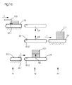
- FIG. 1b the transfer of a stack 101 from the device for forming stacks 21 to the device for banding 27 by means of a transport device 24 is shown in a snapshot in detail.
- a stack 101 formed in the lower level 23 of the apparatus 21 for forming stacks has just been transferred from the lower level 23 to the lower receiving level 26 of the transport device 24 by a transfer device 30.1 designed as a driving pin in the transport direction T.
- the lower receiving plane 26 is lifted by a lifting movement a2 until the lower receiving plane 26 at the level of the working plane 28 the banding device 27 is located.
- a stack 101 has just been transferred from a transfer device 30.2 designed as a conveyor belt to the working plane 28 of the device for banding 27 in the transporting direction T.
- the upper receiving plane 25 is also moved synchronously in the lifting direction a1 upwards.
- the upper receiving plane 25 is thereby raised to its upper position at the level of the upper level 22 of the device 21 for forming stacks (dotted).
- the finished stack 101 is transferred from the lower level 23 to the banding apparatus 27 by means of the transport 24, individual folded signatures 100 are placed on top of each other in the upper level 22 of the stack forming apparatus 21, thus forming a next stack educated.
- Fig. 1c likewise illustrates a transfer of stacks 101.
- the receiving planes 25, 26 of the transport device 24 are mechanically coupled together.
- the lifting movements a1 and a2 are coupled together.
- the one plane 28 of the banding device 27 is arranged in its vertical orientation centrally between the two planes 22, 23 of the device 21 for forming stacks.
- the vertical spacing of the two receiving planes 25, 26 from one another corresponds to the vertical distance between a respective plane 22, 23 of the stack forming device 21 and the one plane 28 of the banding device 27.
- FIGS. 2a and 2b each alternative embodiments of the display device according to the invention are shown. For a better overview, only the essential differences are shown.
- Feeder 20 and control unit 29 may, as in the FIGS. 1a and 1b be shown represented.
- Fig. 2a is located between the apparatus for forming stacks 21 and the device for banding 27, a transport device 24 with only one receiving plane 25.
- This receiving plane 25 is liftable a1 and can from its uppermost position where it rises to the level of the upper level 22 of the device Formation of stacks 21 past the working level 28 of the Banding device 27 is moved to its lowest position where it is at the level of the lower level 23 of the stacking device 21.
- Fig. 2a is located between the apparatus for forming stacks 21 and the device for banding 27, a transport device 24 with only one receiving plane 25.
- This receiving plane 25 is liftable a1 and can from its uppermost position where it rises to the level of the upper level 22 of the device Formation of stacks 21 past the working level 28
- the 2b embodiment shown also has a transport device 24 with only one receiving plane 25.
- the receiving plane 25 is in contrast to the embodiments described above not liftable but pivoting b.
- the pivot axis of the receiving plane 25 is located at the level of the working plane 28 of the device for banding.
- the pivoting range of the receiving plane 25 extends from a top-most position shown in phantom, where the receiving plane 25 can take stacks from the upper level 22 of the device 21 for forming stacks to a lower dash-dotted position shown where the receiving plane 25 in the lower level of the 23rd
- the device 21 formed to form stacks stack 101 can take.
- Fig. 3a is integrated into the device for banding 27 a lifting device.
- This can for example be designed as a lift.
- a banding unit of the banding device 27 can be vertically displaced by this lift, so that the banding unit can take stacks from both the top level 22 and the bottom level 23 of the stack forming apparatus 21. It is a structurally complex and complicated variant. Due to the vertical movement of the Banderolierü the performance of the delivery device 2 is additionally limited.
- Fig. 3b shows an expensive variant of a display device: to the upper level 22 of the device 21 for forming stacks is followed by a device for banding 27 and subsequently a device for removal with memory 3 at.
Landscapes
- Engineering & Computer Science (AREA)
- Mechanical Engineering (AREA)
- Basic Packing Technique (AREA)
- Auxiliary Devices For And Details Of Packaging Control (AREA)
Abstract
Description
- Die Erfindung betrifft eine Auslagevorrichtung für flache Produkte gemäß dem Oberbegriff von Anspruch 1 als auch ein Verfahren zum Betreiben einer Auslagevorrichtung gemäß Anspruch 10.
- In Druckweiterverarbeitungsmaschinen, wie beispielsweise Falzmaschinen, Sammelheftern, Trimmern und Dreischneidern schließt sich an die eigentliche Bearbeitungsstation eine Auslage für die bearbeiteten Produkte an. Dabei können die Produkte, d. h. gefalzte Signaturen, Broschuren oder Bücher entweder geschuppt ausgelegt werden oder eine bestimmte und vorgegebene Anzahl der Produkte wird auf einem Stapel abgelegt.
- Von Heidelberg wird unter dem Namen Twinstacker TSH eine vertikale Stapeleinheit mit zwei übereinander angeordneten Stapelebenen vertrieben. Durch die beiden Stapelebenen wird ein problemloser Nonstop-Betrieb der Stapeleinheit ermöglicht.
- Aus dem Stand der Technik sind weiterhin verschiedenartige Vorrichtungen zum Banderolieren bzw. Umreifen von Stapeln von Produkten bekannt. So zeigt beispielsweise die
DE OS 26 58 070 - Aus der
DE 196 15 009 A1 geht ein Kreuzleger mit Umreifungsvorrichtung hervor. Auf einer ersten Ebene in einem Schuppenstrom ankommende Druckerzeugnisse werden gestapelt, der Stapel vertikal nach unten in eine Umreifungsvorrichtung bewegt und dort mit einem Umreifungsband versehen. Eine Vorrichtung von ähnlichem Aufbau zeigt auch dieDE 37 05 169 C2 : Auf einem Förderband in einer ersten Ebene ankommende Druckerzeugnisse werden gesammelt und gestapelt. Der Stapel wird mittels einer Überführungseinrichtung vertikal nach unten zu einer Verpackungseinrichtung transportiert, wo der Stapel mit einer Banderole versehen wird. In der Ebene der Verpackungseinrichtung und sich an die Verpackungseinrichtung anschließend befindet sich ein Förderband zum Abtransport der banderolierten Stapel. - Aufgabe der vorliegenden Erfindung ist es, eine Auslagevorrichtung für flache Produkte zu schaffen, bei der auf zwei Ebenen gebildete Stapel an eine nachfolgende Vorrichtung zur Weiterverarbeitung, wie beispielsweise eine Vorrichtung zum Banderolieren, übergeben werden können.
- Gelöst wird diese Aufgabe durch eine Auslagevorrichtung für flache Produkte mit den kennzeichnenden Merkmalen von Anspruch 1 und durch ein Verfahren gemäß Anspruch 10.
- Die erfindungsgemäße Auslagevorrichtung für flache Produkte aus Papier, Pappe und dergleichen umfasst eine Vorrichtung zur Bildung von Stapeln aus den Produkten und nachfolgend eine Vorrichtung zur Weiterbearbeitung der Stapel. Die Vorrichtung zur Bildung von Stapeln besitzt mindestens zwei im wesentlichen horizontale Ebenen, in welchen die Stapel gebildet werden. Die Vorrichtung zur Weiterbearbeitung der Stapel besitzt nur eine im wesentlichen horizontale Ebene, in welcher die Stapel bearbeitet werden. In der Vorrichtung zur Weiterverarbeitung der Stapel werden die Stapel mit dem Fachmann geläufigen Mitteln in Transportrichtung weitertransportiert. Zwischen der Vorrichtung zur Bildung von Stapeln und der Vorrichtung zur Weiterverarbeitung der Stapel ist vorteilhafterweise eine Transporteinrichtung angebracht zum Transport der Stapel von der jeweiligen Ebene der Vorrichtung zur Bildung von Stapeln zu der einen Ebene der Vorrichtung zur Weiterverarbeitung der Stapel. Von der Vorrichtung zur Bildung von Stapeln zur Transporteinrichtung und von der Transporteinrichtung zur Vorrichtung zur Weiterverarbeitung der Stapel werden die Stapel jeweils durch eine Übergabeeinrichtung transportiert. Bei der Übergabeeinrichtung kann es sich beispielweise um horizontal bewegte Mitnehmer, bewegte Greifer, eine angetriebene Rollenbahn oder um angetriebene Förderbänder handeln.
- Die Erfindung betrifft auch eine Auslagevorrichtung für flache Produkte aus Papier, Pappe und dergleichen mit einer Vorrichtung zum Banderolieren. Bei den Produkten kann es sich insbesondere um Signaturen oder Broschuren handeln, welche von einer Weiterverarbeitungsmaschine, insbesondere einer Falzmaschine bzw. einem Sammelhefter an die Auslagevorrichtung übergeben werden. Die Auslagevorrichtung umfasst eine Zuführeinrichtung, nachfolgend eine Vorrichtung zur Bildung von Stapeln aus den Produkten und nachfolgend eine Vorrichtung zum Banderolieren der Stapel. Banderolieren meint damit das Versehen des Stapels mit einer Banderole bzw. das Umreifen des Stapels mit einem Umreifungsband. Die Vorrichtung zur Bildung von Stapeln weist mindestens zwei Ebenen auf, wobei in jeder Ebene Stapel gebildet werden. Die Vorrichtung zum Banderolieren weist eine Ebene auf, in welcher die Stapel banderoliert werden. In vorteilhafter Weise ist zwischen der Vorrichtung zur Bildung von Stapeln und der Vorrichtung zum Banderolieren eine Transporteinrichtung angebracht zum Transport der Stapel von der jeweiligen Ebene der Vorrichtung zur Bildung von Stapeln zu der einen Ebene der Vorrichtung zum Banderolieren. Die Transporteinrichtung ermöglicht damit das Zusammenführen des Materialflusses, d.h. das Zusammenführen der Stapel von zwei Ebenen auf eine Ebene. Bänder bzw. Ein- und Ausschubmittel können in dem Fachmann bekannter Weise elektromotorisch angetrieben sein. An die Vorrichtung zum Banderolieren kann sich eine Einrichtung zum Abtransport der Stapel anschließen, welche über eine Speicherstrecke verfügt. Vorteilhaft an einer derartigen Auslagevorrichtung ist, dass nur eine Vorrichtung zum Banderolieren benötigt wird und die Herstellungskosten der Auslagevorrichtung damit gering gehalten werden können. Durch eine entsprechende Ansteuerung der Transporteinrichtung können mit der Auslagevorrichtung flache Produkte mit einer hohen Taktfrequenz gestapelt, banderoliert und ausgelegt werden.
- In einer vorteilhaften Weiterbildung der Auslagevorrichtung sind die Vorrichtung zur Bildung von Stapeln, die Transporteinrichtung und die Vorrichtung zum Banderolieren mit einer Steuereinrichtung verbunden. Die Taktfrequenzen, mit denen die Vorrichtung zur Bildung von Stapeln, die Transporteinrichtung und die Vorrichtung zum Banderolieren betrieben werden, können durch die Steuereinrichtung in vorteilhafter Weise gesteuert und relativ zueinander synchronisiert werden.
- In einer ersten Ausführungsform der erfindungsgemäßen Auslagevorrichtung verfügt die Transporteinrichtung über eine hubbewegliche Aufnahmeebene. Die hubbewegliche Aufnahmeebene kann eine Hubbewegung zwischen einem oberen und einem unteren Umkehrpunkt ausführen. Die Aufnahmeebene kann dabei in dem Fachmann bekannter Weise elektromotorisch angetrieben werden. Der obere Umkehrpunkt liegt dabei auf Höhe der oberen Ebene der Vorrichtung zur Bildung von Stapeln, der untere Umkehrpunkt liegt auf Höhe der unteren Ebene der Vorrichtung zur Bildung von Stapeln. Die Ebene der Vorrichtung zum Banderolieren liegt zwischen dem oberen und dem unteren Umkehrpunkt oder auch bevorzugterweise auf der Ebene eines Umkehrpunktes.
- In einer zweiten Ausführungsform der erfindungsgemäßen Auslagevorrichtung verfügt die Transporteinrichtung über eine schwenkbare Aufnahmeebene. Die Schwenkachse der Aufnahmeebene befindet sich dabei auf Höhe der einen Ebene der Vorrichtung zum Banderolieren. Die Aufnahmeebene kann eine Schwenkbewegung so durchführen, dass das bewegte Ende der Aufnahmeebene sich in seinem höchsten Punkt auf Höhe der oberen Ebene der Vorrichtung zur Bildung von Stapeln und in seinem untersten Punkt auf Höhe der unteren Ebene der Vorrichtung zur Bildung von Stapeln liegt.
- In einer dritten besonders vorteilhaften Ausführungsform der erfindungsgemäßen Auslagevorrichtung verfügt die Transporteinrichtung über zwei hubbewegliche Aufnahmeebenen. Eine erste Aufnahmeebene ist der ersten Ebene der Vorrichtung zur Bildung von Stapeln zugeordnet, eine zweite Aufnahmeebene ist der zweiten Ebene der Vorrichtung zur Bildung von Stapeln zugeordnet. Eine jeweilige Aufnahmeebene hat dabei zwei vertikal verschiedene Endlagen, wobei die eine auf der Höhe einer Ebene der Vorrichtung zur Bildung von Stapeln und die andere Endlage auf der Höhe der einen Ebene der Vorrichtung zum Banderolieren ist. Die Aufnahmeebenen können dabei in dem Fachmann bekannter Weise elektromotorisch angetrieben werden. Dazu kann entweder ein Elektromotor mit entsprechendem Getriebe mit beiden Aufnahmeebenen gekoppelt sein oder einer jeweiligen Aufnahmeebene ist je ein Elektromotor zugeordnet.
- In einer besonders vorteilhaften Weiterbildung der erfindungsgemäßen Auslagevorrichtung sind die Hubbewegungen der zwei Aufnahmeebenen miteinander synchronisiert. Die Synchronisation kann dabei durch eine mechanische Kopplung der Aufnahmeebenen mit einem gemeinsamen Antrieb oder durch eine Steuereinrichtung zur Ansteuerung von zwei Antrieben erfolgen, wobei jeder Aufnahmeebene ein Antrieb zugeordnet ist.
Besonders vorteilhaft ist es, wenn die eine Ebene der Vorrichtung zur Weiterverarbeitung der Stapel in ihrer vertikalen Ausrichtung mittig zwischen den beiden Ebenen der Vorrichtung zur Bildung von Stapeln angeordnet ist und wenn der Abstand der zwei Aufnahmeebenen voneinander dem Abstand einer jeweiligen Ebene der Vorrichtung zur Bildung von Stapeln von der einen Ebene der Vorrichtung zur Weiterverarbeitung entspricht. Bei einer derartigen Ausführung kann zeitgleich ein Stapel von der Vorrichtung zur Bildung von Stapeln auf eine der Aufnahmeebenen und ein anderer Stapel von der anderen Aufnahmeebene an die eine Ebene der Vorrichtung zur Weiterverarbeitung der Stapel übergeben werden. - Die Erfindung betrifft auch ein Verfahren zum Betreiben einer Auslagevorrichtung mit einer Vorrichtung zur Bildung von Stapeln, einer Transporteinrichtung und einer Vorrichtung zum Banderolieren. Von einer Weiterverarbeitungsmaschine kommende flache Produkte werden in die Vorrichtung zur Bildung von Stapeln geleitet. Dort wird zuerst auf einer der beiden Ebenen ein Stapel gebildet; nach Fertigstellung des Stapels wird auf der zweiten Ebene ein Stapel gebildet. Sobald ein Stapel fertig gebildet wurde, wird dieser von der Ebene der Vorrichtung zur Bildung von Stapeln auf die zugeordnete Aufnahmeebene der Transporteinrichtung ausgeschoben bzw. weitertransportiert. Die Aufnahmeebene fährt nachfolgend bis auf die Höhe der einen Ebene der Vorrichtung zum Banderolieren, um den Stapel dort an die Vorrichtung zum Banderolieren weiterzugeben. Während ein fertig gebildeter Stapel von einer der Ebenen der Vorrichtung zur Bildung von Stapeln an die zugeordnete Aufnahmeebene der Transporteinrichtung weitergegeben wird, kann bereits zeitgleich ein anderer Stapel von der anderen Aufnahmeebene an die eine Ebene der Vorrichtung zum Banderolieren weitergegeben werden. Die Hubbewegungen der beiden Aufnahmeebenen sind also so miteinander synchronisiert, dass eine höchstmögliche Transportleistung der Transporteinrichtung sichergestellt ist. Dies wird in vorteilhafter Weise dadurch erreicht, dass während ein Stapel gebildet wird, ein anderer Stapel bereits an die Vorrichtung zum Banderolieren übergeben wird. Auch der Einsatz von zwei hubbeweglichen Aufnahmeebenen trägt zu einer hohen Transportleistung bei.
- Hinsichtlich weiterer Vorteile und vorteilhafter Ausgestaltungen der Erfindung wird auf die Unteransprüche sowie die Beschreibung eines Ausführungsbeispiels unter Bezugnahme auf die beiliegenden Zeichnungen verwiesen.
- Die Erfindung soll anhand eines Ausführungsbeispiels noch näher erläutert werden. Es zeigen in schematischer Darstellung
- Fig. 1a
- eine Übersichtsdarstellung der erfindungsgemäßen Auslagevorrichtung in einer ersten vorteilhaften Ausführungsform
- Fig. 1b
- die Übergabe eines Stapels von der Vorrichtung zur Bildung von Stapeln an die Vorrichtung zum Banderolieren mittels einer Transporteinrichtung
- Fig. 1c
- die Übergabe eines Stapels von der Vorrichtung zur Bildung von Stapeln an die Vorrichtung zum Banderolieren mittels einer Transporteinrichtung in einer anderen Ausführungsform
- Fig. 2a
- eine zweite Ausführungsform einer erfindungsgemäßen Auslagevorrichtung
- Fig. 2b
- eine dritte Ausführungsform einer erfindungsgemäßen Auslagevorrichtung
- Fig. 3a
- eine erste alternative Auslagevorrichtung
- Fig. 3b
- eine zweite alternative Auslagevorrichtung
- In
Fig. 1a ist eine besonders bevorzugte Ausführungsform der erfindungsgemäßen Auslagevorrichtung 2 dargestellt. Gefalzte Signaturen 100 werden von einer Weiterverarbeitungsmaschine 1, hier einer Falzmaschine, kommend zu einer Auslagevorrichtung 2 transportiert. An die Auslagevorrichtung 2 schließt sich eine Einrichtung 3 zum Abtransport mit Speicher an. Die von der Weiterverarbeitungsmaschine 1 kommenden gefalzten Signaturen 100 können von einer Zuführeinrichtung 20 entweder in die obere Ebene 22 der Vorrichtung 21 zur Bildung von Stapeln oder in die untere Ebene 23 der Vorrichtung 21 zur Bildung von Stapeln transportiert werden. Der Transportweg durch die Zuführeinrichtung 20 ist durch eine strich-punktierte Linie angedeutet. Die Zuführeinrichtung kann beispielsweise durch Transportbandpaare gebildet werden. Die Signaturen 100 werden zwischen den Transportbändern bis zum Ort ihrer Stapelbildung transportiert. In der Momentaufnahme vonFig. 1a werden die gefalzten Signaturen 100 in die untere Ebene 23 der Vorrichtung zur Bildung von Stapeln 21 geleitet und dort zu einem Stapel gestapelt. In der oberen Ebene 22 der Vorrichtung 21 zur Bildung von Stapeln befindet sich ein bereits fertig gebildeter Stapel 101. Der oberen Ebene 22 der Vorrichtung 21 zur Bildung von Stapeln ist eine obere Aufnahmeebene 25 der Transporteinrichtung 24 zugeordnet. Der unteren Ebene 23 der Vorrichtung zur Bildung von Stapeln 21 ist eine untere Aufnahmeebene 26 der Transporteinrichtung 24 zugeordnet. Auf der unteren Aufnahmeebene 26 befindet sich ein Stapel 101, welcher von der unteren Ebene 23 an die untere Aufnahmeebene 26 übergeben wurde. Von der oberen Aufnahmeebene 25 wurde ein Stapel 101 an die Arbeitsebene 28 der Vorrichtung zum Banderolieren 27 übergeben. Dieser Stapel 101 wird durch die Vorrichtung zum Banderolieren 27 transportiert und darin mit einer Banderole versehen. Der fertig banderolierte Stapel 102 wird von der Vorrichtung zum Banderolieren 27 übergeben an die Einrichtung zum Abtransport 3 und auf einer Speicherstrecke abgelegt. Wie inFig. 1a angedeutet, sind die Vorrichtung 21 zur Bildung von Stapeln, die Transporteinrichtung 24 und die Vorrichtung zum Banderolieren 27 mit einer Steuereinrichtung 29 verbunden. Die Steuereinrichtung 29 stimmt den Prozess der Stapelbildung in der Vorrichtung 21 zur Bildung von Stapeln, die Hubbewegungen der Aufnahmeebene 25, 26 der Transporteinrichtung 24 und den Banderolierprozess in der Vorrichtung zum Banderolieren 27 zeitlich aufeinander ab. - In
Fig. 1b ist die Übergabe eines Stapels 101 von der Vorrichtung zur Bildung von Stapeln 21 an die Vorrichtung zum Banderolieren 27 mittels einer Transporteinrichtung 24 in einer Momentaufnahme im Detail dargestellt. Ein in der unteren Ebene 23 der Vorrichtung 21 zur Bildung von Stapeln gebildeter Stapel 101 wurde soeben von einer als Mitnehmerstift ausgebildeten Übergabeeinrichtung 30.1 in Transportrichtung T von der unteren Ebene 23 an die untere Aufnahmeebene 26 der Transporteinrichtung 24 übergeben. In einem nächsten Schritt wird die untere Aufnahmeebene 26 durch eine Hubbewegung a2 angehoben werden bis sich die untere Aufnahmeebene 26 auf Höhe der Arbeitsebene 28 der Vorrichtung zum Banderolieren 27 befindet. Dort befindet sich im dargestellten Moment noch die obere Aufnahmeebene 25. Von dieser wurde soeben ein Stapel 101 von einer als Förderband ausgebildeten Übergabeeinrichtung 30.2 an die Arbeitsebene 28 der Vorrichtung zum Banderolieren 27 in Transportrichtung T übergeben. Damit die untere Aufnahmeebene 26 in ihre obere Position verfahren kann, wird die obere Aufnahmeebene 25 ebenfalls synchron in Hubbewegungsrichtung a1 nach oben bewegt. Die obere Aufnahmeebene 25 wird dabei in ihre obere Position auf Höhe der oberen Ebene 22 der Vorrichtung 21 zur Bildung von Stapeln (punktiert dargestellt) angehoben. Während der fertig gebildete Stapel 101 von der unteren Ebene 23 mittels der Transporteinrichtung 24 an die Vorrichtung zum Banderolieren 27 übergeben wird, werden in der oberen Ebene 22 der Vorrichtung 21 zur Bildung von Stapeln einzelne gefalzte Signaturen 100 aufeinander abgelegt und es wird so ein nächster Stapel gebildet. -
Fig. 1c veranschaulicht in gleicher Weise eine Übergabe von Stapeln 101. Im Gegensatz zur Darstellung ausFig. 1b sind in dieser Ausführungsform die Aufnahmeebenen 25, 26 der Transporteinrichtung 24 mechanisch miteinander gekoppelt. Damit sind auch die Hubbewegungen a1 und a2 miteinander gekoppelt.
Die eine Ebene 28 der Vorrichtung zum Banderolieren 27 ist in ihrer vertikalen Ausrichtung mittig zwischen den beiden Ebenen 22, 23 der Vorrichtung 21 zur Bildung von Stapeln angeordnet ist. Der vertikale Abstand der zwei Aufnahmeebenen 25, 26 voneinander entspricht dem vertikalen Abstand zwischen einer jeweiligen Ebenen 22, 23 der Vorrichtung 21 zur Bildung von Stapeln und der einen Ebene 28 der Vorrichtung zum Banderolieren 27. - In den
Figuren 2a und 2b sind jeweils alternative Ausführungsformen der erfindungsgemäßen Auslagevorrichtung dargestellt. Zur besseren Übersicht werden nur die wesentlichen Unterschiede dargestellt. Zuführeinrichtung 20 und Steuereinheit 29 können wie in denFiguren 1a und1b dargestellt ausgeführt sein. InFig. 2a befindet sich zwischen der Vorrichtung zur Bildung von Stapeln 21 und der Vorrichtung zum Banderolieren 27 eine Transporteinrichtung 24 mit nur einer Aufnahmeebene 25. Diese Aufnahmeebene 25 ist hubbeweglich a1 und kann von ihrer obersten Position, wo sie sich auf Höhe der oberen Ebene 22 der Vorrichtung zur Bildung von Stapeln 21 vorbei an der Arbeitsebene 28 der Vorrichtung zum Banderolieren 27 bis in ihre unterste Lage, wo sie sich auf Höhe der unteren Ebene 23 der Vorrichtung zur Bildung von Stapeln 21 befindet, bewegt werden. Die inFig. 2b dargestellte Ausführungsform weist ebenfalls eine Transporteinrichtung 24 mit nur einer Aufnahmeebene 25 auf. Die Aufnahmeebene 25 ist im Gegensatz zu den zuvor beschriebenen Ausführungsformen nicht hubbeweglich sondern schwenkbar b. Die Schwenkachse der Aufnahmeebene 25 befindet sich auf Höhe der Arbeitsebene 28 der Vorrichtung zum Banderolieren. Der Schwenkbereich der Aufnahmeebene 25 erstreckt sich von einer strichpunktiert dargestellten obersten Position, wo die Aufnahmeebene 25 Stapel von der oberen Ebene 22 der Vorrichtung 21 zur Bildung von Stapeln übernehmen kann bis zu einer unteren strichpunktiert dargestellten Position, wo die Aufnahmeebene 25 in der unteren Ebene 23 der Vorrichtung 21 zur Bildung von Stapeln gebildete Stapel 101 übernehmen kann. - In den
Figuren 3a und 3b sind mögliche weniger vorteilhafte Auslagevorrichtungen dargestellt.
InFig. 3a ist in die Vorrichtung zum Banderolieren 27 eine Hubeinrichtung integriert. Diese kann beispielsweise als ein Lift ausgeführt sein. Eine Banderoliereinheit der Vorrichtung zum Banderolieren 27 kann durch diesen Lift vertikal verschoben werden, so dass die Banderoliereinheit Stapel sowohl von der oberen Ebene 22 als auch von der unteren Ebene 23 der Vorrichtung 21 zur Bildung von Stapeln übernehmen kann. Dabei handelt es sich um eine konstruktionstechnisch aufwendige und komplizierte Variante. Durch die Vertikalbewegung der Banderoliereinheit wird zusätzlich die Leistung der Auslagevorrichtung 2 begrenzt.
Fig. 3b zeigt eine teure Variante einer Auslagevorrichtung: An die obere Ebene 22 der Vorrichtung 21 zur Bildung von Stapeln schließt sich eine Vorrichtung zum Banderolieren 27 und nachfolgend eine Einrichtung zum Abtransport mit Speicher 3 an. Auch an die untere Ebene 23 der Vorrichtung 21 zur Bildung von Stapeln schließt sich eine Vorrichtung zum Banderolieren 27 und eine Einrichtung zum Abtransport mit Speicher 3 an. Der Einsatz von zwei Vorrichtungen zum Banderolieren 27 und zwei Einrichtungen zum Abtransport mit Speicher 3 stellt eine kostenintensive Lösung dar und ist damit nachteilig. -
- 1
- Weiterverarbeitungsmaschine
- 2
- Auslagevorrichtung
- 3
- Einrichtung zum Abtransport mit Speicher
- 20
- Zuführeinrichtung
- 21
- Vorrichtung zur Bildung von Stapeln
- 22
- Obere Ebene der Vorrichtung zur Bildung von Stapeln
- 23
- Untere Ebene der Vorrichtung zur Bildung von Stapeln
- 24
- Transporteinrichtung
- 25
- Obere Aufnahmeebene der Transporteinrichtung
- 26
- Untere Aufnahmeebene der Transporteinrichtung
- 27
- Vorrichtung zum Banderolieren
- 28
- Arbeitsebene der Vorrichtung zum Banderolieren
- 29
- Steuereinrichtung
- 30.1
- Übergabeeinrichtung der Vorrichtung zur Stapelbildung
- 30.2
- Übergabeeinrichtung der Transporteinrichtung
- 100
- gefalzte Signatur
- 101
- Stapel von Signaturen
- 102
- Banderolierter Stapel von Signaturen
- a1
- Hubbewegung der oberen Aufnahmeebene
- a2
- Hubbewegung der unteren Aufnahmeebene
- b
- Schwenkbewegung der Aufnahmeebene
- T
- Transportrichtung
Claims (10)
- Auslagevorrichtung (2) für flache Produkte (100) aus Papier, Pappe und dergleichen, umfassend eine Vorrichtung (21) zur Bildung von Stapeln (101) aus den Produkten (100), sowie nachfolgend eine Vorrichtung zur Weiterbearbeitung (27) der Stapel (101),
dadurch gekennzeichnet,
dass die Vorrichtung (21) zur Bildung von Stapeln mindestens zwei horizontale Ebenen (22, 23) aufweist, in welchen die Stapel (101) gebildet werden, und dass die Vorrichtung zur Weiterbearbeitung (27) der Stapel (101) eine horizontale Ebene (28) aufweist, in welcher die Stapel (101) bearbeitet werden,
wobei zwischen der Vorrichtung (21) zur Bildung von Stapeln und der Vorrichtung zur Weiterbearbeitung (27) der Stapel eine Transporteinrichtung (24) angebracht ist, welche die Stapel (101) von der jeweiligen horizontalen Ebene (22, 23) der Vorrichtung (21) zur Bildung von Stapeln zu der einen horizontalen Ebene (28) der Vorrichtung zur Weiterverarbeitung (27) der Stapel transportiert, und
wobei die Transporteinrichtung (24) eine Übergabeeinrichtung (30.2) aufweist zur Übergabe von Stapel (101) an die Vorrichtung zur Weiterverarbeitung (27), und wobei die Vorrichtung (21) zur Bildung von Stapeln eine Übergabeeinrichtung (30.1) aufweist zur Übergabe von Stapeln (101) an die Transporteinrichtung (24). - Auslagevorrichtung (2) nach Anspruch 1
dadurch gekennzeichnet,
dass es sich bei den flachen Produkten (100) insbesondere um Signaturen oder Broschuren aus einer Weiterverarbeitungsmaschine (1) handelt, insbesondere einer Falzmaschine oder einem Sammelhefter, dass vor der Vorrichtung (21) zur Bildung von Stapeln (101) eine Zuführeinrichtung (20) zum Zuführen von Produkten (100) angeordnet ist und dass es sich bei der Vorrichtung zur Weiterverarbeitung (27) der Stapel um eine Vorrichtung zum Banderolieren (27) der Stapel (101) handelt. - Auslagevorrichtung nach einem der vorangehenden Ansprüche,
dadurch gekennzeichnet,
dass die Vorrichtung (21) zur Bildung von Stapeln, die Transporteinrichtung (24) und die Vorrichtung zur Weiterverarbeitung (27) mit einer Steuereinrichtung (29) verbunden sind. - Auslagevorrichtung nach einem der vorangehenden Ansprüche,
dadurch gekennzeichnet,
dass die Transporteinrichtung (24) über eine hubbewegliche horizontale Aufnahmeebene (25) verfügt. - Auslagevorrichtung nach einem der vorangehenden Ansprüche,
dadurch gekennzeichnet,
dass die Transporteinrichtung (24) über eine schwenkbare Aufnahmeebene (25) verfügt. - Auslagevorrichtung nach einem der vorangehenden Ansprüche,
dadurch gekennzeichnet,
dass die Transporteinrichtung (24) über zwei hubbewegliche horizontale Aufnahmeebenen (25, 26) verfügt. - Auslagevorrichtung nach Anspruch 6,
dadurch gekennzeichnet,
dass die Hubbewegungen (a1, a2) der zwei horizontalen Aufnahmeebenen (25, 26) miteinander synchronisiert sind. - Auslagevorrichtung nach Anspruch 7,
dadurch gekennzeichnet,
dass die Synchronisation durch eine mechanische Kopplung der horizontalen Aufnahmeebenen (25, 26) erfolgt. - Auslagevorrichtung nach einem der Ansprüche 6 bis 8,
dadurch gekennzeichnet,
dass die eine Ebene (28) der Vorrichtung zur Weiterverarbeitung (27) der Stapel in ihrer vertikalen Ausrichtung mittig zwischen den beiden Ebenen (22, 23) der Vorrichtung (21) zur Bildung von Stapeln angeordnet ist und dass der vertikale Abstand der zwei Aufnahmeebenen (25, 26) voneinander dem vertikalen Abstand zwischen einer jeweiligen Ebene (22, 23) der Vorrichtung (21) zur Bildung von Stapeln und der einen Ebene (28) der Vorrichtung zur Weiterverarbeitung (27) von Stapeln entspricht. - Verfahren zum Betreiben einer Auslagevorrichtung (2) nach Anspruch 3 und einem der Ansprüche 7 bis 9,
gekennzeichnet durch nachfolgende Schritte:a) Abwechselndes Bilden von Stapeln (101) auf den beiden horizontalen Ebenen (22, 23) der Vorrichtung (21) zur Bildung von Stapelnb) Weitergabe eines ersten gebildeten Stapels (101) von einer der horizontalen Ebenen (22, 23) der Vorrichtung (21) zur Bildung von Stapeln an eine der horizontalen Aufnahmeebenen (25, 26) der Transporteinrichtung (24) durch eine Übergabeeinrichtung (30.1)c) In etwa zeitgleiches Übergeben eines Stapels (101) von der anderen horizontalen Aufnahmeebene (26, 25) an die eine horizontale Ebene (28) der Vorrichtung zum Banderolieren (27) durch eine Übergabeeinrichtung (30.2),d) Hubbewegung (a1, a2) der beiden horizontalen Aufnahmeebenen (25, 26) wobei sich die Schritte a) bis d) wiederholen.
Applications Claiming Priority (1)
| Application Number | Priority Date | Filing Date | Title |
|---|---|---|---|
| DE102008034765A DE102008034765A1 (de) | 2008-07-25 | 2008-07-25 | Auslagevorrichtung für flache Produkte |
Publications (2)
| Publication Number | Publication Date |
|---|---|
| EP2147881A2 true EP2147881A2 (de) | 2010-01-27 |
| EP2147881A3 EP2147881A3 (de) | 2012-02-08 |
Family
ID=41217789
Family Applications (1)
| Application Number | Title | Priority Date | Filing Date |
|---|---|---|---|
| EP09164915A Withdrawn EP2147881A3 (de) | 2008-07-25 | 2009-07-08 | Auslagevorrichtung für flache Produkte |
Country Status (3)
| Country | Link |
|---|---|
| EP (1) | EP2147881A3 (de) |
| CN (1) | CN101633447B (de) |
| DE (1) | DE102008034765A1 (de) |
Cited By (1)
| Publication number | Priority date | Publication date | Assignee | Title |
|---|---|---|---|---|
| EP3530595A1 (de) * | 2018-02-27 | 2019-08-28 | ISHIDA CO., Ltd. | Packungssammelvorrichtung |
Families Citing this family (10)
| Publication number | Priority date | Publication date | Assignee | Title |
|---|---|---|---|---|
| DE102011082747B4 (de) * | 2011-09-15 | 2022-06-30 | Krones Aktiengesellschaft | Vorrichtung und Verfahren zum Beladen von Paletten |
| CN102367114B (zh) * | 2011-10-08 | 2013-11-06 | 张家港市玉龙科技板材有限公司 | 玻镁板生产线中的出板装置 |
| CN104692176A (zh) * | 2015-02-25 | 2015-06-10 | 昆山宝锦激光拼焊有限公司 | 一种堆垛自动切换落料线 |
| CN106276378B (zh) * | 2016-09-18 | 2019-01-29 | 广州科程自动化设备有限公司 | 自动错位堆叠机及其使用方法 |
| CN106364965B (zh) * | 2016-10-15 | 2018-10-19 | 广州明森科技股份有限公司 | 一种智能卡生产设备的卡片收集装置 |
| CN107839933A (zh) * | 2017-12-18 | 2018-03-27 | 苏州市锐翊电子科技有限公司 | 一种自动包装系统 |
| DE102020103398A1 (de) * | 2020-02-11 | 2021-08-12 | Heidelberger Druckmaschinen Aktiengesellschaft | Verfahren zum Bewegen eines Produktstapels mit einem Roboter |
| CN113399279A (zh) * | 2021-05-24 | 2021-09-17 | 广西壮象木业有限公司 | 一种胶合板木皮筛选装置 |
| CN114873341B (zh) * | 2022-07-13 | 2022-09-27 | 山东盈科杰数码科技有限公司 | 一种印刷连线裁切分本不停机换堆系统 |
| CN118753782A (zh) * | 2024-07-31 | 2024-10-11 | 中联重科股份有限公司 | 空中下料装置及空中输送设备 |
Citations (3)
| Publication number | Priority date | Publication date | Assignee | Title |
|---|---|---|---|---|
| DE2658070A1 (de) | 1976-12-22 | 1978-07-06 | Gremser Masch Franz | Eingabetisch fuer mehrere stapel von etiketten o.dgl. an einer maschine zum umschliessen mit einer banderole |
| DE3705169C2 (de) | 1987-02-18 | 1989-05-03 | Sesto 7000 Stuttgart De Palamides | |
| DE19615009A1 (de) | 1996-04-16 | 1997-10-23 | Smb Schwede Maschinenbau Gmbh | Kreuzleger mit Umreifungsvorrichtung |
Family Cites Families (9)
| Publication number | Priority date | Publication date | Assignee | Title |
|---|---|---|---|---|
| DE2330614A1 (de) * | 1973-06-15 | 1975-01-09 | Windmoeller & Hoelscher | Vorrichtung zum bilden v4n losen paketen vorbestimmter werkstueckzahl aus uebereianderliegenden flachen werkstuecken |
| DE2443131A1 (de) * | 1974-09-09 | 1976-03-25 | Bhs Bayerische Berg | Vorrichtung zum stapeln von bogen |
| DE3269420D1 (en) * | 1981-10-08 | 1986-04-03 | Hobema Maschf Hermann | Device for forming and delivering small packages consisting of several plain individual products of paper, cellulose wadding or the like |
| DE3140021A1 (de) * | 1981-10-08 | 1983-04-28 | Hobema Maschinenfabrik Hermann H. Raths GmbH & Co KG, 4000 Düsseldorf | Einrichtung zur bildung und angabe von paeckchen aus mehreren, flaechigen einzelerzeugnissen aus papier, zellstoffwatte od. dgl. |
| IT1265845B1 (it) * | 1993-02-15 | 1996-12-12 | Perini Fabio Spa | Dispositivo per il trasferimento di tovagliolini o prodotti analoghi dalla macchina di produzione a mezzi impilatori. |
| EP0686127B1 (de) * | 1993-02-27 | 1997-04-09 | Heidelberger Druckmaschinen Aktiengesellschaft | Einrichtung zur bildung einzelner bogenstapel |
| FI101954B1 (fi) * | 1996-09-27 | 1998-09-30 | Jomet Oy | Menetelmä ja laitteisto litteiden esineiden pakkaamiseksi |
| CN2611329Y (zh) * | 2003-01-22 | 2004-04-14 | 汕头市东和机械有限公司 | 文件夹制造机的自动收台 |
| DE102004056018A1 (de) * | 2004-11-16 | 2006-05-18 | Bielomatik Leuze Gmbh + Co.Kg | Fördereinrichtung für durch Blattlagen gebildete Stapel |
-
2008
- 2008-07-25 DE DE102008034765A patent/DE102008034765A1/de not_active Withdrawn
-
2009
- 2009-07-08 EP EP09164915A patent/EP2147881A3/de not_active Withdrawn
- 2009-07-24 CN CN2009101616486A patent/CN101633447B/zh not_active Expired - Fee Related
Patent Citations (3)
| Publication number | Priority date | Publication date | Assignee | Title |
|---|---|---|---|---|
| DE2658070A1 (de) | 1976-12-22 | 1978-07-06 | Gremser Masch Franz | Eingabetisch fuer mehrere stapel von etiketten o.dgl. an einer maschine zum umschliessen mit einer banderole |
| DE3705169C2 (de) | 1987-02-18 | 1989-05-03 | Sesto 7000 Stuttgart De Palamides | |
| DE19615009A1 (de) | 1996-04-16 | 1997-10-23 | Smb Schwede Maschinenbau Gmbh | Kreuzleger mit Umreifungsvorrichtung |
Cited By (2)
| Publication number | Priority date | Publication date | Assignee | Title |
|---|---|---|---|---|
| EP3530595A1 (de) * | 2018-02-27 | 2019-08-28 | ISHIDA CO., Ltd. | Packungssammelvorrichtung |
| US10689205B2 (en) | 2018-02-27 | 2020-06-23 | Ishida Co., Ltd. | Package accumulating device |
Also Published As
| Publication number | Publication date |
|---|---|
| CN101633447B (zh) | 2013-06-05 |
| CN101633447A (zh) | 2010-01-27 |
| DE102008034765A1 (de) | 2010-01-28 |
| EP2147881A3 (de) | 2012-02-08 |
Similar Documents
| Publication | Publication Date | Title |
|---|---|---|
| EP2147881A2 (de) | Auslagevorrichtung für flache Produkte | |
| EP2631083A2 (de) | Vorrichtung zum Zuführen von Buchblocks in den Einfuhrkanal einer Weiterverarbeitungseinrichtung | |
| EP3049241B1 (de) | Maschine und verfahren zum falten und kleben von zuschnitten für die herstellung von faltschachteln | |
| DE102007002154A1 (de) | Vorrichtung und Verfahren zum Ausrichten von Bogenstapel | |
| DE102008048287A1 (de) | Vorrichtung und Verfahren zum Falzen von Bogen | |
| DE102011013983A1 (de) | Ein Stapler, ein Stapelsystem oder eine Stapelbaugruppe und ein Verfahren zum Stapeln | |
| WO2017167421A1 (de) | Modulsystem zum umgang mit getränkebehältnissen und entsprechendes verfahren hierfür | |
| EP2602220B1 (de) | Einrichtung und Verfahren zum Zusammenstellen von flächigen Produkten, insbesondere von Druckereiprodukten | |
| EP1405809B1 (de) | Einrichtung zur Herstellung von Stapelpaketen | |
| DE102016212130A1 (de) | Etikettiermaschine und Verfahren zur Herstellung von Multipacks | |
| DE102012021268A1 (de) | Verfahren und Vorrichtung zur Bildung eines Hilfsstapels | |
| EP0514783B1 (de) | Vorrichtung zum Fördern von Papierbogenstapeln | |
| EP2165954B1 (de) | Bogenverarbeitungsmaschine und Verfahren zum Ablegen von Bogen | |
| EP3269670A1 (de) | Verfahren und vorrichtung zum bilden von werbemittelzusammenstellungen | |
| DE102007046777A1 (de) | Vorrichtung zum Aufstecken von Säcken auf einen Füllstutzen einer Packmaschine | |
| EP2520525B1 (de) | Verfahren zur Herstellung von Stangen aus Druckprodukten | |
| EP3527500A1 (de) | Verpackungsvorrichtung für artikel und verfahren zum betreiben einer zur handhabung flächiger verpackungszuschnitte ausgebildeten verpackungsvorrichtung | |
| EP1961660A1 (de) | Vorrichtung und Verfahren zur Verpackung von stapelbaren Gegenständen, insbesondere von Druckereierzeugnissen | |
| EP1593633B1 (de) | Vorrichtung zum Bilden von Stapeln aus Druckprodukten | |
| EP2119569B1 (de) | Sammelhefter mit variabler Kettenteilung | |
| DE10220550A1 (de) | Verfahren und Vorrichtung zur Weiterverarbeitung von Druckzwischenprodukten | |
| EP2361861A1 (de) | Verfahren und Vorrichtung zum automatischen Zuführen von einzelnen Blattstapeln aus einer Druckmaschine in eine Klebebindemaschine | |
| EP1302423B1 (de) | Modul zur temporären Lagerung von flachen Druckprodukten | |
| DE19507343A1 (de) | Verfahren sowie Vorrichtung zur automatischen Zuführung eines Zuschnitts | |
| EP1671884A1 (de) | Vorrichtung zum Bestücken von Flaschen in Kisten mit Kartonbrücken |
Legal Events
| Date | Code | Title | Description |
|---|---|---|---|
| PUAI | Public reference made under article 153(3) epc to a published international application that has entered the european phase |
Free format text: ORIGINAL CODE: 0009012 |
|
| AK | Designated contracting states |
Kind code of ref document: A2 Designated state(s): AT BE BG CH CY CZ DE DK EE ES FI FR GB GR HR HU IE IS IT LI LT LU LV MC MK MT NL NO PL PT RO SE SI SK SM TR |
|
| PUAL | Search report despatched |
Free format text: ORIGINAL CODE: 0009013 |
|
| AK | Designated contracting states |
Kind code of ref document: A3 Designated state(s): AT BE BG CH CY CZ DE DK EE ES FI FR GB GR HR HU IE IS IT LI LT LU LV MC MK MT NL NO PL PT RO SE SI SK SM TR |
|
| RIC1 | Information provided on ipc code assigned before grant |
Ipc: B65H 31/24 20060101AFI20120104BHEP Ipc: B65H 31/30 20060101ALI20120104BHEP Ipc: B65G 47/64 20060101ALI20120104BHEP |
|
| 17P | Request for examination filed |
Effective date: 20120808 |
|
| STAA | Information on the status of an ep patent application or granted ep patent |
Free format text: STATUS: THE APPLICATION IS DEEMED TO BE WITHDRAWN |
|
| 18D | Application deemed to be withdrawn |
Effective date: 20160202 |