EP2148015A1 - Armature sanitaire dotée d'un tuyau d'évacuation conducteur de lumière - Google Patents
Armature sanitaire dotée d'un tuyau d'évacuation conducteur de lumière Download PDFInfo
- Publication number
- EP2148015A1 EP2148015A1 EP08013083A EP08013083A EP2148015A1 EP 2148015 A1 EP2148015 A1 EP 2148015A1 EP 08013083 A EP08013083 A EP 08013083A EP 08013083 A EP08013083 A EP 08013083A EP 2148015 A1 EP2148015 A1 EP 2148015A1
- Authority
- EP
- European Patent Office
- Prior art keywords
- sanitary fitting
- fitting according
- water outlet
- pipe piece
- discharge pipe
- Prior art date
- Legal status (The legal status is an assumption and is not a legal conclusion. Google has not performed a legal analysis and makes no representation as to the accuracy of the status listed.)
- Granted
Links
- XLYOFNOQVPJJNP-UHFFFAOYSA-N water Substances O XLYOFNOQVPJJNP-UHFFFAOYSA-N 0.000 claims abstract description 50
- 239000000463 material Substances 0.000 claims abstract description 5
- 230000008878 coupling Effects 0.000 claims description 8
- 238000010168 coupling process Methods 0.000 claims description 8
- 238000005859 coupling reaction Methods 0.000 claims description 8
- 238000011144 upstream manufacturing Methods 0.000 claims description 6
- 238000007789 sealing Methods 0.000 description 13
- 238000004026 adhesive bonding Methods 0.000 description 3
- 239000011324 bead Substances 0.000 description 2
- 239000008234 soft water Substances 0.000 description 2
- 230000008719 thickening Effects 0.000 description 2
- 239000004952 Polyamide Substances 0.000 description 1
- 239000000853 adhesive Substances 0.000 description 1
- 230000001070 adhesive effect Effects 0.000 description 1
- 238000005253 cladding Methods 0.000 description 1
- 230000006835 compression Effects 0.000 description 1
- 238000007906 compression Methods 0.000 description 1
- 230000001419 dependent effect Effects 0.000 description 1
- 239000010794 food waste Substances 0.000 description 1
- 239000008233 hard water Substances 0.000 description 1
- 239000002184 metal Substances 0.000 description 1
- 230000003287 optical effect Effects 0.000 description 1
- 239000004033 plastic Substances 0.000 description 1
- 229920003023 plastic Polymers 0.000 description 1
- 229920003229 poly(methyl methacrylate) Polymers 0.000 description 1
- 229920002647 polyamide Polymers 0.000 description 1
- 239000004926 polymethyl methacrylate Substances 0.000 description 1
- 239000007921 spray Substances 0.000 description 1
- 238000003466 welding Methods 0.000 description 1
Images


Classifications
-
- E—FIXED CONSTRUCTIONS
- E03—WATER SUPPLY; SEWERAGE
- E03C—DOMESTIC PLUMBING INSTALLATIONS FOR FRESH WATER OR WASTE WATER; SINKS
- E03C1/00—Domestic plumbing installations for fresh water or waste water; Sinks
- E03C1/02—Plumbing installations for fresh water
- E03C1/04—Water-basin installations specially adapted to wash-basins or baths
- E03C1/0404—Constructional or functional features of the spout
-
- F—MECHANICAL ENGINEERING; LIGHTING; HEATING; WEAPONS; BLASTING
- F21—LIGHTING
- F21V—FUNCTIONAL FEATURES OR DETAILS OF LIGHTING DEVICES OR SYSTEMS THEREOF; STRUCTURAL COMBINATIONS OF LIGHTING DEVICES WITH OTHER ARTICLES, NOT OTHERWISE PROVIDED FOR
- F21V33/00—Structural combinations of lighting devices with other articles, not otherwise provided for
- F21V33/0004—Personal or domestic articles
- F21V33/004—Sanitary equipment, e.g. mirrors, showers, toilet seats or paper dispensers
-
- F—MECHANICAL ENGINEERING; LIGHTING; HEATING; WEAPONS; BLASTING
- F21—LIGHTING
- F21Y—INDEXING SCHEME ASSOCIATED WITH SUBCLASSES F21K, F21L, F21S and F21V, RELATING TO THE FORM OR THE KIND OF THE LIGHT SOURCES OR OF THE COLOUR OF THE LIGHT EMITTED
- F21Y2115/00—Light-generating elements of semiconductor light sources
- F21Y2115/10—Light-emitting diodes [LED]
Definitions
- the present invention relates to a sanitary fitting according to the preamble of patent claim 1.
- Such a sanitary fitting is from the EP 1 705 297 A known. It has a water-bearing spout, which is made of a translucent material. It has an exposed light exit surface at a downstream end and an entrance surface upstream thereof. The light from a light source enters the outflow tube at the coupling surface and from the light exit surface at the outflow pipe.
- the surroundings of the outflowing water and / or the outflowing water itself, depending on the design of the end face can be illuminated.
- the environment of the outflowing water it can be ensured that even in bad ambient lighting, an object to be cleaned is optimally illuminated.
- the outflow tube has a first outflow tube piece with the coupling-in surface for the light and a second outflow tube piece with the light-emitting surface.
- the two Ausflußrohr mixede are designed and arranged relative to each other, that the light pipe is ensured by the coupling surface to the light exit surface.
- the second outflow tube piece is rotatably mounted on the first outflow tube piece.
- this relative movement requires little space or space and, on the other hand, a uniform optical conductivity can be ensured in a simple manner independently of the relative position of the two outlet pipe pieces relative to one another.
- the first outflow tube piece has a wall with a passage and the second outflow tube piece has a first opening and a second opening.
- the first opening is in flow communication with the passage while in the second position, the second opening is flow connected with the passage.
- the first opening is arranged with a central water outlet and the second opening is arranged with one around the first water outlet second water outlet of the second Ausuzarohr Anlagens fluidly connected. This allows, preferably axisymmetric, produce different water jets.
- the first water outlet is provided with a jet regulator.
- a jet regulator This can be in the corresponding position of the second Aushnerohr institutionss produce a soft water jet. Jet regulators of this type are well known.
- the second water outlet has a number of nozzles.
- a wreath with respect to the soft water jet, can produce hard water jets.
- the sanitary fitting is a kitchen fitting in order to remove stubborn food residues from the crockery or cutlery.
- the sanitary fitting can also be a shower spray, which can be switched in a manner according to the invention between a soft and a hard jet of water.
- a sanitary fitting 12 may instead of the Wasserausmannkopfs in the Fig. 1-3 Sanitary fitting shown EP 1 705 297 A to step.
- the structure and operation of the sanitary fitting is expressly made to the disclosure of this EP document.
- the water outlet head is attached to a Ausziehschlauch 14 which passes through a guide tube of the sanitary fitting 12 through in a well-known manner and is connected to a control cartridge. In a known manner by means of this the flow as the temperature of the water flowing out of the water outlet head 10 is usually adjustable.
- the Ausziehschlauch 14 has a bendable, usually made of metal, outer jacket tube 16 and a running inside the jacket tube 16, usually made of plastic or rubber water hose 18. Between the jacket tube 16 and the water hose 18 extends an electrical line 20, preferably in the form of a multi-core stranded wire.
- a housing 22 of the Wasserausmannkopfs 10 is bell-shaped and adapted to the shape of a receptacle of the spout.
- the housing 22 is provided with a pin-like extension aid 24 projecting in the radial direction.
- the pull-out aid 24 for, in the flow direction S downstream, annular housing end face 26, the otherwise at least approximately a constant thickness having wall 28 of the housing 22 has a bead-like thickening 30. This is intended, together with the pull-out aid 24, when moving back the water outlet head 10 in the receptacle of the guide tube to engage in a guide slot of this guide tube and thereby set the rotational position of the Wasseraushnemannkopfs 10 with respect to the guide tube.
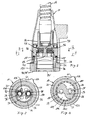
- the Wasserausmannkopf 10 has a water-conducting, translucent, photoconductive and with the Water hose 18 flow connected outflow pipe 32 on. It is for example made of acrylic glass or of another transparent or translucent material, such as a polyamide, in particular Grilamid®. In the exemplary embodiment shown, it consists of an upstream first outflow pipe piece 34 and a second outflow pipe piece 36 located downstream thereof. The second outflow pipe piece 36 is arranged around the first outflow pipe piece 34, which is fixed to the housing in the housing 22 and connected to it, for example, by adhesive bonding Longitudinal axis 38 of the Wasserausmannkopfs 10 between a first position 40 and a second position 42 rotatably supported back and forth. In the Fig. 1 - 4th is the second Ausflußrohr Biology 36 in the first position 40 and in the Fig. 5-7 in the second position 42.
- the first outflow tube piece 34 is formed in two parts, comprising a connection part 44 and a control part 46 arranged downstream thereof, these two parts being connected to one another at their common, annular contact surface 48, which preferably lies in a plane perpendicular to the longitudinal axis 38 are, for example by ultrasonic welding or gluing. Also, a one-piece embodiment of the first Ausflußrohr Anlagens 34 is conceivable.
- the connecting part 44 has a sleeve section 52 provided with an internal thread 50, from which a light coupling flange 54 projects in the radial direction towards the outside in the downstream end area.
- a connection piece 56 is threaded, which on the other hand in a known manner, for example as in the EP 1 705 297 A1 discloses, is firmly connected to the Ausziehschlauch 14.
- the fitting 56 has a radial passage through which the electrical lead 20 exits upstream of the sleeve portion 52.
- a sealing ring 62 is preferably in the form of a quadrant to prevent leakage of water supplied through the Ausziehschlauch 14.
- the Lichteinkopplungsflansch 54 has an upstream open, around the sleeve portion 52 extending around annular groove 64, the bottom of which forms a coupling surface 66 for the emitted light from a light source 68.
- a light source 68 a plurality of light emitting diodes (LED) 68 'are preferably used, which are arranged in the circumferential direction at regular intervals and whose light cone axis preferably extends at right angles through the coupling surface 66 and parallel to the longitudinal axis 38.
- LED light emitting diodes
- the light source emits 68 colored light.
- the attachment of the light guide plate 70 and the light source 68 am Connector 56 can be done for example by gluing or pouring.
- the control part 46 is cup-shaped, wherein the bottom, forming a perpendicular to the longitudinal axis 38 extending wall 72, abuts the connection part 44 and with this, as mentioned above, is firmly connected.
- the projecting from the wall 72 in the downstream direction jacket wall 74 is thick-walled and aligned in the axial direction with the coupling surface 66 to forward the coupled into the connector 56 light parallel to the longitudinal axis 38.
- the wall 72 has two with respect to the longitudinal axis 38 diametrically opposed passages 76, in each of which a sealing sleeve 78, in the axial direction displaceable but circumferentially sealing, is arranged.
- the sealing sleeve 78 is held by means of a helical spring designed as a compression spring 80, which is supported on the one hand on the wall 72 and on the other hand on the sealing sleeve 78 in sealing contact with the this side end face 82 of the second Aus pressrohr GmbHs 36.
- control part 46 and thus the first Ausflußrohr researching 36 is disposed in the interior of the housing 22 and fixedly connected thereto, for example by means of adhesive 84, wherein the free end of the jacket wall 74 is aligned with the housing end face 26.
- the second outflow tube piece 36 is also formed like a cup, wherein the bottom 86, the end face 82 forms, against which the sealing sleeves 78. Further, the bottom 86 with respect to the longitudinal axis 38 has two diametrically opposed first openings 88, which in the first position 40 of the first Ausflußrohr institutionss 34th are aligned with the passages 76 and flow-connected with these and thus the Ausziehschlauch 34. As in the Fig.
- the bottom 86 further has two with respect to the longitudinal axis 38 also diametrically opposite second openings 90, but offset by an angle which corresponds to the rotation angle between the first position 40 and the second position 42 of the second Ausuzarohr Anlagens 36 are arranged so that they are arranged offset in the first position 40 with respect to the passages 76 and are not fluidly connected thereto.
- the first openings 88 extend through the bottom 86 and open into a defined by the bottom 86 and the circumferential side wall 92 of the second Aus pressraum 94.
- a jet regulator 96 for example, a well-known Neoperl® jet regulator, for generating a by a central first water outlet 94 'emerging, "soft" water jet used.
- the second openings 90 are formed like a blind hole, wherein from them in the radial direction through the bottom 86 through to the radially lateral end of a flow gap 100 extends. In the second position 42, only the second openings 90 and thus the flow gaps 100 are flow-connected to the passages 76.
- the side wall 92 has a circumferential flow groove 102 which opens in the direction of the control part 46 and which communicates with the flow gaps 100 and from which a ring of nozzles 104 extends.
- Their nozzle outlet openings 106 are - forming a second water outlet 104 '- in the end face 98 and are arranged in the circumferential direction equidistant around the jet regulator 96 around.
- the nozzles 104 are intended to produce in the second position 42 of the second effluent tube 36 a ring of "hard” water jets as compared to the "soft” water jet.
- the second Aus pressrohr Trading 36 sleeve-shaped ring 108 from which engages in a circumferential sealing groove 110 of the wall 72 of the control part 46, in the radial direction outside of the passages 76.
- the ring 108 has a circumferential groove 112, in which a sealing ring 114 cooperating with the control part 46, for example an O-ring or a quadring, is inserted. This prevents water leakage from the passages 76 into the flow groove 102 when the second spout 36 is in the first position 40 and correspondingly from the flow groove 102 into the first openings 88 if the second spout 36 is in the second position 42 ,
- the end region 124 is provided with an inner step-like enlargement.
- control part 46 has a truncated cone-shaped deflection surface 130 in order to divert the water coming from the second openings 90 and the flow gaps 100 to the flow groove 102.
- the second outflow pipe piece 36 projects, in the flow direction S, over the housing 22, wherein the projecting end region of the side wall 92, in the radial direction towards the outside, is thickened and forms an exposed circumferential surface 132 on the circumference, which is preferably equidistant from the longitudinal axis 38 spaced as the radially outer surface of the thickening 30; see in particular FIG. 3, 4 . 6 and 7 ,
- the second effluent tube 36 has a radially projecting drive lug 134 in its end region protruding beyond the housing 22 - it may also be a plurality of catch lugs or one or more driving grooves - to facilitate turning of the second effluent tube 36 by hand ,
- the first position 40 and the second position 42 and thus the first openings 88 and second openings 90 are arranged offset relative to each other by approximately 60 °.
- the corresponding angle of rotation of the second Ausflußrohr matterss 36 with respect to the first Ausflußrohr forumss 34 is - as the Fig. 3 and 6 is removable - bounded by stop pins 136 of the second Ausurohr matterss 36, which cooperate with corresponding counter-attacks 138 of the control part 46.
- said angle can also be chosen smaller or larger, in particular 90 °.
- Light generated by the light source 68 enters the first effluent tube 34 at the light incident surface 66, is guided therethrough to the second effusion tube 36, which exits the light through the face 98 and the cladding surface 132 forming an exposed light exit surface 98 '.
- the end face 98 may be flat and formed at right angles to the longitudinal axis 38. However, it is also possible, as in the Fig. 1 . 2 and 5 shown to form the front side 98 convex. It should also be mentioned that there is a gap 140 between the housing end face 26 and the radially outwardly thickened end region of the second outflow pipe piece 36, to prevent damage. In this gap, a sliding ring may be arranged, as in Fig. 1 is recognizable.
- the exposed light exit surface 98 ' may also include only the front side 98, for example, when the lateral surface 132 does not allow the leakage of light; the lateral surface 132 may be treated or covered accordingly. It should also be mentioned that in the embodiment shown, light from the outflow pipe 32 is coupled into the water, in particular the "hard” water jets.
- passage 76 and the first and second openings 88, 90 in, for example, the longitudinal axis 38 concentric walls.
- inventive discharge pipe 32 on other types of sanitary fittings 12.
Landscapes
- Health & Medical Sciences (AREA)
- Engineering & Computer Science (AREA)
- Public Health (AREA)
- Life Sciences & Earth Sciences (AREA)
- Hydrology & Water Resources (AREA)
- Water Supply & Treatment (AREA)
- Epidemiology (AREA)
- General Engineering & Computer Science (AREA)
- Nozzles (AREA)
- Arrangement Of Elements, Cooling, Sealing, Or The Like Of Lighting Devices (AREA)
- Domestic Plumbing Installations (AREA)
Priority Applications (1)
| Application Number | Priority Date | Filing Date | Title |
|---|---|---|---|
| EP08013083.4A EP2148015B1 (fr) | 2008-07-21 | 2008-07-21 | Armature sanitaire dotée d'un tuyau d'évacuation conducteur de lumière |
Applications Claiming Priority (1)
| Application Number | Priority Date | Filing Date | Title |
|---|---|---|---|
| EP08013083.4A EP2148015B1 (fr) | 2008-07-21 | 2008-07-21 | Armature sanitaire dotée d'un tuyau d'évacuation conducteur de lumière |
Publications (3)
| Publication Number | Publication Date |
|---|---|
| EP2148015A1 true EP2148015A1 (fr) | 2010-01-27 |
| EP2148015A8 EP2148015A8 (fr) | 2010-03-31 |
| EP2148015B1 EP2148015B1 (fr) | 2013-08-21 |
Family
ID=40011169
Family Applications (1)
| Application Number | Title | Priority Date | Filing Date |
|---|---|---|---|
| EP08013083.4A Not-in-force EP2148015B1 (fr) | 2008-07-21 | 2008-07-21 | Armature sanitaire dotée d'un tuyau d'évacuation conducteur de lumière |
Country Status (1)
| Country | Link |
|---|---|
| EP (1) | EP2148015B1 (fr) |
Cited By (2)
| Publication number | Priority date | Publication date | Assignee | Title |
|---|---|---|---|---|
| EP2549024A1 (fr) * | 2011-07-18 | 2013-01-23 | P.G.I. Parigi Group International S.p.A. | Tuyau flexible pour appareils sanitaires destiné à être utilisé avec des dispositifs d'éclairage |
| DE102017202670A1 (de) * | 2017-02-20 | 2018-08-23 | Siemens Aktiengesellschaft | Transluzente Armatur |
Families Citing this family (1)
| Publication number | Priority date | Publication date | Assignee | Title |
|---|---|---|---|---|
| US11603987B2 (en) | 2020-08-31 | 2023-03-14 | Kraus Usa Plumbing Llc | Lighting system for fixtures and appliances |
Citations (3)
| Publication number | Priority date | Publication date | Assignee | Title |
|---|---|---|---|---|
| DE19654359C1 (de) | 1996-12-24 | 1998-08-20 | Gunter Veigel | Wasserauslaufarmatur |
| WO2004063478A1 (fr) | 2003-01-08 | 2004-07-29 | Youngsung Industrial Co., Ltd. | Appareil de tete utilise pour une conduite d'adduction capable de purifier l'eau |
| EP1705297A1 (fr) | 2005-03-11 | 2006-09-27 | Kwc Ag | Armature sanitaire avec tuyau d'écoulement gidant la lumière |
-
2008
- 2008-07-21 EP EP08013083.4A patent/EP2148015B1/fr not_active Not-in-force
Patent Citations (3)
| Publication number | Priority date | Publication date | Assignee | Title |
|---|---|---|---|---|
| DE19654359C1 (de) | 1996-12-24 | 1998-08-20 | Gunter Veigel | Wasserauslaufarmatur |
| WO2004063478A1 (fr) | 2003-01-08 | 2004-07-29 | Youngsung Industrial Co., Ltd. | Appareil de tete utilise pour une conduite d'adduction capable de purifier l'eau |
| EP1705297A1 (fr) | 2005-03-11 | 2006-09-27 | Kwc Ag | Armature sanitaire avec tuyau d'écoulement gidant la lumière |
Cited By (2)
| Publication number | Priority date | Publication date | Assignee | Title |
|---|---|---|---|---|
| EP2549024A1 (fr) * | 2011-07-18 | 2013-01-23 | P.G.I. Parigi Group International S.p.A. | Tuyau flexible pour appareils sanitaires destiné à être utilisé avec des dispositifs d'éclairage |
| DE102017202670A1 (de) * | 2017-02-20 | 2018-08-23 | Siemens Aktiengesellschaft | Transluzente Armatur |
Also Published As
| Publication number | Publication date |
|---|---|
| EP2148015B1 (fr) | 2013-08-21 |
| EP2148015A8 (fr) | 2010-03-31 |
Similar Documents
| Publication | Publication Date | Title |
|---|---|---|
| EP1162638B1 (fr) | Système d'illumination d'un bouton de manoeuvre d'un dispositif d'entrée de données par transparence | |
| EP2964843B1 (fr) | Régulateur de jet avec connecteur de tuyau | |
| EP1705297B1 (fr) | Armature sanitaire avec tuyau d'écoulement gidant la lumière | |
| EP2172274B1 (fr) | Pomme de douche convertible | |
| EP0294606B1 (fr) | Appareil pour vaporiser une peinture liquide | |
| EP2172273B1 (fr) | Pomme dotée d'un élément de maintien et d'une pomme de douche amovibles | |
| DE29521612U1 (de) | Umlenkventil für Duschsprühvorrichtungen | |
| EP2211249A2 (fr) | Dispositif de commande pour un appareil électrique et écran de commande | |
| DE10257783B3 (de) | Düsenanordnung für ein Hochdruckreinigungsgerät | |
| WO2006029680A1 (fr) | Lance de nettoyage | |
| CH663890A5 (de) | Zahnaerztliches handstueck. | |
| WO2020109593A1 (fr) | Arrangement de nettoyage avec un piston alternatif | |
| EP2148015B1 (fr) | Armature sanitaire dotée d'un tuyau d'évacuation conducteur de lumière | |
| EP1391182A2 (fr) | Piece à main avec un élément luminescent à son extrémité avant | |
| WO2009010133A1 (fr) | Feu d'arrêt comportant au moins une buse de liquide de lavage | |
| EP2016231B1 (fr) | Système sanitaire comportant une douchette et une unité de charge | |
| EP0770202A1 (fr) | Dispositif d'affichage eclaire et aiguille eclairee | |
| EP2700758B1 (fr) | Poignée de baignoire dotée d'un trop-plein intégré et dispositif d'écoulement et de trop-plein doté d'une telle poignée | |
| EP3348718B1 (fr) | Dispositif d'actionnement pour une soupape d'un dispositif d'écoulement pour un bassin | |
| EP2016232B1 (fr) | Douchette sanitaire | |
| EP3727958A1 (fr) | Dispositif formant balai d'essuie-glace | |
| EP1004712A2 (fr) | Rosette de couverture pour la zone de connection d'une robinetterie murale sanitaire | |
| EP0638366A1 (fr) | Tube à jet pour dispositif de nettoyage à haute pression | |
| DE102015210620B3 (de) | Betätigungselement mit Beleuchtungseinrichtung und Paneel mit einem derartigen Element | |
| DE102007011181B4 (de) | Sanitärarmatur |
Legal Events
| Date | Code | Title | Description |
|---|---|---|---|
| PUAI | Public reference made under article 153(3) epc to a published international application that has entered the european phase |
Free format text: ORIGINAL CODE: 0009012 |
|
| AK | Designated contracting states |
Kind code of ref document: A1 Designated state(s): AT BE BG CH CY CZ DE DK EE ES FI FR GB GR HR HU IE IS IT LI LT LU LV MC MT NL NO PL PT RO SE SI SK TR |
|
| AX | Request for extension of the european patent |
Extension state: AL BA MK RS |
|
| RIN1 | Information on inventor provided before grant (corrected) |
Inventor name: BRUNNER, STEFAN Inventor name: LEHNER, MICHAEL Inventor name: BAUMANN, DANIEL Inventor name: GAUTSCHI, CHRISTIAN |
|
| 17P | Request for examination filed |
Effective date: 20100310 |
|
| EL | Fr: translation of claims filed | ||
| 17Q | First examination report despatched |
Effective date: 20100429 |
|
| AKX | Designation fees paid |
Designated state(s): AT CH DE FR IT LI |
|
| GRAP | Despatch of communication of intention to grant a patent |
Free format text: ORIGINAL CODE: EPIDOSNIGR1 |
|
| GRAS | Grant fee paid |
Free format text: ORIGINAL CODE: EPIDOSNIGR3 |
|
| GRAA | (expected) grant |
Free format text: ORIGINAL CODE: 0009210 |
|
| AK | Designated contracting states |
Kind code of ref document: B1 Designated state(s): AT CH DE FR IT LI |
|
| REG | Reference to a national code |
Ref country code: CH Ref legal event code: EP Ref country code: CH Ref legal event code: NV Representative=s name: PATENTANWAELTE SCHAAD, BALASS, MENZL AND PARTN, CH |
|
| REG | Reference to a national code |
Ref country code: AT Ref legal event code: REF Ref document number: 628210 Country of ref document: AT Kind code of ref document: T Effective date: 20130915 |
|
| REG | Reference to a national code |
Ref country code: DE Ref legal event code: R096 Ref document number: 502008010512 Country of ref document: DE Effective date: 20131017 |
|
| REG | Reference to a national code |
Ref country code: DE Ref legal event code: R097 Ref document number: 502008010512 Country of ref document: DE |
|
| PLBE | No opposition filed within time limit |
Free format text: ORIGINAL CODE: 0009261 |
|
| STAA | Information on the status of an ep patent application or granted ep patent |
Free format text: STATUS: NO OPPOSITION FILED WITHIN TIME LIMIT |
|
| 26N | No opposition filed |
Effective date: 20140522 |
|
| REG | Reference to a national code |
Ref country code: DE Ref legal event code: R097 Ref document number: 502008010512 Country of ref document: DE Effective date: 20140522 |
|
| REG | Reference to a national code |
Ref country code: DE Ref legal event code: R082 Ref document number: 502008010512 Country of ref document: DE Representative=s name: LEMCKE, BROMMER & PARTNER, PATENTANWAELTE PART, DE Ref country code: DE Ref legal event code: R081 Ref document number: 502008010512 Country of ref document: DE Owner name: FRANKE WATER SYSTEMS AG, ZWEIGNIEDERLASSUNG UN, CH Free format text: FORMER OWNER: KWC AG, UNTERKULM, CH |
|
| REG | Reference to a national code |
Ref country code: FR Ref legal event code: PLFP Year of fee payment: 9 |
|
| PGFP | Annual fee paid to national office [announced via postgrant information from national office to epo] |
Ref country code: IT Payment date: 20160721 Year of fee payment: 9 Ref country code: DE Payment date: 20160719 Year of fee payment: 9 Ref country code: CH Payment date: 20160726 Year of fee payment: 9 |
|
| PGFP | Annual fee paid to national office [announced via postgrant information from national office to epo] |
Ref country code: AT Payment date: 20160720 Year of fee payment: 9 Ref country code: FR Payment date: 20160722 Year of fee payment: 9 |
|
| REG | Reference to a national code |
Ref country code: DE Ref legal event code: R119 Ref document number: 502008010512 Country of ref document: DE |
|
| REG | Reference to a national code |
Ref country code: CH Ref legal event code: PL |
|
| REG | Reference to a national code |
Ref country code: AT Ref legal event code: MM01 Ref document number: 628210 Country of ref document: AT Kind code of ref document: T Effective date: 20170721 |
|
| REG | Reference to a national code |
Ref country code: FR Ref legal event code: ST Effective date: 20180330 |
|
| PG25 | Lapsed in a contracting state [announced via postgrant information from national office to epo] |
Ref country code: CH Free format text: LAPSE BECAUSE OF NON-PAYMENT OF DUE FEES Effective date: 20170731 Ref country code: LI Free format text: LAPSE BECAUSE OF NON-PAYMENT OF DUE FEES Effective date: 20170731 Ref country code: DE Free format text: LAPSE BECAUSE OF NON-PAYMENT OF DUE FEES Effective date: 20180201 |
|
| PG25 | Lapsed in a contracting state [announced via postgrant information from national office to epo] |
Ref country code: FR Free format text: LAPSE BECAUSE OF NON-PAYMENT OF DUE FEES Effective date: 20170731 Ref country code: AT Free format text: LAPSE BECAUSE OF NON-PAYMENT OF DUE FEES Effective date: 20170721 |
|
| PG25 | Lapsed in a contracting state [announced via postgrant information from national office to epo] |
Ref country code: IT Free format text: LAPSE BECAUSE OF NON-PAYMENT OF DUE FEES Effective date: 20170721 |