EP2148178A1 - Procédé de transmission de données numérique bidirectionnel - Google Patents
Procédé de transmission de données numérique bidirectionnel Download PDFInfo
- Publication number
- EP2148178A1 EP2148178A1 EP08013238A EP08013238A EP2148178A1 EP 2148178 A1 EP2148178 A1 EP 2148178A1 EP 08013238 A EP08013238 A EP 08013238A EP 08013238 A EP08013238 A EP 08013238A EP 2148178 A1 EP2148178 A1 EP 2148178A1
- Authority
- EP
- European Patent Office
- Prior art keywords
- data
- measuring system
- control unit
- transmitted
- position measuring
- Prior art date
- Legal status (The legal status is an assumption and is not a legal conclusion. Google has not performed a legal analysis and makes no representation as to the accuracy of the status listed.)
- Granted
Links
Images




Classifications
-
- H—ELECTRICITY
- H04—ELECTRIC COMMUNICATION TECHNIQUE
- H04L—TRANSMISSION OF DIGITAL INFORMATION, e.g. TELEGRAPHIC COMMUNICATION
- H04L5/00—Arrangements affording multiple use of the transmission path
- H04L5/14—Two-way operation using the same type of signal, i.e. duplex
- H04L5/1469—Two-way operation using the same type of signal, i.e. duplex using time-sharing
- H04L5/1484—Two-way operation using the same type of signal, i.e. duplex using time-sharing operating bytewise
-
- G—PHYSICS
- G01—MEASURING; TESTING
- G01D—MEASURING NOT SPECIALLY ADAPTED FOR A SPECIFIC VARIABLE; ARRANGEMENTS FOR MEASURING TWO OR MORE VARIABLES NOT COVERED IN A SINGLE OTHER SUBCLASS; TARIFF METERING APPARATUS; MEASURING OR TESTING NOT OTHERWISE PROVIDED FOR
- G01D5/00—Mechanical means for transferring the output of a sensing member; Means for converting the output of a sensing member to another variable where the form or nature of the sensing member does not constrain the means for converting; Transducers not specially adapted for a specific variable
- G01D5/12—Mechanical means for transferring the output of a sensing member; Means for converting the output of a sensing member to another variable where the form or nature of the sensing member does not constrain the means for converting; Transducers not specially adapted for a specific variable using electric or magnetic means
Definitions
- the invention relates to a method for digital, bidirectional data transmission according to the preamble of patent claim 1.
- the invention relates in particular to a method for digital, bidirectional data transmission between a control unit and a position measuring system.
- the EP 0 171 579 A1 discloses an arrangement for the serial transmission of the measured values of at least one transducer, in which the parallel pending measurements are stored in a parallel-serial shift register and serially transmitted in time with a clock pulse sequence generated by a processing unit receiving the measurements.
- the disadvantage here is that a data transfer takes place only from the transducer to the processing unit.
- the DE 100 30 358 A1 discloses a method for serial data transmission between a position measuring system and a processing unit, in which position data and further data are transmitted from the position measuring system as digital data words to the processing unit.
- position data and further data are transmitted from the position measuring system as digital data words to the processing unit.
- current position data is transmitted from the position measuring system to the processing unit.
- further data is always transmitted to the position data.
- a position request command is transmitted to the position measuring system by the processing unit for requesting position data, to which subsequently further data are likewise always transmitted whose processing is non-time critical.
- the transfer of data from The processing unit to the position measuring system takes place on a different data line than the transmission of data from the position measuring system to the processing unit.
- a concrete position request command is required to transmit position data, whereby the time between the transmission of two position data can be comparatively long.
- the DE 10 2006 022 284 A1 discloses a method for digital bidirectional data transmission between a control unit and a position measuring system based on the transmission of frames of a predetermined bit length.
- each frame there is at least a first bit length for the transmission of data from the control unit to the position measuring system and at least a second bit length for the transmission of data from the Position measuring system provided to the control unit.
- a time slot is provided in the frame, in which neither data are transmitted from the control unit to the position measuring system nor from the position measuring system to the control unit and in which a trigger pulse is transmitted from the control unit to the position measuring system, which triggers a position data recording in the position measuring system.
- the object of the invention is to make a method for digital, bidirectional data transmission between a control unit and a position measuring system more effective.
- the transmission of the clock signal for synchronizing the control unit and the position measuring system within the first bit length from the control unit to the position measuring system has the advantage that no additional data line is required for transmitting the clock signal.
- the number of data lines between the control unit and the position measuring system can thus be reduced.
- the transmission of at least one, preferably a plurality of additional position data request signals between two successive trigger pulses and the subsequent further position data acquisition and transmission of the recorded position data has the advantage that the position data signal may be present much more frequently at the control unit and thus at shorter intervals information about the position data of the position measuring system. It is essential that the trigger pulses are specified externally, while the additional data request signals are generated internally in the control unit and therefore are in particular independent of the external trigger pulse.
- a plurality of position request signals are periodically transmitted from the control unit to the position measuring system, wherein particularly preferably the time between two trigger pulses is an integer multiple of the time between two position request signals.
- the time between two trigger pulses is an integer multiple of the time between two position request signals.
- the data transmission takes place via two lines, in particular to two supply lines arranged between the control unit and the position measuring system.
- the data transmission over two lines has the advantage that it is significantly less susceptible to interference than the data transmission only on one line and in particular according to a preferred embodiment of the invention enables a differential data transmission.
- the data transmission in particular to two supply lines arranged between the control unit and the position measuring system, in particular power and voltage supply lines, makes it possible to reduce the number of lines arranged between the control unit and the position measuring system to two and thus to keep the costs for the arrangement low.
- the method is preferably designed such that a DC voltage compensation is ensured in the data transmission, which is achieved in particular by using an 8B / 10B code.
- This type of data transmission also has the advantage that the number of bit changes is sufficiently high and in this way in addition a reliable transmission of the clock signal for synchronization of the control unit and the position measuring unit on the same data lines, which are also used for data transmission is guaranteed.
- the position data or other data to be transmitted are transmitted as difference data of the first or second order.
- difference data is the change, d. H. the difference of the absolute value to the last absolute value.
- difference data of second order the change, i. H. to understand the difference to the last difference value or last change.
- the data to be transmitted is additionally transmitted as absolute data.
- the absolute data which is recalculated to the difference data, is compared with the exact absolute data and, if a difference occurs, is discarded and the exact absolute value is used as the basis for the further calculations.
- a check of the data transmission for errors is provided, in particular by means of a CRC (Cyclic Redundancy Check) method.
- CRC Cyclic Redundancy Check
- the data transmission takes place redundantly, in particular to provide a secure method for data transmission between the control unit and the position measuring system, thus providing a safe sensor in terms of machine safety, which means that the sensor meets the relevant standards EN954 or EN61508 , which deal with the machine safety, must suffice.
- the redundant data transmission can be ensured, for example, by a two-channel structure of independent transmission of the position data, by test structures or self-checking structures or it must be ensured in other ways even with errors occurring reliable operation and be possible, the error independently to recognize.
- further data in particular measurement data from further measuring systems, whose data acquisition can also be triggered in particular by the trigger signal, transmitted in order to avoid the use of additional data lines, in particular for other external sensors in this way.
- the other measuring systems can, for example, as Acceleration sensors, vibration sensors, torque sensors or temperature sensors may be formed.
- the individual data to be transmitted are divided into data segments, which in particular are transmitted segment by segment according to the individual position data request signals can.
- the system according to the invention has a control unit and a position measuring system, between which bidirectional data are transmitted, wherein the transmission of the data proceeds according to a method according to one of the preceding claims.
- the position measuring units are particularly preferably designed as rotary encoders.
- two supply lines are arranged between the control unit and the position measuring system, which are used simultaneously for data transmission, in order to reduce the number of data lines between the control unit and the position measuring system and in particular to limit two.
- the data lines, which in particular simultaneously represent the supply lines are integrated in a motor cable.
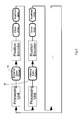
- FIG. 1 shows a schematic representation of a system with a control unit 10 and a position measuring system 20, between which two data lines 31, 32 data can be transmitted in both directions based on the transmission of frames of a predetermined bit length.
- at least one first bit length is provided in each frame for the transmission of data from the control unit 10 to the position measuring system 20 and at least one second bit length for the transmission of data from the position measuring system 20 to the control unit.
- the two data lines 31, 32 can simultaneously represent the supply lines from the control unit 10 to the position measuring system 20, in this way only two data lines between the control unit 10 and the position measuring system 20 (also see FIG. 7 ).
- the data lines 31, 32 are preferably twisted together to reduce interference.
- the data is transmitted in particular in such a way that a DC voltage compensation is ensured. This is done in particular by using an 8B / 10B code.
- the position measuring system 20 has a communication unit 22 for communication with the control unit 10, a data recording unit 24 for detecting the position data of, for example, a rotary encoder and a memory unit 26, wherein in the memory unit 26, for example, internal data of the position measuring system and / or the encoder are stored.
- the position measuring system can be connected to further measuring systems 28, which are designed for example as acceleration sensors, vibration sensors, torque sensors or temperature sensors and can provide additional data and information about the state of the position measuring system 20, in particular the rotary encoder, which in addition to the position data on the data lines 31, 32 can be transmitted to the control unit.
- the acceleration sensor or the vibration sensor for example, the acceleration or the vibration of the rotary encoder or the motor system, with which the rotary encoder is connected, can be determined.
- the torque of the shaft of the rotary encoder or the motor can be determined.
- the temperature sensor can monitor the temperature of the encoder or motor. All sensors may preferably detect deviations from predetermined setpoint values, in order to be able to check the system for occurring errors.
- the control unit 10 is supplied with an external trigger pulse 40, which triggers the position data recording in the position measuring system 20.
- the trigger pulse 40 must be transmitted as jitter-free as possible from the control unit 10 to the position measuring system 20. This is preferably done in such a way that a time slot is provided in the frame, in which neither data are transmitted from the control unit 10 to the position measuring system 20 nor from the position measuring system 20 to the control unit 10 and in which the trigger pulse 40 directly from the control unit 10 to the Position measuring system 20 is transmitted. In this way, time delays which may occur by transmitting the trigger pulse in the predetermined clock of the control unit 10 can be avoided.
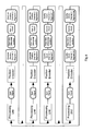
- FIG. 2 shows a data transmission protocol, which in particular represents a frame length.
- the trigger pulse 40 External Sync Signal
- the position encoder 20 Position Encoder
- This trigger pulse 40 triggers a position data recording in the position measuring system 20.
- non-time critical data can be transmitted from the position measuring system 20 to the control unit 10.
- the non-time-critical data can be, for example, measurement data of part of the previously described further measurement systems 28, for example temperature data, or system information about the position measurement system 20.
- the position data is time-critical data (real-time data), which must be transmitted in time with the control unit 10 and the position measuring system 20. Further time-critical data may be data of part of the other measuring systems 28 described above, for example data of an acceleration sensor, a vibration sensor or a torque sensor.
- FIG. 2 how out FIG. 2 can be seen, only one trigger pulse 40 is transmitted per frame. However, since the time interval between two trigger pulses 40 can be comparatively large, the position data are too infrequent for some applications. Therefore, the time interval between two trigger pulses 40 is determined in the control unit 10 at the beginning of the data transmission.
- the control unit 10 then internally generates position request signals 42 (Internal Sync Signal) which are periodically transmitted from the control unit 10 to the position measuring system 20 between two successive trigger pulses 40.
- position request signals 42 On each of the position request signals 42 takes place again a position data acquisition and a transmission of the position data from the position measuring system 20 to the control unit 10.
- the position data are significantly more frequently at the control unit 10, whereby a more accurate detection of the position data is possible.
- the position data taking can be transmitted again non-time critical data.
- only one or several additional position data request signals 42 can be transmitted between two successive trigger pulses 40.
- FIG. 3 shows a further data transmission protocol with multiple frames, each one line of the schematic data transmission protocol is a frame and for clarity the additional position data request signals according to FIG. 2 were omitted with the subsequently transmitted data.
- the position data and possibly also the other time-critical and non-time critical data are transmitted as difference data (real-time differential position), wherein the one-time transmission of the absolute position data in the transmission of the next position data value only the change, ie Difference to which the previous value and not the absolute value is transferred.
- difference data real-time differential position
- the number of required bits can be reduced from 40 to 24, and if second order differential data is transmitted, the number of necessary bits can even be reduced to 11.
- the position data is again transmitted as absolute data (absolute position) to the absolute position data recalculated from the difference data with the absolute position data actually present to be able to compare and, if applicable, to the correct ones, in fact to be able to use available absolute position data.
- the distance between the trigger pulses 40 and the position data request signals 42 is too short to completely transfer, for example, the absolute position data or other data to be transmitted in addition to the difference data.
- it's like in FIG. 3 it is possible, preferably possible, to divide the corresponding data to be transmitted into a certain number n of data segments and to transmit only one data segment between the trigger pulses 40 and the position data request signals 42, wherein after transmission of the n data segments the absolute position data (absolute position segment 1 to n) the complete data can be reconstructed.
- the absolute position data it is also possible to carry out a check for errors in each frame, for example by means of a CRC (cyclic redundancy check) method.
- the data to be transmitted within the frame can also be transmitted as absolute data, as differential data or partly as data segments (quality check segment 1 to m).
- quality check can also be transmitted as absolute data, as differential data or partly as data segments (quality check segment 1 to m).
- one data segment can be transmitted from the absolute position data and from the absolute data of the error check before each position data transmitted as difference data.
- the data and data segments to be transmitted can be transmitted both following the trigger pulse and following the additional position data request signals, depending on the manner in which the position data acquisition was triggered.
- the position measuring system 20 has a second channel for independent position data taking of second position data (absolute position channel 2), wherein the position data of the second channel is used either only as absolute position data, in particular as in FIG FIG. 4 represented in data segments (absolute position Channel 2 segment 1 to 2), or transmitted as difference data with additional transmission of the absolute position data after transmission of some difference data.
- the data transmission in the second channel is also checked for errors (quality check channel 2), in particular by means of a CRC method, whereby the data to be transmitted is also displayed again as a whole or in data segments (quality check channel 2 segment 1 to m).
- quality check channel 2 segment 1 to m quality check channel 2 segment 1 to m.
- FIG. 5 shows another data transmission protocol with multiple frames, each one line of the schematic data transmission protocol represents a frame and for clarity the additional position data request signals according to FIG. 2 were omitted with the subsequently transmitted data.
- this data transmission protocol in addition to the position data transmitted as difference data, the additional absolute position data transmitted in data segments and the data of the CRC method, further data (external data) are transmitted, for example, from the previously described further measurement systems into data segments (external data segments 1 to 1) ,
- a trigger pulse and at least one position data request signal are transmitted in each frame, wherein the recorded position data are transmitted either as absolute position data or as difference data both to the trigger pulse and to the position data request signal.
- the others on the basis of FIGS. 3 to 5 described transmissions of the different data can be transmitted individually or arbitrarily combined with each other.
- FIG. 6 shows a circuit arrangement for the transmission of data between the control unit 10 and the position measuring system 20 with four lines, of which two lines form the data lines 31, 32 and via two further lines 35, 36, the current and voltage supply of the position measuring system 20 takes place.
- the data lines 31, 32 are in particular twisted, with the data to be transmitted being transmitted, in particular, differentially on the data lines 31, 32.
- a transmitting and receiving circuit 55 is arranged, which is followed by a bus termination 51 for filtering common mode noise.
- This will be a very robust Achieved circuit, which can be arranged in particular in the immediate vicinity of the motor of the position measuring system, without significant interference occur.
- a transformer 50 for galvanic isolation as well as for coupling and decoupling the data onto the data lines 31, 32 is arranged on the side of the position measuring system 20.
- FIG. 7 shows a circuit arrangement for the transmission of data between the control unit 10 and the position measuring system 20 with only two lines, which on the one hand form the data lines 31, 32 and which simultaneously serve as supply lines of the position measuring system 20.
- the data to be transmitted are coupled in each case on the side of the control unit 10 and on the side of the position measuring system 20 via a respective transformer 50.
- a bus termination 52 is arranged between the transmitting and receiving circuit 55 of the control unit 10 and the associated transformer 50 and between the transmitting and receiving circuit 55 of the position measuring system 20 and the associated transformer 50.
- a protection circuit 53 in particular a suppressor diode, is added.
- the supply voltage of the position measuring system 20 is applied or removed via the input or output coupler circuit 54 to the data lines 31, 32.
Landscapes
- Engineering & Computer Science (AREA)
- Signal Processing (AREA)
- Computer Networks & Wireless Communication (AREA)
- Physics & Mathematics (AREA)
- General Physics & Mathematics (AREA)
- Arrangements For Transmission Of Measured Signals (AREA)
- Transmission And Conversion Of Sensor Element Output (AREA)
- Selective Calling Equipment (AREA)
- Synchronisation In Digital Transmission Systems (AREA)
Priority Applications (4)
| Application Number | Priority Date | Filing Date | Title |
|---|---|---|---|
| ES08013238T ES2385173T3 (es) | 2008-07-23 | 2008-07-23 | Procedimiento para la transmisión de datos digital bidireccional |
| EP08013238A EP2148178B1 (fr) | 2008-07-23 | 2008-07-23 | Procédé de transmission de données numérique bidirectionnel |
| AT08013238T ATE554368T1 (de) | 2008-07-23 | 2008-07-23 | Verfahren zur digitalen, bidirektionalen datenübertragung |
| US12/458,695 US8135977B2 (en) | 2008-07-23 | 2009-07-21 | Process for digital, bidirectional data transmission |
Applications Claiming Priority (1)
| Application Number | Priority Date | Filing Date | Title |
|---|---|---|---|
| EP08013238A EP2148178B1 (fr) | 2008-07-23 | 2008-07-23 | Procédé de transmission de données numérique bidirectionnel |
Publications (2)
| Publication Number | Publication Date |
|---|---|
| EP2148178A1 true EP2148178A1 (fr) | 2010-01-27 |
| EP2148178B1 EP2148178B1 (fr) | 2012-04-18 |
Family
ID=40086453
Family Applications (1)
| Application Number | Title | Priority Date | Filing Date |
|---|---|---|---|
| EP08013238A Active EP2148178B1 (fr) | 2008-07-23 | 2008-07-23 | Procédé de transmission de données numérique bidirectionnel |
Country Status (4)
| Country | Link |
|---|---|
| US (1) | US8135977B2 (fr) |
| EP (1) | EP2148178B1 (fr) |
| AT (1) | ATE554368T1 (fr) |
| ES (1) | ES2385173T3 (fr) |
Cited By (4)
| Publication number | Priority date | Publication date | Assignee | Title |
|---|---|---|---|---|
| EP2804059A3 (fr) * | 2013-05-15 | 2015-05-06 | Dr. Johannes Heidenhain GmbH | Procédé de transmission de données entre un dispositif de mesure de position et une unité de traitement associée ainsi que dispositif de mesure de position correspondant |
| US20190036731A1 (en) * | 2017-07-31 | 2019-01-31 | Hengstler Gmbh | Data transmission method between a rotary encoder and a motor control device or an evualation unit |
| DE102018102788A1 (de) | 2018-02-08 | 2019-08-08 | Hengstler Gmbh | Verfahren zur Datenübertragung zwischen einem Encoder und einer Motor- und/oder Aktor-Kontrolleinheit über einen unsicheren Kanal |
| EP4044560B1 (fr) | 2021-02-16 | 2025-07-02 | Hengstler GmbH | Moyeu de capteur |
Families Citing this family (9)
| Publication number | Priority date | Publication date | Assignee | Title |
|---|---|---|---|---|
| EP2341445B1 (fr) * | 2009-12-30 | 2017-09-06 | Intel Deutschland GmbH | Procédé pour le transfert de données à haute vitesse |
| EP2372312B1 (fr) * | 2010-03-31 | 2013-11-20 | SICK STEGMANN GmbH | Agencement de feedback et procédé de feedback destinés au réglage d'un servomoteur |
| DE102010024524A1 (de) * | 2010-06-21 | 2011-12-22 | Robert Bosch Gmbh | Verfahren zum Ansteuern wenigstens einer mittels eines Gebersignals an eine Bearbeitungsmaschine angekoppelten Bearbeitungseinrichtung |
| DE102013005237A1 (de) | 2013-03-27 | 2014-10-02 | Sew-Eurodrive Gmbh & Co Kg | Antriebssystem und Verfahren zum Betrieben eines Antriebssystems |
| CN104486386A (zh) * | 2014-12-02 | 2015-04-01 | 科世达(上海)管理有限公司 | 车用传感器标定方法和系统 |
| DE102017117090A1 (de) | 2017-07-28 | 2019-01-31 | Hengstler Gmbh | Verfahren zur Ansteuerung eines gebremsten Servomotors oder eines Linearantriebes mit einer Kontrolleinheit |
| DE102017216666A1 (de) * | 2017-09-20 | 2019-03-21 | Dr. Johannes Heidenhain Gmbh | Positionsmesseinrichtung und Verfahren zum Betreiben einer Positionsmesseinrichtung |
| US11211851B2 (en) | 2019-05-10 | 2021-12-28 | Rockwell Automation Technologies, Inc. | System and method for providing safe limited force producing power in a motor |
| TWI863996B (zh) * | 2019-05-24 | 2024-12-01 | 瑞典商埃迪爾都公司 | 用於無損資料壓縮和解壓縮的方法、裝置、和電腦程式產品 |
Citations (8)
| Publication number | Priority date | Publication date | Assignee | Title |
|---|---|---|---|---|
| EP0100386A1 (fr) * | 1982-08-02 | 1984-02-15 | Firecom Inc. | Système de détection et de commande à distance |
| US4486739A (en) | 1982-06-30 | 1984-12-04 | International Business Machines Corporation | Byte oriented DC balanced (0,4) 8B/10B partitioned block transmission code |
| EP0171579A1 (fr) | 1984-07-13 | 1986-02-19 | Max Stegmann Gmbh Uhren- und Elektroapparatefabrik | Dispositif pour transmettre en séries les valeurs mesurées d'au moins un transducteur |
| US5428603A (en) * | 1993-05-17 | 1995-06-27 | Hughes Aircraft Company | Synchronous time division multiple access interrogate-respond data communication network |
| DE10030358A1 (de) | 2000-06-21 | 2002-01-03 | Heidenhain Gmbh Dr Johannes | Verfahren und Vorrichtung zur seriellen Datenübertragung zwischen einem Positionsmesssystem und einer Verarbeitungseinheit |
| EP1434382A1 (fr) * | 2001-10-02 | 2004-06-30 | Hitachi, Ltd. | Appareil de transfert de donnees en serie |
| DE102004025388A1 (de) * | 2004-05-17 | 2005-12-15 | Balluff Gmbh | Verfahren und Vorrichtung zur Ermittlung der Position und/oder einer oder mehrerer Bewegungsgrößen eines Gegenstandes |
| DE102006022284A1 (de) | 2006-05-11 | 2007-11-15 | Sick Stegmann Gmbh | Verfahren zur Synchronisation einer bidirektionalen Übertragung von Daten |
Family Cites Families (3)
| Publication number | Priority date | Publication date | Assignee | Title |
|---|---|---|---|---|
| US6621304B2 (en) * | 2001-11-06 | 2003-09-16 | Infineon Technologies Aktiengesellschaft | Clocking and synchronization circuitry |
| EP1450534A4 (fr) * | 2001-11-22 | 2010-11-10 | Panasonic Corp | Systeme, appareil, procede d'emission de donnees, et recepteur de donnees |
| US7154994B2 (en) * | 2004-04-14 | 2006-12-26 | Varian Medical Systems, Inc. | Synchronization of x-ray data acquisition |
-
2008
- 2008-07-23 ES ES08013238T patent/ES2385173T3/es active Active
- 2008-07-23 EP EP08013238A patent/EP2148178B1/fr active Active
- 2008-07-23 AT AT08013238T patent/ATE554368T1/de active
-
2009
- 2009-07-21 US US12/458,695 patent/US8135977B2/en active Active
Patent Citations (8)
| Publication number | Priority date | Publication date | Assignee | Title |
|---|---|---|---|---|
| US4486739A (en) | 1982-06-30 | 1984-12-04 | International Business Machines Corporation | Byte oriented DC balanced (0,4) 8B/10B partitioned block transmission code |
| EP0100386A1 (fr) * | 1982-08-02 | 1984-02-15 | Firecom Inc. | Système de détection et de commande à distance |
| EP0171579A1 (fr) | 1984-07-13 | 1986-02-19 | Max Stegmann Gmbh Uhren- und Elektroapparatefabrik | Dispositif pour transmettre en séries les valeurs mesurées d'au moins un transducteur |
| US5428603A (en) * | 1993-05-17 | 1995-06-27 | Hughes Aircraft Company | Synchronous time division multiple access interrogate-respond data communication network |
| DE10030358A1 (de) | 2000-06-21 | 2002-01-03 | Heidenhain Gmbh Dr Johannes | Verfahren und Vorrichtung zur seriellen Datenübertragung zwischen einem Positionsmesssystem und einer Verarbeitungseinheit |
| EP1434382A1 (fr) * | 2001-10-02 | 2004-06-30 | Hitachi, Ltd. | Appareil de transfert de donnees en serie |
| DE102004025388A1 (de) * | 2004-05-17 | 2005-12-15 | Balluff Gmbh | Verfahren und Vorrichtung zur Ermittlung der Position und/oder einer oder mehrerer Bewegungsgrößen eines Gegenstandes |
| DE102006022284A1 (de) | 2006-05-11 | 2007-11-15 | Sick Stegmann Gmbh | Verfahren zur Synchronisation einer bidirektionalen Übertragung von Daten |
Cited By (8)
| Publication number | Priority date | Publication date | Assignee | Title |
|---|---|---|---|---|
| EP2804059A3 (fr) * | 2013-05-15 | 2015-05-06 | Dr. Johannes Heidenhain GmbH | Procédé de transmission de données entre un dispositif de mesure de position et une unité de traitement associée ainsi que dispositif de mesure de position correspondant |
| US9213499B2 (en) | 2013-05-15 | 2015-12-15 | Dr. Johannes Heidenhain Gmbh | Method for transferring data between a position-measuring device and an associated processing unit and position-measuring device therefor |
| US20190036731A1 (en) * | 2017-07-31 | 2019-01-31 | Hengstler Gmbh | Data transmission method between a rotary encoder and a motor control device or an evualation unit |
| CN109327365A (zh) * | 2017-07-31 | 2019-02-12 | 亨斯特勒有限公司 | 在转角传感器与发动机控制装置或分析单元之间的数据传递方法 |
| US11005681B2 (en) * | 2017-07-31 | 2021-05-11 | Hengstler Gmbh | Data transmission method between a primary master and primary slave via a bus line and between sub-slaves via the same bus line |
| CN109327365B (zh) * | 2017-07-31 | 2021-11-16 | 亨斯特勒有限公司 | 在转角传感器与发动机控制装置或分析单元之间的数据传递方法 |
| DE102018102788A1 (de) | 2018-02-08 | 2019-08-08 | Hengstler Gmbh | Verfahren zur Datenübertragung zwischen einem Encoder und einer Motor- und/oder Aktor-Kontrolleinheit über einen unsicheren Kanal |
| EP4044560B1 (fr) | 2021-02-16 | 2025-07-02 | Hengstler GmbH | Moyeu de capteur |
Also Published As
| Publication number | Publication date |
|---|---|
| ATE554368T1 (de) | 2012-05-15 |
| ES2385173T3 (es) | 2012-07-19 |
| US20100023791A1 (en) | 2010-01-28 |
| EP2148178B1 (fr) | 2012-04-18 |
| US8135977B2 (en) | 2012-03-13 |
Similar Documents
| Publication | Publication Date | Title |
|---|---|---|
| EP2148178B1 (fr) | Procédé de transmission de données numérique bidirectionnel | |
| EP2751956B1 (fr) | Procédé et équipement pour la vérification du fonctionnement correct d'une transmission série de données | |
| EP2759096B1 (fr) | Procédé et dispositif de couplage d'un premier capteur avec au moins un deuxième capteur | |
| EP2098930B1 (fr) | Système de surveillance pour un dispositif d'entraînement | |
| EP2000866B1 (fr) | Dispositif de surveillance destiné à la reconnaissance d'un adressage incorrect d'un esclave dans un système de bus de terrain | |
| EP2289201B1 (fr) | Dispositif et procédé de transmission de données en série entre un appareil de mesure de position et une unité de commande | |
| EP2023092B1 (fr) | Appareil de mesure de position et procédé de transmission d'une information de mouvement | |
| EP2853862B1 (fr) | Dispositif de mesure de position et procédé de vérification d'un signal de cadence de travail | |
| EP1802019A1 (fr) | Détection d'erreurs lors de la transmission de données | |
| EP4029185A1 (fr) | Dispositif et procédé pour la transmission synchrone de données en série | |
| EP2742642B1 (fr) | Dispositif de transmission de valeurs de mesure | |
| EP2475968B1 (fr) | Réseau de détecteurs et procédé pour faire fonctionner ce dernier | |
| DE102009060321A1 (de) | Steuersystem für Baumaschinen und Verfahren zum Betrieb des Steuersystems | |
| EP1886434B1 (fr) | Procede pour transmettre des donnees pour commander un systeme de transmission de courant continu haute tension | |
| DE102019132278A1 (de) | Sensorvorrichtung, Steuerung sowie Verfahren zur Kommunikation zwischen einer Sensorvorrichtung und einer Steuerung | |
| WO2012072121A1 (fr) | Dispositif et procédé de transfert d'articles en forme de barre de l'industrie de traitement du tabac | |
| EP2394400A1 (fr) | Unité de traitement d'état configurable pour systèmes de capteurs/actionneurs | |
| EP1596517B1 (fr) | Procédé de transmission sur un seul canal de données fournies sous forme redondante | |
| DE102005039450B4 (de) | Verfahren und Netzwerk zur synchronen Bearbeitung und Bereitstellung von Daten | |
| EP3091685B1 (fr) | Dispositif et procede destines a la preparation de trames de donnees en serie | |
| DE19517437A1 (de) | Verfahren und Vorrichtung zum Übertragen inkrementaler Winkel- oder Weginformationen | |
| DE3605359C2 (de) | Rechnersystem mit mehreren Rechnern | |
| WO2020200996A1 (fr) | Système de transmission de données pour véhicule utilitaire et procédé associé | |
| EP3524939B1 (fr) | Procédé de transmission de données entre un codeur et une unité de commande de moteur et / ou d'actionneur par l'intermédiaire d'un canal non sécurisé | |
| DE102013204891B4 (de) | Verfahren zur Rekonstruktion von Messdaten |
Legal Events
| Date | Code | Title | Description |
|---|---|---|---|
| PUAI | Public reference made under article 153(3) epc to a published international application that has entered the european phase |
Free format text: ORIGINAL CODE: 0009012 |
|
| AK | Designated contracting states |
Kind code of ref document: A1 Designated state(s): AT BE BG CH CY CZ DE DK EE ES FI FR GB GR HR HU IE IS IT LI LT LU LV MC MT NL NO PL PT RO SE SI SK TR |
|
| AX | Request for extension of the european patent |
Extension state: AL BA MK RS |
|
| 17P | Request for examination filed |
Effective date: 20100415 |
|
| AKX | Designation fees paid |
Designated state(s): AT BE BG CH CY CZ DE DK EE ES FI FR GB GR HR HU IE IS IT LI LT LU LV MC MT NL NO PL PT RO SE SI SK TR |
|
| GRAP | Despatch of communication of intention to grant a patent |
Free format text: ORIGINAL CODE: EPIDOSNIGR1 |
|
| GRAS | Grant fee paid |
Free format text: ORIGINAL CODE: EPIDOSNIGR3 |
|
| GRAA | (expected) grant |
Free format text: ORIGINAL CODE: 0009210 |
|
| AK | Designated contracting states |
Kind code of ref document: B1 Designated state(s): AT BE BG CH CY CZ DE DK EE ES FI FR GB GR HR HU IE IS IT LI LT LU LV MC MT NL NO PL PT RO SE SI SK TR |
|
| REG | Reference to a national code |
Ref country code: GB Ref legal event code: FG4D Free format text: NOT ENGLISH |
|
| REG | Reference to a national code |
Ref country code: CH Ref legal event code: EP |
|
| REG | Reference to a national code |
Ref country code: IE Ref legal event code: FG4D Free format text: LANGUAGE OF EP DOCUMENT: GERMAN |
|
| REG | Reference to a national code |
Ref country code: AT Ref legal event code: REF Ref document number: 554368 Country of ref document: AT Kind code of ref document: T Effective date: 20120515 |
|
| REG | Reference to a national code |
Ref country code: DE Ref legal event code: R096 Ref document number: 502008006946 Country of ref document: DE Effective date: 20120614 |
|
| REG | Reference to a national code |
Ref country code: ES Ref legal event code: FG2A Ref document number: 2385173 Country of ref document: ES Kind code of ref document: T3 Effective date: 20120719 |
|
| REG | Reference to a national code |
Ref country code: NL Ref legal event code: VDEP Effective date: 20120418 |
|
| LTIE | Lt: invalidation of european patent or patent extension |
Effective date: 20120418 |
|
| PG25 | Lapsed in a contracting state [announced via postgrant information from national office to epo] |
Ref country code: NO Free format text: LAPSE BECAUSE OF FAILURE TO SUBMIT A TRANSLATION OF THE DESCRIPTION OR TO PAY THE FEE WITHIN THE PRESCRIBED TIME-LIMIT Effective date: 20120718 Ref country code: IS Free format text: LAPSE BECAUSE OF FAILURE TO SUBMIT A TRANSLATION OF THE DESCRIPTION OR TO PAY THE FEE WITHIN THE PRESCRIBED TIME-LIMIT Effective date: 20120818 Ref country code: SE Free format text: LAPSE BECAUSE OF FAILURE TO SUBMIT A TRANSLATION OF THE DESCRIPTION OR TO PAY THE FEE WITHIN THE PRESCRIBED TIME-LIMIT Effective date: 20120418 Ref country code: PL Free format text: LAPSE BECAUSE OF FAILURE TO SUBMIT A TRANSLATION OF THE DESCRIPTION OR TO PAY THE FEE WITHIN THE PRESCRIBED TIME-LIMIT Effective date: 20120418 Ref country code: LT Free format text: LAPSE BECAUSE OF FAILURE TO SUBMIT A TRANSLATION OF THE DESCRIPTION OR TO PAY THE FEE WITHIN THE PRESCRIBED TIME-LIMIT Effective date: 20120418 Ref country code: CY Free format text: LAPSE BECAUSE OF FAILURE TO SUBMIT A TRANSLATION OF THE DESCRIPTION OR TO PAY THE FEE WITHIN THE PRESCRIBED TIME-LIMIT Effective date: 20120418 Ref country code: FI Free format text: LAPSE BECAUSE OF FAILURE TO SUBMIT A TRANSLATION OF THE DESCRIPTION OR TO PAY THE FEE WITHIN THE PRESCRIBED TIME-LIMIT Effective date: 20120418 |
|
| PG25 | Lapsed in a contracting state [announced via postgrant information from national office to epo] |
Ref country code: LV Free format text: LAPSE BECAUSE OF FAILURE TO SUBMIT A TRANSLATION OF THE DESCRIPTION OR TO PAY THE FEE WITHIN THE PRESCRIBED TIME-LIMIT Effective date: 20120418 Ref country code: PT Free format text: LAPSE BECAUSE OF FAILURE TO SUBMIT A TRANSLATION OF THE DESCRIPTION OR TO PAY THE FEE WITHIN THE PRESCRIBED TIME-LIMIT Effective date: 20120820 Ref country code: GR Free format text: LAPSE BECAUSE OF FAILURE TO SUBMIT A TRANSLATION OF THE DESCRIPTION OR TO PAY THE FEE WITHIN THE PRESCRIBED TIME-LIMIT Effective date: 20120719 Ref country code: HR Free format text: LAPSE BECAUSE OF FAILURE TO SUBMIT A TRANSLATION OF THE DESCRIPTION OR TO PAY THE FEE WITHIN THE PRESCRIBED TIME-LIMIT Effective date: 20120418 Ref country code: SI Free format text: LAPSE BECAUSE OF FAILURE TO SUBMIT A TRANSLATION OF THE DESCRIPTION OR TO PAY THE FEE WITHIN THE PRESCRIBED TIME-LIMIT Effective date: 20120418 |
|
| PG25 | Lapsed in a contracting state [announced via postgrant information from national office to epo] |
Ref country code: CZ Free format text: LAPSE BECAUSE OF FAILURE TO SUBMIT A TRANSLATION OF THE DESCRIPTION OR TO PAY THE FEE WITHIN THE PRESCRIBED TIME-LIMIT Effective date: 20120418 Ref country code: RO Free format text: LAPSE BECAUSE OF FAILURE TO SUBMIT A TRANSLATION OF THE DESCRIPTION OR TO PAY THE FEE WITHIN THE PRESCRIBED TIME-LIMIT Effective date: 20120418 Ref country code: NL Free format text: LAPSE BECAUSE OF FAILURE TO SUBMIT A TRANSLATION OF THE DESCRIPTION OR TO PAY THE FEE WITHIN THE PRESCRIBED TIME-LIMIT Effective date: 20120418 Ref country code: DK Free format text: LAPSE BECAUSE OF FAILURE TO SUBMIT A TRANSLATION OF THE DESCRIPTION OR TO PAY THE FEE WITHIN THE PRESCRIBED TIME-LIMIT Effective date: 20120418 Ref country code: SK Free format text: LAPSE BECAUSE OF FAILURE TO SUBMIT A TRANSLATION OF THE DESCRIPTION OR TO PAY THE FEE WITHIN THE PRESCRIBED TIME-LIMIT Effective date: 20120418 Ref country code: EE Free format text: LAPSE BECAUSE OF FAILURE TO SUBMIT A TRANSLATION OF THE DESCRIPTION OR TO PAY THE FEE WITHIN THE PRESCRIBED TIME-LIMIT Effective date: 20120418 |
|
| PLBE | No opposition filed within time limit |
Free format text: ORIGINAL CODE: 0009261 |
|
| STAA | Information on the status of an ep patent application or granted ep patent |
Free format text: STATUS: NO OPPOSITION FILED WITHIN TIME LIMIT |
|
| PG25 | Lapsed in a contracting state [announced via postgrant information from national office to epo] |
Ref country code: MC Free format text: LAPSE BECAUSE OF NON-PAYMENT OF DUE FEES Effective date: 20120731 |
|
| 26N | No opposition filed |
Effective date: 20130121 |
|
| REG | Reference to a national code |
Ref country code: IE Ref legal event code: MM4A |
|
| REG | Reference to a national code |
Ref country code: DE Ref legal event code: R097 Ref document number: 502008006946 Country of ref document: DE Effective date: 20130121 |
|
| PG25 | Lapsed in a contracting state [announced via postgrant information from national office to epo] |
Ref country code: BG Free format text: LAPSE BECAUSE OF FAILURE TO SUBMIT A TRANSLATION OF THE DESCRIPTION OR TO PAY THE FEE WITHIN THE PRESCRIBED TIME-LIMIT Effective date: 20120718 Ref country code: IE Free format text: LAPSE BECAUSE OF NON-PAYMENT OF DUE FEES Effective date: 20120723 Ref country code: MT Free format text: LAPSE BECAUSE OF FAILURE TO SUBMIT A TRANSLATION OF THE DESCRIPTION OR TO PAY THE FEE WITHIN THE PRESCRIBED TIME-LIMIT Effective date: 20120418 |
|
| PG25 | Lapsed in a contracting state [announced via postgrant information from national office to epo] |
Ref country code: TR Free format text: LAPSE BECAUSE OF FAILURE TO SUBMIT A TRANSLATION OF THE DESCRIPTION OR TO PAY THE FEE WITHIN THE PRESCRIBED TIME-LIMIT Effective date: 20120418 |
|
| PG25 | Lapsed in a contracting state [announced via postgrant information from national office to epo] |
Ref country code: LU Free format text: LAPSE BECAUSE OF NON-PAYMENT OF DUE FEES Effective date: 20120723 |
|
| PG25 | Lapsed in a contracting state [announced via postgrant information from national office to epo] |
Ref country code: HU Free format text: LAPSE BECAUSE OF FAILURE TO SUBMIT A TRANSLATION OF THE DESCRIPTION OR TO PAY THE FEE WITHIN THE PRESCRIBED TIME-LIMIT Effective date: 20080723 |
|
| REG | Reference to a national code |
Ref country code: FR Ref legal event code: PLFP Year of fee payment: 9 |
|
| REG | Reference to a national code |
Ref country code: FR Ref legal event code: PLFP Year of fee payment: 10 |
|
| REG | Reference to a national code |
Ref country code: FR Ref legal event code: PLFP Year of fee payment: 11 |
|
| REG | Reference to a national code |
Ref country code: DE Ref legal event code: R082 Ref document number: 502008006946 Country of ref document: DE Ref country code: DE Ref legal event code: R081 Ref document number: 502008006946 Country of ref document: DE Owner name: SICK AG, DE Free format text: FORMER OWNER: SICK STEGMANN GMBH, 78166 DONAUESCHINGEN, DE |
|
| REG | Reference to a national code |
Ref country code: GB Ref legal event code: 732E Free format text: REGISTERED BETWEEN 20220407 AND 20220413 |
|
| REG | Reference to a national code |
Ref country code: BE Ref legal event code: PD Owner name: SICK AG; DE Free format text: DETAILS ASSIGNMENT: CHANGE OF OWNER(S), MERGE; FORMER OWNER NAME: SICK STEGMANN GMBH Effective date: 20220321 |
|
| REG | Reference to a national code |
Ref country code: ES Ref legal event code: PC2A Owner name: SICK AG Effective date: 20220603 |
|
| REG | Reference to a national code |
Ref country code: AT Ref legal event code: PC Ref document number: 554368 Country of ref document: AT Kind code of ref document: T Owner name: SICK AG, DE Effective date: 20221018 |
|
| PGFP | Annual fee paid to national office [announced via postgrant information from national office to epo] |
Ref country code: ES Payment date: 20230821 Year of fee payment: 16 Ref country code: CH Payment date: 20230801 Year of fee payment: 16 Ref country code: AT Payment date: 20230718 Year of fee payment: 16 |
|
| REG | Reference to a national code |
Ref country code: CH Ref legal event code: PL |
|
| REG | Reference to a national code |
Ref country code: AT Ref legal event code: MM01 Ref document number: 554368 Country of ref document: AT Kind code of ref document: T Effective date: 20240723 |
|
| PG25 | Lapsed in a contracting state [announced via postgrant information from national office to epo] |
Ref country code: CH Free format text: LAPSE BECAUSE OF NON-PAYMENT OF DUE FEES Effective date: 20240731 Ref country code: AT Free format text: LAPSE BECAUSE OF NON-PAYMENT OF DUE FEES Effective date: 20240723 |
|
| REG | Reference to a national code |
Ref country code: ES Ref legal event code: FD2A Effective date: 20250829 |
|
| PG25 | Lapsed in a contracting state [announced via postgrant information from national office to epo] |
Ref country code: ES Free format text: LAPSE BECAUSE OF NON-PAYMENT OF DUE FEES Effective date: 20240724 |
|
| PGFP | Annual fee paid to national office [announced via postgrant information from national office to epo] |
Ref country code: DE Payment date: 20250722 Year of fee payment: 18 |
|
| PGFP | Annual fee paid to national office [announced via postgrant information from national office to epo] |
Ref country code: IT Payment date: 20250731 Year of fee payment: 18 |
|
| PGFP | Annual fee paid to national office [announced via postgrant information from national office to epo] |
Ref country code: BE Payment date: 20250722 Year of fee payment: 18 Ref country code: GB Payment date: 20250724 Year of fee payment: 18 |
|
| PGFP | Annual fee paid to national office [announced via postgrant information from national office to epo] |
Ref country code: FR Payment date: 20250723 Year of fee payment: 18 |