EP2148986B1 - Pompe - Google Patents
Pompe Download PDFInfo
- Publication number
- EP2148986B1 EP2148986B1 EP08734663A EP08734663A EP2148986B1 EP 2148986 B1 EP2148986 B1 EP 2148986B1 EP 08734663 A EP08734663 A EP 08734663A EP 08734663 A EP08734663 A EP 08734663A EP 2148986 B1 EP2148986 B1 EP 2148986B1
- Authority
- EP
- European Patent Office
- Prior art keywords
- rocker
- valve
- pump
- switching valve
- chamber
- Prior art date
- Legal status (The legal status is an assumption and is not a legal conclusion. Google has not performed a legal analysis and makes no representation as to the accuracy of the status listed.)
- Active
Links
Images


Classifications
-
- F—MECHANICAL ENGINEERING; LIGHTING; HEATING; WEAPONS; BLASTING
- F04—POSITIVE - DISPLACEMENT MACHINES FOR LIQUIDS; PUMPS FOR LIQUIDS OR ELASTIC FLUIDS
- F04B—POSITIVE-DISPLACEMENT MACHINES FOR LIQUIDS; PUMPS
- F04B7/00—Piston machines or pumps characterised by having positively-driven valving
- F04B7/0003—Piston machines or pumps characterised by having positively-driven valving the distribution member forming both the inlet and discharge distributor for one single pumping chamber
- F04B7/0011—Piston machines or pumps characterised by having positively-driven valving the distribution member forming both the inlet and discharge distributor for one single pumping chamber and having an oscillating movement
-
- F—MECHANICAL ENGINEERING; LIGHTING; HEATING; WEAPONS; BLASTING
- F04—POSITIVE - DISPLACEMENT MACHINES FOR LIQUIDS; PUMPS FOR LIQUIDS OR ELASTIC FLUIDS
- F04B—POSITIVE-DISPLACEMENT MACHINES FOR LIQUIDS; PUMPS
- F04B43/00—Machines, pumps, or pumping installations having flexible working members
- F04B43/02—Machines, pumps, or pumping installations having flexible working members having plate-like flexible members, e.g. diaphragms
-
- F—MECHANICAL ENGINEERING; LIGHTING; HEATING; WEAPONS; BLASTING
- F16—ENGINEERING ELEMENTS AND UNITS; GENERAL MEASURES FOR PRODUCING AND MAINTAINING EFFECTIVE FUNCTIONING OF MACHINES OR INSTALLATIONS; THERMAL INSULATION IN GENERAL
- F16K—VALVES; TAPS; COCKS; ACTUATING-FLOATS; DEVICES FOR VENTING OR AERATING
- F16K11/00—Multiple-way valves, e.g. mixing valves; Pipe fittings incorporating such valves
- F16K11/02—Multiple-way valves, e.g. mixing valves; Pipe fittings incorporating such valves with all movable sealing faces moving as one unit
- F16K11/04—Multiple-way valves, e.g. mixing valves; Pipe fittings incorporating such valves with all movable sealing faces moving as one unit comprising only lift valves
- F16K11/052—Multiple-way valves, e.g. mixing valves; Pipe fittings incorporating such valves with all movable sealing faces moving as one unit comprising only lift valves with pivoted closure members, e.g. butterfly valves
- F16K11/0525—Multiple-way valves, e.g. mixing valves; Pipe fittings incorporating such valves with all movable sealing faces moving as one unit comprising only lift valves with pivoted closure members, e.g. butterfly valves the closure members being pivoted around an essentially central axis
-
- F—MECHANICAL ENGINEERING; LIGHTING; HEATING; WEAPONS; BLASTING
- F16—ENGINEERING ELEMENTS AND UNITS; GENERAL MEASURES FOR PRODUCING AND MAINTAINING EFFECTIVE FUNCTIONING OF MACHINES OR INSTALLATIONS; THERMAL INSULATION IN GENERAL
- F16K—VALVES; TAPS; COCKS; ACTUATING-FLOATS; DEVICES FOR VENTING OR AERATING
- F16K31/00—Actuating devices; Operating means; Releasing devices
- F16K31/02—Actuating devices; Operating means; Releasing devices electric; magnetic
- F16K31/06—Actuating devices; Operating means; Releasing devices electric; magnetic using a magnet, e.g. diaphragm valves, cutting off by means of a liquid
- F16K31/0603—Multiple-way valves
- F16K31/0624—Lift valves
- F16K31/0627—Lift valves with movable valve member positioned between seats
-
- F—MECHANICAL ENGINEERING; LIGHTING; HEATING; WEAPONS; BLASTING
- F16—ENGINEERING ELEMENTS AND UNITS; GENERAL MEASURES FOR PRODUCING AND MAINTAINING EFFECTIVE FUNCTIONING OF MACHINES OR INSTALLATIONS; THERMAL INSULATION IN GENERAL
- F16K—VALVES; TAPS; COCKS; ACTUATING-FLOATS; DEVICES FOR VENTING OR AERATING
- F16K31/00—Actuating devices; Operating means; Releasing devices
- F16K31/02—Actuating devices; Operating means; Releasing devices electric; magnetic
- F16K31/06—Actuating devices; Operating means; Releasing devices electric; magnetic using a magnet, e.g. diaphragm valves, cutting off by means of a liquid
- F16K31/10—Actuating devices; Operating means; Releasing devices electric; magnetic using a magnet, e.g. diaphragm valves, cutting off by means of a liquid with additional mechanism between armature and closure member
- F16K31/105—Actuating devices; Operating means; Releasing devices electric; magnetic using a magnet, e.g. diaphragm valves, cutting off by means of a liquid with additional mechanism between armature and closure member for rotating valves
Definitions
- the invention relates to a pump with a pump head in which an inlet valve and an outlet valve arranged and connected on the one hand with a working space and on the other hand with a suction port and a pressure port and between the inlet and outlet valves and pump suction / pressure ports, a switching valve for Switching the conveying direction is arranged.
- Oscillating pumps with pressure actuated valves are known and have proven themselves for their simple and robust construction.
- each of the suction and pressure side is provided with a differential pressure operated valve, so inlet and outlet valve, which each allow a predetermined flow direction and lock in the opposite direction the flow.
- the conveying direction is predetermined by the installation of the two pressure-operated valves.
- the conveying direction is independent of the direction of rotation of the pump drive.
- a valve can be connected to the suction and pressure connections, which switches these two ports hydraulically crosswise.
- Such a pump is for example from the international patent application WO 97/10902 (closest prior art) known.
- the pump has a rotary slide valve valve with four fluid connections which is located outside the pump housing and which is connected through a rotatable valve rotor in pairs cross over each other are connectable.
- the valve rotor performs a sliding movement with respect to the valve space inner wall during switching, which can cause abrasion and wear.
- the sealing of the valve, in particular the outer operating lever, is difficult and expensive.
- Such known valves generally do not satisfy the prescribed by the associated, preferably designed as a diaphragm pump pump properties in particular with regard to the chemical resistance, a hermetic seal, the type of seal, the dry running safety, ice crush resistance and the like.
- such separate valves are structurally complex because more components are required and thereby build larger valves. Also with regard to the hydraulic connection and sealing between the pump and the valve more effort is required, among other things, because additional seals between the inlet and outlet valves and the changeover valve are required.
- a rocker valve with pneumatic pilot control which comprises a housing with pressure medium connections, in which housing a between two end positions about an axis movable and cooperating with at least one sealing surface for two connected via a throttle pressure medium connections rocker is used, wherein a leg of the rocker over a pilot control port can be acted upon by a pilot pressure and the rocker in one end position connects a pressure medium connection with the supply pressure connection and in the other end position the other pressure medium connection with a vent connection.
- a vacuum milking apparatus in which a pump is provided with a pump head, in which an inlet valve and an outlet valve arranged and connected on the one hand with a working frame and on the other hand with a suction port and a pressure port, wherein a switching valve is provided for switching the conveying direction ,
- a pump in which a valve body oscillates to effect the opening and closing of the pump ports required for the pumping operation.
- a valve device which comprises a switching element designed as a switching rocker to form an amplifier, wherein on the both sides of the pivoting range of the rocker arm rocker arms each acts via a control channel acted upon by a low control pressure actuating diaphragm and each one of a channel mouth, which fluid flows for high pressure and high throughput is provided, associated closure part is formed.
- Object of the present invention is to provide a pump of the type mentioned, which is easily switchable in its conveying direction, but still maintaining the simple and robust structure.
- a particularly simple and compact construction of the changeover valve according to the invention is given by the formation of the changeover valve as a rocker valve with a rocker and both sides of a rocker bearing rocker parts.
- the rocker parts form valve body for closing fluid connections of the changeover valve.
- This embodiment has, inter alia, the advantage that no sliding parts are present in the fluid area, so that accordingly no abrasion and no contamination of the pumped medium can occur. There are also no sliding seals from the fluid area to the outside. Therefore, the switching valve is also suitable for solutions, acids, alkalis,
- the switching valve has two adjacently disposed, separate chambers, each having three fluid ports, of which two are alternately closed by the rocker parts.
- the three fluid connections of the one chamber of the switching valve connected to the valve suction port of the inlet valve and the other two, alternately through the rocker located in this chamber part closable fluid ports with pump suction / pressure ports of the three fluid ports of the another chamber is connected to the valve-pressure port of the outlet valve and the other two, closable to the pump suction / pressure ports and wherein the pump suction / pressure ports alternately a pump-pressure port or a depending on the Umschaltventil position Form pump suction port.
- the respectively closed or opened fluid ports of both chambers are connected to different pump suction / pressure ports.
- one of the two suction / pressure ports in one position of the switching valve forms a pump suction port and the other suction / pressure port forms a pump pressure port, while in the other position of the switching valve the pump suction port to the pump pressure port and the Pump pressure port to the pump suction port is.
- a partition between the two chambers is designed as a rocker bearing.
- the partition wall and the rocker support are at least partially elastic, wherein the rocker has an outwardly guided, sealed continuation as an external point of attack for actuating the valve rocker.
- the rocker can be moved from the outside, for example, mechanically controlled, the movement is made possible by elastic deformation in the rocker bearing, so that a mechanism with sliding seal can be avoided.
- the changeover valve has a rocker core made of comparatively rigid material, for example metal, and an at least partially cladding of the rocker core made of soft elastic material.
- the rocker core made of rigid material ensures sufficient stability of the rocker.
- the rocker core preferably extends continuously at least up to the fluid connections that can be closed alternately by the rocker parts.
- the sheath is only partially available in the area of the closable fluid connections, the material and manufacturing costs can be reduced.
- this embodiment is advantageous.
- the entire rocker core is enveloped by a soft elastic, resistant material.
- the entire rocker core is protected from chemical attack by the fluid.
- An advantageous embodiment provides that the envelope of the rocker core of soft elastic material extends into the region of the partition wall and forms it.
- valve chambers and the partition wall located therebetween a circumferential Having sealing wall, which consists of soft elastic material and is preferably integrally connected to the partition wall and the casing of the rocker core.
- the envelope of the rocker core is made of a vulcanized or thermoplastic elastomer.
- valve seats in conjunction with the feature that the closable by the rocker fluid connections of the switching valve are provided with valve seats, as is provided for a reliable sealing of the valve rocker on the valve seats.
- a chemically resistant and externally hermetically sealed design is thus possible.
- the two halves of the rocker can also be designed as a separate part including the respective seal, which can be controlled in parallel by means of external mechanics.
- the connected to the valve suction port of the pump chamber of the changeover valve may be connected to a vibration chamber.
- This pulsations in the suction line can be reduced in oscillating diaphragm pumps and vacuum peaks are avoided. Phenomena such as outgassing and cavitation are thereby reduced.
- the chamber of the switching valve connected to the valve-pressure port of the pump may be connected to a pulsation damper to smooth out exhaust-side pulsations.
- the vibration chamber and / or the pulsation damper are integrated into the pump head.
- a diaphragm pump 1 From a diaphragm pump 1 is in Fig.1 the region of the pump head 2 is shown in a longitudinal section, wherein a pump diaphragm 3, which can be moved back and forth according to the double arrow PF1, an inlet valve 4, an outlet valve 5 and a changeover valve 6 can be seen.
- the pump diaphragm 3 limits a working space 7, which with an inlet to the inlet valve 4 and an outlet to the outlet valve 5 is connected.
- the dot-dash line within the working space 7 indicates approximately the position of the diaphragm in top dead center position.
- the inlet valve 4, facing away from the working space 7, is connected to a valve suction port 8 and the outlet valve 5 is connected to a valve pressure port 9.
- the suction port 8 and the pressure port 9 lead from the valves 4, 5 to the switching valve 6. With the help of the switching valve 6, the conveying direction can be switched.
- the switching valve 6 is connected to a first suction / pressure port 10 and to a second suction / pressure port 11.
- the first connection 10 forms a suction connection and the connection 11 forms a pressure connection
- the first connection 10 forms a pressure connection and the second connection 11 forms a suction connection.
- the pump head is constructed essentially by three plates with the valves 4, 5, 6 arranged therein or in between, which are placed on the pump housing 12.
- the pump can be easily rebuilt and used with or without a changeover valve.
- the changeover module with the changeover valve 6 can also be used separately in conjunction with other pumps or other applications.
- the switching valve 6 is formed as a rocker valve with a rocker 16 and both sides of a rocker bearing 17 rocker parts 16a, 16b. How good in particular in Fig.1 and 2 recognizable, the switching valve 6 has two juxtaposed, separate chambers 18,19, each having three fluid connections. In each case two of the fluid connections of a chamber, namely the fluid connections 20a, 20b of the chamber 18 and the fluid connections 21a, 21b of the chamber 19 are alternately closed by the rocker parts 16a, 16b.
- the rocker parts 16a, 16b form valve body.
- the third fluid port 36 of the chamber 18 is connected to the valve suction port 8 and the third fluid port 37 of the chamber 19 to the valve 9.
- Each simultaneously closed or simultaneously opened fluid ports 20a, 21b; 20b, 21a of both chambers 18,19 are connected to different suction / pressure ports 11.
- the fluid port 20a of the chamber 18 and the fluid port 21a of the chamber 19 are connected to the suction / pressure port 10 and the fluid port 20b of the chamber 18 and the fluid port 21b of the chamber 19 to the second suction / pressure port 11.
- the terminal 10 forms a pressure port while the port 11 forms a suction port.
- the conveying direction is reversed, so that the terminal 10 the Suction connection and the connection 11 form the pressure connection.
- the respective fluid streams are in Fig.1 through the arrows PF2 and in Fig.2 indicated by the arrows PF3.
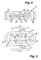
- the switching valve 6 is preferably formed as a one-piece installation unit, as well in the 3 to 5 is recognizable.
- the switching valve 6 has a rocker core 22, for example made of metal and a sheath 23 of the rocker core of soft elastic material.
- This envelope 23 forms in the region of the rocker bearing 17 a partition wall 24 between the two chambers 18,19.
- the rocker 16 and the partition wall 24 are bounded by a circumferential sealing wall 25, which also forms the outer boundary of the two chambers 18 and 19 at the same time.
- These sealing wall 25 is integrally connected in the embodiment with the partition wall 24 and the enclosure 23.
- the material for these parts is elastic, so that on the one hand the necessary seals when clamping between the connection plate 15 and the center plate 14 in the region of the sealing wall 25 and the partition 24 is given and on the other hand, but also the mobility of the rocker 16.
- Als soft elastic material for example, vulcanized elastomers or thermoplastic elastomers in question.
- the sealing wall 25 is annular and is in the functional position ( Fig.1 and 2 ) in annular grooves 26 on the one hand, the connection plate 15 and on the other hand, the center plate 14 sealingly.
- the chambers 18 and 19 are thereby limited in each case by a part of the sealing wall 25, the partition wall 24 and the middle plate 14 and the connection plate 15.
- the rocker core 22 has in the region of its rocker bearing 17, the partition wall 24 and the sealing wall 25 to the outside by cross Continuations 27 (compare Figure 3 and 5 ) which serve as external points of attack for actuating the valve rocker 16.
- an electric magnetic drive can be provided as an actuating drive for the rocker 16
- an actuating lever 28 can be seen, which is connectable to the continuations 27 and on the one hand a solenoid for adjusting the rocker engages in a switching position on the other hand acts in the opposite direction, a return spring which moves the rocker 16 in the other switching position and holds.
- the spring can be dimensioned or adjustable so that an overpressure limitation is formed.
- a manually operable, external hand lever can be provided for actuating the rocker 16.
- the continuations 27, which are guided outward on both sides of the rocker core in the area of the rocker bearing 17, can also serve for the outer mounting of the rocker 16. This storage can be done on outer housing parts.
- the rocker parts 16a, 16b have at their ends with the valve seats 29 of the closable fluid connections cooperating projections 30 as valve body, which are shaped so that in the respective inclined position of the rocker 16 is a good seal of the respective fluid connections.
- the elastic sheath 23 is designed to be somewhat larger with respect to their layer thickness and arranged the contact surface according to the tilting position of the rocker obliquely. Due to the larger layer thickness, a greater flexibility and thus a better sealing ability is given.
- the closable fluid connections 20a, 20b, 21a, 21b have the same cross sections. But there is also the possibility that the connected to the outlet valve 5 chamber 19, closable fluid connections 21a, 21b has a larger passage cross-section than that of the closable fluid ports 20a, 2Qb of the other chamber 18, which is connected to the inlet valve 4.
- the pressure forces acting on the rocker 16 cause a self-energizing closing and smaller driving forces.
- closable fluid connections 21a, 21b with the larger passage cross-section is assigned a molding 30 with a greater layer thickness than the closable fluid connections 20a, 20b of the other chamber 18, readjusting of the rocker 16 can occur in the area of the rocker support 17 when the bearing point swerves.
- the actuating forces which are applied from the outside and transmitted to the rocker 16, are composed of forces for deformation in the region of the elastic rocker bearing 17, pressure forces for closing the valve seats and forces for pressing on the valve seats with a certain deformation of the elastic Enclosure, which is required for a reliable seal.
- a pulsation damper 34 is provided, which is connected to the chamber 19, which is connected to the valve-pressure port.
- the pulsation damper 34 has a pulsation chamber with a separation membrane 35, wherein the separation membrane is supported by a volume-compressible material, for example foam.
- Both the oscillation chamber 31 and the pulsation damper 34 are integrated in the pump head 2 in the exemplary embodiment.
- the vibrating diaphragm 32 may be integrally connected to the adjacent valve plate of the intake valve 4. This also applies analogously to the separating diaphragm 35 of the pulsation damper 34, the position of the separating diaphragm and the valve plate of the outlet valve 5 being aligned relative to one another.
- an integrally continuous membrane and valve plate for the pulsation damper, the vibration chamber and the inlet and outlet valves may be provided.
Landscapes
- Engineering & Computer Science (AREA)
- General Engineering & Computer Science (AREA)
- Mechanical Engineering (AREA)
- Reciprocating Pumps (AREA)
- Details Of Reciprocating Pumps (AREA)
Claims (15)
- Pompe avec une tête de pompe, dans laquelle sont disposées une soupape d'admission et une soupape d'évacuation qui sont reliées d'un côté à une chambre de travail (7) et de l'autre côté à un raccord d'aspiration et à un raccord de refoulement, une soupape d'inversion (6) étant disposée entre les soupapes (4, 5) d'admission et d'évacuation et des raccords (10, 11) d'aspiration/refoulement de pompe, afin d'inverser le sens du débit, caractérisée en ce que la soupape d'inversion (6) est réalisée sous la forme d'une soupape à bascule avec une bascule (16) et des parties de bascule (16a, 16b) se trouvant de part et d'autre d'un palier de bascule (17), sachant que la soupape d'inversion (6) présente deux chambres (18, 19) disposées l'une à côté de l'autre et séparées l'une de l'autre, qui possèdent respectivement trois raccords fluidiques (20a, 20b, 36 ; 21a, 21b, 37), deux de ces raccords respectifs (20a, 20b ; 21a, 21b) pouvant être alternativement fermés par les parties de bascule (16a, 16b).
- Pompe selon la revendication 1, caractérisée en ce que la soupape d'inversion (6) fait partie de la tête de pompe (2), de préférence est intégrée dans celle-ci, et/ou en ce que les parties de bascule (16a, 16b) forment des corps de soupape destinés à fermer les raccords fluidiques de la soupape d'inversion (6).
- Pompe selon la revendication 1 ou 2, caractérisée en ce que, parmi les trois raccords fluidiques (20a, 20b, 36) de l'une (18) des chambres de la soupape d'inversion (6), un raccord fluidique (36) est relié au raccord d'aspiration de soupape (8) de la soupape d'admission (4) et les deux autres raccords fluidiques (20a, 20b), pouvant être alternativement fermés par la partie de bascule se trouvant dans cette chambre, sont reliés aux raccords (10, 11) d'aspiration/refoulement de pompe, en ce que, parmi les trois raccords fluidiques (21a, 21b, 37) de l'autre chambre, un raccord fluidique (37) est relié au raccord de refoulement de soupape (9) de la soupape d'évacuation (5) et les deux autres (21a, 21b) sont reliés aux raccords (10, 11) d'aspiration/refoulement de pompe, et en ce que les raccords (10, 11) d'aspiration/refoulement de pompe, en fonction de la position de la soupape d'inversion, forment alternativement un raccord de refoulement de pompe ou un raccord d'aspiration de pompe, et/ou en ce que des raccords fluidiques respectivement simultanément fermés ou simultanément ouverts (20a, 21b ; 20b, 21a) des deux chambres (18, 19) sont raccordés à des raccords différents (10,11) d'aspiration/refoulement de pompe.
- Pompe selon l'une des revendications 1 à 3, caractérisée en ce que le palier de bascule (17) est réalisé sous forme de cloison de séparation (24) entre les deux chambres (18, 19), sachant notamment que la cloison de séparation (24) et le palier de bascule (17) sont réalisés au moins sectoriellement élastiques, et sachant que la bascule (16) présente un prolongement étanché (27), dirigé vers l'extérieur, comme point d'attaque extérieur pour l'actionnement de la bascule de soupape.
- Pompe selon l'une des revendications 1 à 4, caractérisée en ce que la soupape d'inversion (6) présente une âme de bascule (22) en matériau relativement rigide, par exemple en métal, ainsi qu'un enrobage au moins sectoriel (23) de l'âme de bascule (22) en matériau souple et élastique, et/ou en ce que l'âme de bascule (22) s'étend continûment au moins jusqu'au-dessus des raccords fluidiques (20a, 20b, 21a, 21b) pouvant être alternativement fermés par les parties de bascule (16a, 16b).
- Pompe selon l'une des revendications 1 à 5, caractérisée en ce que le matériau souple et élastique, en particulier l'enrobage (23) de l'âme de bascule (22) en matériau souple et élastique, s'étend dans la région de la cloison de séparation (24) et forme celle-ci, et/ou en ce que le matériau souple et élastique, en particulier l'enrobage (23) de l'âme de bascule (22), est constitué d'un élastomère vulcanisé ou thermoplastique, et/ou en ce que les raccords fluidiques (20a, 20b, 21a, 21b) de la soupape d'inversion (6) pouvant être fermés par la bascule (16) sont munis de sièges de soupape (29).
- Pompe selon l'une des revendications 1 à 6, caractérisée en ce que les chambres de soupape (18, 19) et la cloison de séparation (24) qui se trouve entre elles sont circonscrites par une paroi d'étanchement entourante (25), sachant notamment que la paroi d'étanchement (25) est constituée d'un matériau souple et élastique et est reliée de préférence d'un seul tenant à la cloison de séparation (24) et à l'enrobage de l'âme de bascule (22).
- Pompe selon l'une des revendications 1 à 7, caractérisée en ce que l'âme de bascule (22) présente, dans la région de son palier de bascule (17), au moins un prolongement (27) traversant la cloison de séparation (24) et la paroi d'étanchement (25) vers l'extérieur comme point d'attaque extérieur pour l'actionnement de la bascule de soupape, et/ou en ce qu'un mécanisme à excentrique ou à genouillère est prévu comme mécanisme d'actionnement pour le déplacement de la bascule (16).
- Pompe selon l'une des revendications 1 à 8, caractérisée en ce qu'un entraînement électromagnétique est prévu comme entraînement pour l'actionnement de la bascule (16).
- Pompe selon l'une des revendications 1 à 9, caractérisée en ce que la bascule (16) est maintenue par force de ressort dans une position finale et peut être déplacée dans l'autre position finale par un entraînement d'actionnement, sachant notamment que le ressort pour maintenir la bascule (16) dans une position finale est dimensionné ou réglable de telle sorte qu'une limitation de surpression est formée.
- Pompe selon l'une des revendications 1 à 10, caractérisée en ce qu'un levier à main pouvant être actionné manuellement est prévu pour l'actionnement de la bascule (16), et/ou en ce que des prolongements (27) de l'âme de bascule (22), dirigés vers l'extérieur et traversant vers l'extérieur la cloison de séparation et la paroi d'étanchement, sont prévus de part et d'autre de l'âme de bascule dans la région de son palier de bascule (17), prolongements qui servent de paliers extérieurs pour la bascule (16), et/ou en ce que les raccords fluidiques (20a, 20b, 21a, 21b) pouvant être alternativement fermés par les parties de bascule (16a, 16b) présentent des sections de même taille.
- Pompe selon l'une des revendications 1 à 11, caractérisée en ce que la chambre (19) de la soupape d'inversion (6) qui est reliée à la soupape d'évacuation présente des raccords fluidiques pouvant être fermés (21a, 21b) qui possèdent une plus grande section de passage que les raccords fluidiques pouvant être fermés (20a, 20b) de l'autre chambre (18), sachant notamment qu'on associe aux raccords fluidiques pouvant être fermés (21a, 21b) de plus grande section de passage un enrobage (23) de l'âme de bascule (22) de plus grande épaisseur de couche qu'aux raccords fluidiques pouvant être fermés (20a, 20b) de l'autre chambre.
- Pompe selon l'une des revendications 1 à 12, caractérisée en ce que la chambre (18) de la soupape d'inversion (6) qui est reliée au raccord d'aspiration de soupape (8) de la pompe est reliée à une chambre d'oscillation (31), et/ou en ce que la chambre (19) de la soupape d'inversion (6) qui est reliée au raccord de refoulement de soupape (9) de la pompe est reliée à un amortisseur de pulsation (34).
- Pompe selon la revendication 13, caractérisée en ce que la chambre d'oscillation (31) et/ou l'amortisseur de pulsation (34) sont intégrés dans la tête de pompe (2), et/ou en ce que la membrane oscillante (32) et/ou la membrane séparatrice (35) sont reliées d'un seul tenant à au moins une plaque de soupape d'admission et/ou une plaque de soupape d'évacuation.
- Pompe selon l'une des revendications 1 à 14, caractérisée en ce que la tête de pompe (2) présente une plaque intermédiaire (13) avec les soupapes d'admission et d'évacuation (4, 5) ainsi qu'une plaque centrale (14) et une plaque de raccordement (15) avec la soupape d'inversion (6) entre elles, sachant notamment que la soupape d'inversion (6) avec la plaque centrale (14) et la plaque de raccordement (15) est réalisée amovible sous forme de module remplaçable, et sachant qu'au lieu de ce module remplaçable, on peut monter sur la plaque intermédiaire (13) une plaque de fermeture.
Applications Claiming Priority (2)
| Application Number | Priority Date | Filing Date | Title |
|---|---|---|---|
| DE102007023799A DE102007023799A1 (de) | 2007-05-21 | 2007-05-21 | Pumpe |
| PCT/EP2008/002183 WO2008141690A2 (fr) | 2007-05-21 | 2008-03-19 | Pompe |
Publications (2)
| Publication Number | Publication Date |
|---|---|
| EP2148986A2 EP2148986A2 (fr) | 2010-02-03 |
| EP2148986B1 true EP2148986B1 (fr) | 2011-10-26 |
Family
ID=39870426
Family Applications (1)
| Application Number | Title | Priority Date | Filing Date |
|---|---|---|---|
| EP08734663A Active EP2148986B1 (fr) | 2007-05-21 | 2008-03-19 | Pompe |
Country Status (4)
| Country | Link |
|---|---|
| EP (1) | EP2148986B1 (fr) |
| AT (1) | ATE530768T1 (fr) |
| DE (1) | DE102007023799A1 (fr) |
| WO (1) | WO2008141690A2 (fr) |
Families Citing this family (5)
| Publication number | Priority date | Publication date | Assignee | Title |
|---|---|---|---|---|
| ITBS20100166A1 (it) * | 2010-10-13 | 2012-04-14 | Camozzi S P A Societa Unipersonal E | Valvola di controllo di un fluido |
| ITBS20100165A1 (it) * | 2010-10-13 | 2012-04-14 | Camozzi S P A Societa Unipersonal E | Valvola di controllo di un fluido |
| DE202012004020U1 (de) | 2012-04-20 | 2012-05-15 | Bürkert Werke GmbH | Fluidisches Steuerelement |
| EP3705764A1 (fr) * | 2019-03-05 | 2020-09-09 | Asco Numatics GmbH | Dispositif de régulation de débit d'un fluide |
| CN113404686B (zh) * | 2021-07-30 | 2025-08-29 | 中山市伟力宝电机电器有限公司 | 一种具有水路切换结构的新型控流泵及其构成的净饮系统 |
Family Cites Families (6)
| Publication number | Priority date | Publication date | Assignee | Title |
|---|---|---|---|---|
| US2526212A (en) * | 1946-05-10 | 1950-10-17 | Separator Ab | Vacuum milking system |
| US3694112A (en) * | 1970-10-15 | 1972-09-26 | New Brunswick Scientific Co | Rotary valve pump |
| US4213298A (en) * | 1978-07-03 | 1980-07-22 | Offshore Devices, Inc. | Self-reversing hydraulic control system and self-reversing pump incorporating such system |
| US5620746A (en) * | 1995-09-22 | 1997-04-15 | Snyder, Jr.; Guy T. | Method and apparatus for reversibly pumping high viscosity fluids |
| AT407431B (de) * | 1998-02-04 | 2001-03-26 | Hygrama Ag | Wippenventil |
| DE19854620C2 (de) * | 1998-11-26 | 2001-05-17 | Festo Ag & Co | Ventileinrichtung, insbesondere Verstärker |
-
2007
- 2007-05-21 DE DE102007023799A patent/DE102007023799A1/de not_active Withdrawn
-
2008
- 2008-03-19 WO PCT/EP2008/002183 patent/WO2008141690A2/fr not_active Ceased
- 2008-03-19 EP EP08734663A patent/EP2148986B1/fr active Active
- 2008-03-19 AT AT08734663T patent/ATE530768T1/de active
Also Published As
| Publication number | Publication date |
|---|---|
| WO2008141690A3 (fr) | 2009-01-29 |
| DE102007023799A1 (de) | 2008-11-27 |
| EP2148986A2 (fr) | 2010-02-03 |
| ATE530768T1 (de) | 2011-11-15 |
| WO2008141690A2 (fr) | 2008-11-27 |
Similar Documents
| Publication | Publication Date | Title |
|---|---|---|
| EP1026407B1 (fr) | Elément de commande fluidique | |
| DE102004026567B4 (de) | Linearkompressor | |
| EP1657452B1 (fr) | Oscillateur pneumatique | |
| DE19603109C2 (de) | Kolben-Kältemittelkompressor mit verbesserter Dichtfunktion | |
| EP4328448B1 (fr) | Pompe à membrane | |
| DE69117177T2 (de) | Doppelmembranvorrichtung gegen leckage für elektrische pumpen für windschutzscheibenwaschanlagen | |
| WO1998030257A1 (fr) | Pompe pour lait maternel | |
| DE102011100218A1 (de) | Ventil | |
| EP2148986A2 (fr) | Pompe | |
| DE69902193T2 (de) | Ein Vierwege-Wählventil | |
| DE19616191A1 (de) | Steuerventil für eine Membranpumpe | |
| DE4024726A1 (de) | Membranventil | |
| DE10312355B4 (de) | Kolbenverdichter | |
| WO2005108840A1 (fr) | Soupape a clapet | |
| DE602004010443T2 (de) | Kompressor | |
| DE3152349A1 (en) | Back-flow prevention valve | |
| EP1175563A1 (fr) | Pompe a membrane comportant un orifice d'admission regle par la membrane | |
| EP1899634A1 (fr) | Dispositif a soupape | |
| EP0085298B1 (fr) | Soupape à voies multiples, en particulier pour utilisation dans des appareils de dialyse | |
| DE3855689T2 (de) | Hin- und herbewegende Schaltungsstruktur für Pumpen | |
| DE69723144T2 (de) | Doppelmembranpumpe | |
| DE102009043644B4 (de) | Mehrstufige Membran-Saugpumpe | |
| DE69401064T2 (de) | Betätigungseinrichtung eines auslassventils für einen hermetischen verdichter | |
| AT413871B (de) | Einrichtung zum regeln der fördermenge von rotationsverdichtern | |
| DE3310131C2 (fr) |
Legal Events
| Date | Code | Title | Description |
|---|---|---|---|
| PUAI | Public reference made under article 153(3) epc to a published international application that has entered the european phase |
Free format text: ORIGINAL CODE: 0009012 |
|
| 17P | Request for examination filed |
Effective date: 20091221 |
|
| AK | Designated contracting states |
Kind code of ref document: A2 Designated state(s): AT BE BG CH CY CZ DE DK EE ES FI FR GB GR HR HU IE IS IT LI LT LU LV MC MT NL NO PL PT RO SE SI SK TR |
|
| AX | Request for extension of the european patent |
Extension state: AL BA MK RS |
|
| GRAP | Despatch of communication of intention to grant a patent |
Free format text: ORIGINAL CODE: EPIDOSNIGR1 |
|
| DAX | Request for extension of the european patent (deleted) | ||
| GRAS | Grant fee paid |
Free format text: ORIGINAL CODE: EPIDOSNIGR3 |
|
| GRAA | (expected) grant |
Free format text: ORIGINAL CODE: 0009210 |
|
| AK | Designated contracting states |
Kind code of ref document: B1 Designated state(s): AT BE BG CH CY CZ DE DK EE ES FI FR GB GR HR HU IE IS IT LI LT LU LV MC MT NL NO PL PT RO SE SI SK TR |
|
| REG | Reference to a national code |
Ref country code: GB Ref legal event code: FG4D Free format text: NOT ENGLISH |
|
| REG | Reference to a national code |
Ref country code: CH Ref legal event code: EP |
|
| REG | Reference to a national code |
Ref country code: IE Ref legal event code: FG4D |
|
| REG | Reference to a national code |
Ref country code: CH Ref legal event code: NV Representative=s name: HANS RUDOLF GACHNANG PATENTANWALT |
|
| REG | Reference to a national code |
Ref country code: DE Ref legal event code: R096 Ref document number: 502008005370 Country of ref document: DE Effective date: 20120126 |
|
| REG | Reference to a national code |
Ref country code: NL Ref legal event code: VDEP Effective date: 20111026 |
|
| LTIE | Lt: invalidation of european patent or patent extension |
Effective date: 20111026 |
|
| PG25 | Lapsed in a contracting state [announced via postgrant information from national office to epo] |
Ref country code: LT Free format text: LAPSE BECAUSE OF FAILURE TO SUBMIT A TRANSLATION OF THE DESCRIPTION OR TO PAY THE FEE WITHIN THE PRESCRIBED TIME-LIMIT Effective date: 20111026 Ref country code: IS Free format text: LAPSE BECAUSE OF FAILURE TO SUBMIT A TRANSLATION OF THE DESCRIPTION OR TO PAY THE FEE WITHIN THE PRESCRIBED TIME-LIMIT Effective date: 20120226 Ref country code: NO Free format text: LAPSE BECAUSE OF FAILURE TO SUBMIT A TRANSLATION OF THE DESCRIPTION OR TO PAY THE FEE WITHIN THE PRESCRIBED TIME-LIMIT Effective date: 20120126 |
|
| PG25 | Lapsed in a contracting state [announced via postgrant information from national office to epo] |
Ref country code: PT Free format text: LAPSE BECAUSE OF FAILURE TO SUBMIT A TRANSLATION OF THE DESCRIPTION OR TO PAY THE FEE WITHIN THE PRESCRIBED TIME-LIMIT Effective date: 20120227 Ref country code: GR Free format text: LAPSE BECAUSE OF FAILURE TO SUBMIT A TRANSLATION OF THE DESCRIPTION OR TO PAY THE FEE WITHIN THE PRESCRIBED TIME-LIMIT Effective date: 20120127 Ref country code: HR Free format text: LAPSE BECAUSE OF FAILURE TO SUBMIT A TRANSLATION OF THE DESCRIPTION OR TO PAY THE FEE WITHIN THE PRESCRIBED TIME-LIMIT Effective date: 20111026 Ref country code: NL Free format text: LAPSE BECAUSE OF FAILURE TO SUBMIT A TRANSLATION OF THE DESCRIPTION OR TO PAY THE FEE WITHIN THE PRESCRIBED TIME-LIMIT Effective date: 20111026 Ref country code: PL Free format text: LAPSE BECAUSE OF FAILURE TO SUBMIT A TRANSLATION OF THE DESCRIPTION OR TO PAY THE FEE WITHIN THE PRESCRIBED TIME-LIMIT Effective date: 20111026 Ref country code: SE Free format text: LAPSE BECAUSE OF FAILURE TO SUBMIT A TRANSLATION OF THE DESCRIPTION OR TO PAY THE FEE WITHIN THE PRESCRIBED TIME-LIMIT Effective date: 20111026 Ref country code: SI Free format text: LAPSE BECAUSE OF FAILURE TO SUBMIT A TRANSLATION OF THE DESCRIPTION OR TO PAY THE FEE WITHIN THE PRESCRIBED TIME-LIMIT Effective date: 20111026 Ref country code: LV Free format text: LAPSE BECAUSE OF FAILURE TO SUBMIT A TRANSLATION OF THE DESCRIPTION OR TO PAY THE FEE WITHIN THE PRESCRIBED TIME-LIMIT Effective date: 20111026 |
|
| REG | Reference to a national code |
Ref country code: IE Ref legal event code: FD4D |
|
| PG25 | Lapsed in a contracting state [announced via postgrant information from national office to epo] |
Ref country code: CY Free format text: LAPSE BECAUSE OF FAILURE TO SUBMIT A TRANSLATION OF THE DESCRIPTION OR TO PAY THE FEE WITHIN THE PRESCRIBED TIME-LIMIT Effective date: 20111026 |
|
| PG25 | Lapsed in a contracting state [announced via postgrant information from national office to epo] |
Ref country code: CZ Free format text: LAPSE BECAUSE OF FAILURE TO SUBMIT A TRANSLATION OF THE DESCRIPTION OR TO PAY THE FEE WITHIN THE PRESCRIBED TIME-LIMIT Effective date: 20111026 Ref country code: DK Free format text: LAPSE BECAUSE OF FAILURE TO SUBMIT A TRANSLATION OF THE DESCRIPTION OR TO PAY THE FEE WITHIN THE PRESCRIBED TIME-LIMIT Effective date: 20111026 Ref country code: SK Free format text: LAPSE BECAUSE OF FAILURE TO SUBMIT A TRANSLATION OF THE DESCRIPTION OR TO PAY THE FEE WITHIN THE PRESCRIBED TIME-LIMIT Effective date: 20111026 Ref country code: EE Free format text: LAPSE BECAUSE OF FAILURE TO SUBMIT A TRANSLATION OF THE DESCRIPTION OR TO PAY THE FEE WITHIN THE PRESCRIBED TIME-LIMIT Effective date: 20111026 Ref country code: IE Free format text: LAPSE BECAUSE OF FAILURE TO SUBMIT A TRANSLATION OF THE DESCRIPTION OR TO PAY THE FEE WITHIN THE PRESCRIBED TIME-LIMIT Effective date: 20111026 Ref country code: BG Free format text: LAPSE BECAUSE OF FAILURE TO SUBMIT A TRANSLATION OF THE DESCRIPTION OR TO PAY THE FEE WITHIN THE PRESCRIBED TIME-LIMIT Effective date: 20120126 |
|
| PG25 | Lapsed in a contracting state [announced via postgrant information from national office to epo] |
Ref country code: RO Free format text: LAPSE BECAUSE OF FAILURE TO SUBMIT A TRANSLATION OF THE DESCRIPTION OR TO PAY THE FEE WITHIN THE PRESCRIBED TIME-LIMIT Effective date: 20111026 Ref country code: IT Free format text: LAPSE BECAUSE OF FAILURE TO SUBMIT A TRANSLATION OF THE DESCRIPTION OR TO PAY THE FEE WITHIN THE PRESCRIBED TIME-LIMIT Effective date: 20111026 |
|
| PLBE | No opposition filed within time limit |
Free format text: ORIGINAL CODE: 0009261 |
|
| STAA | Information on the status of an ep patent application or granted ep patent |
Free format text: STATUS: NO OPPOSITION FILED WITHIN TIME LIMIT |
|
| BERE | Be: lapsed |
Owner name: KNF FLODOS A.G. Effective date: 20120331 |
|
| 26N | No opposition filed |
Effective date: 20120727 |
|
| PG25 | Lapsed in a contracting state [announced via postgrant information from national office to epo] |
Ref country code: MC Free format text: LAPSE BECAUSE OF NON-PAYMENT OF DUE FEES Effective date: 20120331 |
|
| REG | Reference to a national code |
Ref country code: DE Ref legal event code: R097 Ref document number: 502008005370 Country of ref document: DE Effective date: 20120727 |
|
| PG25 | Lapsed in a contracting state [announced via postgrant information from national office to epo] |
Ref country code: BE Free format text: LAPSE BECAUSE OF NON-PAYMENT OF DUE FEES Effective date: 20120331 |
|
| PG25 | Lapsed in a contracting state [announced via postgrant information from national office to epo] |
Ref country code: ES Free format text: LAPSE BECAUSE OF FAILURE TO SUBMIT A TRANSLATION OF THE DESCRIPTION OR TO PAY THE FEE WITHIN THE PRESCRIBED TIME-LIMIT Effective date: 20120206 |
|
| PG25 | Lapsed in a contracting state [announced via postgrant information from national office to epo] |
Ref country code: FI Free format text: LAPSE BECAUSE OF FAILURE TO SUBMIT A TRANSLATION OF THE DESCRIPTION OR TO PAY THE FEE WITHIN THE PRESCRIBED TIME-LIMIT Effective date: 20111026 |
|
| PG25 | Lapsed in a contracting state [announced via postgrant information from national office to epo] |
Ref country code: MT Free format text: LAPSE BECAUSE OF FAILURE TO SUBMIT A TRANSLATION OF THE DESCRIPTION OR TO PAY THE FEE WITHIN THE PRESCRIBED TIME-LIMIT Effective date: 20111026 |
|
| REG | Reference to a national code |
Ref country code: CH Ref legal event code: NV Representative=s name: GACHNANG AG PATENTANWAELTE, CH |
|
| PG25 | Lapsed in a contracting state [announced via postgrant information from national office to epo] |
Ref country code: TR Free format text: LAPSE BECAUSE OF FAILURE TO SUBMIT A TRANSLATION OF THE DESCRIPTION OR TO PAY THE FEE WITHIN THE PRESCRIBED TIME-LIMIT Effective date: 20111026 |
|
| REG | Reference to a national code |
Ref country code: AT Ref legal event code: MM01 Ref document number: 530768 Country of ref document: AT Kind code of ref document: T Effective date: 20130319 |
|
| PG25 | Lapsed in a contracting state [announced via postgrant information from national office to epo] |
Ref country code: LU Free format text: LAPSE BECAUSE OF NON-PAYMENT OF DUE FEES Effective date: 20120319 |
|
| PG25 | Lapsed in a contracting state [announced via postgrant information from national office to epo] |
Ref country code: HU Free format text: LAPSE BECAUSE OF FAILURE TO SUBMIT A TRANSLATION OF THE DESCRIPTION OR TO PAY THE FEE WITHIN THE PRESCRIBED TIME-LIMIT Effective date: 20080319 |
|
| PG25 | Lapsed in a contracting state [announced via postgrant information from national office to epo] |
Ref country code: AT Free format text: LAPSE BECAUSE OF NON-PAYMENT OF DUE FEES Effective date: 20130319 |
|
| REG | Reference to a national code |
Ref country code: FR Ref legal event code: PLFP Year of fee payment: 8 |
|
| PGFP | Annual fee paid to national office [announced via postgrant information from national office to epo] |
Ref country code: CH Payment date: 20150320 Year of fee payment: 8 |
|
| PGFP | Annual fee paid to national office [announced via postgrant information from national office to epo] |
Ref country code: FR Payment date: 20150115 Year of fee payment: 8 Ref country code: GB Payment date: 20150317 Year of fee payment: 8 |
|
| REG | Reference to a national code |
Ref country code: CH Ref legal event code: PL |
|
| GBPC | Gb: european patent ceased through non-payment of renewal fee |
Effective date: 20160319 |
|
| REG | Reference to a national code |
Ref country code: FR Ref legal event code: ST Effective date: 20161130 |
|
| PG25 | Lapsed in a contracting state [announced via postgrant information from national office to epo] |
Ref country code: GB Free format text: LAPSE BECAUSE OF NON-PAYMENT OF DUE FEES Effective date: 20160319 Ref country code: FR Free format text: LAPSE BECAUSE OF NON-PAYMENT OF DUE FEES Effective date: 20160331 Ref country code: CH Free format text: LAPSE BECAUSE OF NON-PAYMENT OF DUE FEES Effective date: 20160331 Ref country code: LI Free format text: LAPSE BECAUSE OF NON-PAYMENT OF DUE FEES Effective date: 20160331 |
|
| PGFP | Annual fee paid to national office [announced via postgrant information from national office to epo] |
Ref country code: DE Payment date: 20250408 Year of fee payment: 18 |