EP4328448B1 - Pompe à membrane - Google Patents
Pompe à membrane Download PDFInfo
- Publication number
- EP4328448B1 EP4328448B1 EP23214388.3A EP23214388A EP4328448B1 EP 4328448 B1 EP4328448 B1 EP 4328448B1 EP 23214388 A EP23214388 A EP 23214388A EP 4328448 B1 EP4328448 B1 EP 4328448B1
- Authority
- EP
- European Patent Office
- Prior art keywords
- chamber
- pump
- outlet
- inlet
- valve
- Prior art date
- Legal status (The legal status is an assumption and is not a legal conclusion. Google has not performed a legal analysis and makes no representation as to the accuracy of the status listed.)
- Active
Links
Images


Classifications
-
- F—MECHANICAL ENGINEERING; LIGHTING; HEATING; WEAPONS; BLASTING
- F04—POSITIVE - DISPLACEMENT MACHINES FOR LIQUIDS; PUMPS FOR LIQUIDS OR ELASTIC FLUIDS
- F04B—POSITIVE-DISPLACEMENT MACHINES FOR LIQUIDS; PUMPS
- F04B43/00—Machines, pumps, or pumping installations having flexible working members
- F04B43/02—Machines, pumps, or pumping installations having flexible working members having plate-like flexible members, e.g. diaphragms
- F04B43/025—Machines, pumps, or pumping installations having flexible working members having plate-like flexible members, e.g. diaphragms two or more plate-like pumping members in parallel
- F04B43/026—Machines, pumps, or pumping installations having flexible working members having plate-like flexible members, e.g. diaphragms two or more plate-like pumping members in parallel each plate-like pumping flexible member working in its own pumping chamber
-
- F—MECHANICAL ENGINEERING; LIGHTING; HEATING; WEAPONS; BLASTING
- F04—POSITIVE - DISPLACEMENT MACHINES FOR LIQUIDS; PUMPS FOR LIQUIDS OR ELASTIC FLUIDS
- F04B—POSITIVE-DISPLACEMENT MACHINES FOR LIQUIDS; PUMPS
- F04B53/00—Component parts, details or accessories not provided for in, or of interest apart from, groups F04B1/00 - F04B23/00 or F04B39/00 - F04B47/00
- F04B53/10—Valves; Arrangement of valves
- F04B53/1037—Flap valves
- F04B53/1047—Flap valves the valve being formed by one or more flexible elements
-
- F—MECHANICAL ENGINEERING; LIGHTING; HEATING; WEAPONS; BLASTING
- F04—POSITIVE - DISPLACEMENT MACHINES FOR LIQUIDS; PUMPS FOR LIQUIDS OR ELASTIC FLUIDS
- F04B—POSITIVE-DISPLACEMENT MACHINES FOR LIQUIDS; PUMPS
- F04B43/00—Machines, pumps, or pumping installations having flexible working members
- F04B43/02—Machines, pumps, or pumping installations having flexible working members having plate-like flexible members, e.g. diaphragms
-
- F—MECHANICAL ENGINEERING; LIGHTING; HEATING; WEAPONS; BLASTING
- F04—POSITIVE - DISPLACEMENT MACHINES FOR LIQUIDS; PUMPS FOR LIQUIDS OR ELASTIC FLUIDS
- F04B—POSITIVE-DISPLACEMENT MACHINES FOR LIQUIDS; PUMPS
- F04B53/00—Component parts, details or accessories not provided for in, or of interest apart from, groups F04B1/00 - F04B23/00 or F04B39/00 - F04B47/00
- F04B53/10—Valves; Arrangement of valves
-
- F—MECHANICAL ENGINEERING; LIGHTING; HEATING; WEAPONS; BLASTING
- F04—POSITIVE - DISPLACEMENT MACHINES FOR LIQUIDS; PUMPS FOR LIQUIDS OR ELASTIC FLUIDS
- F04B—POSITIVE-DISPLACEMENT MACHINES FOR LIQUIDS; PUMPS
- F04B53/00—Component parts, details or accessories not provided for in, or of interest apart from, groups F04B1/00 - F04B23/00 or F04B39/00 - F04B47/00
- F04B53/10—Valves; Arrangement of valves
- F04B53/1037—Flap valves
-
- F—MECHANICAL ENGINEERING; LIGHTING; HEATING; WEAPONS; BLASTING
- F04—POSITIVE - DISPLACEMENT MACHINES FOR LIQUIDS; PUMPS FOR LIQUIDS OR ELASTIC FLUIDS
- F04B—POSITIVE-DISPLACEMENT MACHINES FOR LIQUIDS; PUMPS
- F04B53/00—Component parts, details or accessories not provided for in, or of interest apart from, groups F04B1/00 - F04B23/00 or F04B39/00 - F04B47/00
- F04B53/10—Valves; Arrangement of valves
- F04B53/1037—Flap valves
- F04B53/1047—Flap valves the valve being formed by one or more flexible elements
- F04B53/106—Flap valves the valve being formed by one or more flexible elements the valve being a membrane
-
- F—MECHANICAL ENGINEERING; LIGHTING; HEATING; WEAPONS; BLASTING
- F04—POSITIVE - DISPLACEMENT MACHINES FOR LIQUIDS; PUMPS FOR LIQUIDS OR ELASTIC FLUIDS
- F04B—POSITIVE-DISPLACEMENT MACHINES FOR LIQUIDS; PUMPS
- F04B53/00—Component parts, details or accessories not provided for in, or of interest apart from, groups F04B1/00 - F04B23/00 or F04B39/00 - F04B47/00
- F04B53/10—Valves; Arrangement of valves
- F04B53/1037—Flap valves
- F04B53/1047—Flap valves the valve being formed by one or more flexible elements
- F04B53/106—Flap valves the valve being formed by one or more flexible elements the valve being a membrane
- F04B53/1065—Flap valves the valve being formed by one or more flexible elements the valve being a membrane fixed at its centre
Definitions
- the invention relates to a diaphragm pump with a pumping chamber, wherein the pumping chamber is connected to an inlet chamber via an inlet valve and to an outlet chamber via an outlet valve.
- the invention also relates to a device for conveying fluids with a diaphragm pump.
- Diaphragm pumps which have a pump head which is essentially connected to a drive.
- the pump head has several, for example four, pump chambers, each of which is sealed from a drive chamber by means of a pump diaphragm.
- the respective pump diaphragm is connected via an associated pump element to a wobble plate arranged in the drive chamber.
- a wobble movement of the wobble plate causes the pump diaphragm to undergo a wobble, axially periodic pumping movement.
- the wobble plate is seated on a drive pin of a drive shaft connected to the drive.
- the drive pin is inclined relative to the longitudinal axis of the drive shaft and is connected to the wobble plate via a ball bearing.
- an outlet chamber is arranged centrally and an inlet chamber is arranged concentrically to the outlet chamber around the outlet chamber.
- a diaphragm pump with at least one pumping chamber is known.
- the pumping chamber is connected to an inlet chamber via an inlet valve and to an outlet chamber via an outlet valve, wherein the inlet valve has an inlet opening that can be closed by an inlet valve body, and the outlet valve has an outlet opening that can be closed by an outlet valve body.
- the outlet opening surrounds the inlet opening, or the inlet opening surrounds the outlet opening.
- WO 2013/032587 A1 describes a multi-valve compressor head having a housing defining an inlet chamber in selective communication with a cavity via a plurality of one-way inlet valves and an outlet chamber selectively communicating with the cavity via a plurality of one-way outlet valves.
- the housing also defines an inlet port for the entry of gas into the inlet chamber and an outlet port for expelling compressed gas from the outlet chamber.
- the multi-valve compressor head is in operative communication with a reciprocating diaphragm that draws gas into the inlet chamber and then into the cavity during the diaphragm's intake stroke, while expelling compressed gas from the cavity and through the outlet port during the diaphragm's exhaust stroke.
- DE 198 33 286 A1 describes a piston and cylinder air compressor having a valve plate between a top end of the cylinder and a cylinder head.
- the valve plate has a generally diametrically disposed recess receiving a suction valve reed, the valve being disposed above openings on at least one side of the recess, and the device is configured to minimize the operating clearance of the compressor.
- US 5,141,409 A describes a compression machine that can be used as a compressor, pump, or actuator.
- the machine includes a housing that houses a flexible diaphragm.
- the interior of the housing is divided into a compression chamber and a backpressure chamber by the diaphragm, which consists of a diaphragm spring or bellows.
- the diaphragm is moved back and forth to compress the fluid in the compression chamber and force it out of the compression chamber.
- the backpressure chamber is sealed with a pressurized gas.
- the pressure in the backpressure chamber opposes the pressure in the compression chamber and is maintained at about half the pressure that exists in the compression chamber during compression to suppress flexion of the diaphragm.
- Diaphragm pumps are used primarily in the chemical, pharmaceutical, and biotechnology industries, where the pumped media can be very expensive. Therefore, it is desirable that no or only a small residual volume of the pumped medium remains in the diaphragm pump after the pumping process. Furthermore, completely filling such diaphragm pumps with the fluid without air inclusions is beneficial for pumping performance.
- EP 3 327 287 A1 known diaphragm pump which has also proven itself in principle, is that the provision of an outlet opening surrounding the inlet opening or the provision of an inlet opening surrounding the outlet opening places relatively high demands on the design of the diaphragm pump, in particular on the design of individual inlet chambers which are connected to an inlet valve.
- the object of the present invention is therefore to improve the known diaphragm pumps with regard to the residual emptying and/or the venting of the pump chambers, whereby a simple structure and/or a simple design is sought.
- the invention is based on the basic idea of selecting the positioning of two outlet valves in the pumping chamber and one inlet valve in the pumping chamber more effectively in order to improve residual emptying and/or venting of the pumping chamber, but also to simplify the design.
- the invention is the first to recognize that providing two outlet valves in addition to the inlet valve can lead to a simpler design if the two outlet valves and the inlet valve are arranged in the corners of any triangle.
- a direct spatial relationship between outlet openings and inlet openings was necessary, for example by surrounding the inlet opening.
- the invention has, among other things, broken the prejudice that an offset arrangement of the outlet valves to the inlet valve does not allow for an improvement in the diaphragm pump.
- the invention is primarily based on a substantially special arrangement of an inlet valve and two outlet valves of a pumping chamber, by means of which the residual quantity of pumped medium and also the air remaining in the pumping chamber after the pumping process has ended can be reduced and even complete emptying is possible.
- One of the outlet valves can be arranged in the upper region of the pumping chamber with respect to the direction of gravitational acceleration, and the other outlet valve can be arranged in the lower region of the pumping chamber with respect to the direction of gravitational acceleration.
- the inlet valve is offset from the outlet valves of a respective pumping chamber, so that an advantageous placement of the outlet valves can be achieved.
- the inlet valve can be arranged next to or to the side of the lower of the two outlet valves.
- the diaphragm pump can empty and/or vent itself to the greatest extent possible, in particular automatically, an improved flow distribution can be made possible with a simpler design of the diaphragm pump.
- central axis or central axis of the diaphragm pump encompasses an axis that extends substantially transversely to the front plate, the valve plate, and/or the end plate (the central axis or central axis may extend substantially parallel to the normal of the front plate, the valve plate, and/or the end plate) and may be arranged substantially centrally to one of the plates.
- the central axis or central axis may extend centrally through an inlet, which is arranged centrally, in particular in a front plate.
- the term "longitudinal axis" of the pumping chamber encompasses an axis that runs, in particular, transversely to the valve plate (essentially parallel to the normal of the valve plate).
- the longitudinal axis is arranged essentially centrally to the pumping chamber, in particular essentially centrally to the pumping diaphragm.
- the longitudinal axis of the pumping chamber runs essentially parallel to the central axis of the diaphragm pump.
- the diaphragm pump has at least one pumping chamber, wherein the pumping chamber is connected to an inlet chamber via an inlet valve and to an outlet chamber via two outlet valves, wherein the outlet chamber is annular.
- the inlet valve has an inlet opening that can be closed by an inlet valve body, and each outlet valve has an outlet opening that can be closed by an outlet valve body. closable outlet opening.
- Two outlet valves are provided for the pump chamber.
- a projection of straight connecting lines, which connect adjacent outlet valves to one another, onto a projection plane transverse to the longitudinal axis of the pump chamber has no intersection points with inlet valves.
- the inlet chamber can be provided substantially centrally.
- the diaphragm pump has a pumping chamber, preferably two, and particularly preferably three, four or more pumping chambers.
- This pumping chamber or the plurality of pumping chambers can, particularly preferably, be cyclically, in particular periodically, changed in volume by an external force.
- at least one wall of the chamber volume is formed by a diaphragm, which is preferably made of one or more elastic materials, for example, plastic, rubber, elastomer, Silicone or an equivalent material, which may in particular also include one or more composite materials for increased stability and service life.
- the pump chamber can be dimensioned with regard to the maximum volume to be maintained in the pump chamber so that this maximum volume corresponds exactly to the fluid volume to be pumped within one pump stroke.
- larger pump chambers are also conceivable, which could, for example, improve the flow behavior, the efficiency of the diaphragm pump, or reduce production costs.
- a valve body within the scope of the description can in particular be formed by an elastic membrane, which generally at least partially opens the valve opening assigned to the valve body when a suitable pressure difference is applied.
- Possible materials for the valve body include, for example, metals, but in particular also plastic, rubber, elastomer, silicone or an equivalent material, which in particular can also comprise or be formed from one or more composite materials.
- a membrane is understood here in particular to be a plate which usually has elastic and/or resilient properties, whereby these elastic and/or resilient properties can also be present only in sections, for example in the edge region.
- the diaphragm can be flat in sections, but in a preferred embodiment, it is curved in the sections where it seals a pump chamber, whereby the curved section can be adapted to the stroke.
- a valve control can control the opening and closing of the valves or influence the optimization of the pumping process.
- the inlet valve and/or the outlet valve is an umbrella valve.
- An umbrella valve is understood to be a valve in which the valve body is formed by an umbrella.
- a number includes the provision of exactly the number of elements designated by the number, although further identical or similar elements are not excluded. If, for example, the description describes that a pumping chamber has two outlet valves, the pumping chamber can have exactly two, but also three, four or more Exhaust valves. The same applies to the intake valve. A pumping chamber can have exactly one intake valve, two, or even three, four, or more intake valves. It is possible for pumping chambers to have a different number of intake and/or exhaust valves.
- An inlet chamber within the scope of the description functions to hold the fluid to be pumped.
- the inlet opening can be formed directly in a wall of the inlet chamber. This enables a compact design of the diaphragm pump, particularly if, in a further preferred embodiment, the inlet opening opens directly into the pumping chamber. It is possible to provide an inlet channel between the inlet chamber and the pumping chamber, which connects the inlet chamber to the pumping chamber. This creates the possibility of designing the position of the inlet chamber within the diaphragm pump relative to the pumping chamber more freely.
- the inlet chamber is connected directly to the pumping chamber via the inlet opening without the interposition of an inlet channel, so that an additional design of an inlet channel can be omitted.
- An outlet chamber within the scope of the description serves to collect and bundle the pumped fluid, in particular for further transmission to a central outlet of the diaphragm pump, particularly in the case of multiple pump chambers and/or outlet valves.
- the outlet opening can be formed directly in a wall of the outlet chamber. This enables a compact design of the diaphragm pump, in particular if, in a further preferred embodiment, the outlet opening opens directly into the pump chamber. It is possible to provide an outlet channel between the outlet chamber and the pump chamber, which connects the outlet chamber to the pump chamber. This creates the possibility of designing the position of the outlet chamber within the diaphragm pump relative to the pump chamber more freely.
- the outlet chamber is connected directly to the pump chamber via the outlet opening without the interposition of an outlet channel, which can simplify the design of the diaphragm pump.
- an outlet valve is arranged in one edge region of the pumping chamber and an outlet valve is arranged in the opposite edge region of the pumping chamber. This allows the outlet valves to be effectively positioned to achieve improved residual fluid evacuation and venting.
- One of the edge regions can be an "upper region” of the pumping chamber, and the other of the edge regions can be a “lower region” of the pumping chamber.
- the terms “upper region” and “lower region” encompass two regions of the pumping chamber located in opposite edge regions. of the pump chamber.
- the term “upper region” functionally encompasses the placement of the outlet valve such that at least one outlet opening is provided, which is arranged as close as possible to the upper edge of the pump chamber.
- the direction “top” or “upper” refers to the direction of gravity when the diaphragm pump is installed and in the operating position.
- the direction “upper” region describes an edge region of the pump chamber that is further spaced in the direction of gravity than the "lower region”.
- the arrangement of the outlet valves in the upper or lower region encompasses positioning such that one or more outlet openings assigned to the outlet valve are arranged in the upper or lower edge region of the pump chamber.
- the inlet valve is positioned closer to the center axis of the diaphragm pump than the two outlet valves. This allows the inlet chamber to be centrally located and surrounded by the outlet chamber, which allows the outlet chamber to be positioned below the inlet chamber relative to the direction of gravity, further improving the residual emptying of the entire diaphragm pump.
- a vertical line describes a line that runs transversely to the central axis of the diaphragm pump or transversely to the longitudinal axis of the pump chamber.
- the vertical line can run parallel to the axis of gravitational acceleration, with the diaphragm pump being considered in the installed and operational state.
- the inlet valve of the pumping chamber is arranged off-center in the cross-section of the pumping chamber. This allows for an offset of the inlet valve, which can create the most free choice possible for the arrangement of the two outlet valves. Essentially, the inlet valve can be offset into a region of the pumping chamber, so that the outlet valves can be positioned more effectively and, at the same time, the connection of the pumping chamber by means of the outlet valves and the inlet valve to the inlet chamber and the outlet chamber is improved.
- off-center in the sense of the description includes a position indication that essentially corresponds to the center of the cross-section and/or the center of gravity of the cross-section, wherein a view along the longitudinal axis of the Diaphragm pump is present, insofar as it is described that the inlet valve is not located on an axis through the center of the cross section or on an axis through the center of gravity of the cross section.
- the outlet valves are arranged in a circular or circular segment shape.
- the outlet valves can be arranged essentially in a circular or circular segment shape on a valve plate, which simplifies the manufacture of the diaphragm pump.
- the outlet valves are arranged in a circular or circular segment shape around a central axis of the diaphragm pump.
- the circular or circular segment-shaped arrangement of the outlet valves can lead to a reduced design effort for an outlet chamber.
- a circular (segment-shaped) design can enable the outlet chamber to exhibit rotational invariance.
- the diaphragm pump has more than one pumping chamber, wherein the arrangement of the inlet valve and the two outlet valves of the pumping chambers essentially has rotational invariance with respect to an angle of less than 360° around the central axis of the diaphragm pump. If multiple pumping chambers are used, rotational invariance can be created, which, in addition to a simple structure or design, enables easy handling or assembly of the diaphragm pump. For example, it can be provided that a rotational invariance of 360° per number of pumping chambers can be achieved.
- an annular outlet chamber is provided.
- the outlet chamber can surround the inlet chamber, and the sealing of the outlet chamber can be limited to just one chamber, if possible.
- a common outlet chamber and a common inlet chamber can be provided, with the outlet chamber surrounding the inlet chamber and no region of the outlet chamber being arranged between two inlet chambers.
- the shape of the outlet chamber and/or inlet chamber can be simple.
- the cross-section of the pumping chamber has at least one straight section on a side wall.
- This allows an enlargement of the pumping chamber compared to a completely curved side wall.
- a completely curved side wall in the upper or lower region provides direct positioning arrangements for the outlet valves by having one inlet valve at the highest point and the other The outlet valve should be positioned at the lowest point of the pumping chamber; this is where the air is trapped or the fluid flows, but venting or residual drainage can also be achieved in straight sections.
- the offset arrangement also allows for an enlargement of the pumping chamber by providing straight sections of the side wall, particularly in the upper and/or lower areas.
- multiple pump chambers are provided, and the pump chambers are arranged in a grid of columns and rows.
- the pump chambers can also be arranged on different levels.
- the grid-like arrangement of the pump chambers essentially one above and one below the other, allows for an arrangement in which the inlet valve can be offset from a central area to effectively position the two outlet valves.
- the invention also provides a device for conveying fluids with a diaphragm pump as described in the description and/or the claims, wherein a pump head is provided with a drive chamber and a drive, and the pump chamber is sealed from the drive chamber by means of a pump diaphragm. If two or more pump chambers are provided, the pump chambers can each be sealed from the drive chamber by means of a pump diaphragm. In a preferred embodiment, the pump diaphragm can be set into a periodic axial pumping movement via an associated pump element.
- outlet opening not only describes a single opening, but is also used to represent a sum of individual openings that are delimited from one another.
- the outlet opening is segmented into several outlet opening sections that are spaced apart from one another transversely to the longitudinal axis of the pumping chamber with respect to the projection plane.
- the outlet opening sections of an outlet valve can preferably be circular or circular segment-shaped.
- the outlet opening sections belong to an outlet valve by closing the outlet opening sections with a common valve body.
- the outlet opening or the outlet opening sections can extend in one direction such that the extent of the outlet opening or the area in which the outlet opening sections of an outlet valve are located corresponds essentially to 1/5 to 1/3 of the width and/or height of the pumping chamber. This allows a high pump throughput to be achieved.
- the term "inlet opening” does not only encompass a single opening; rather, the inlet opening can be formed by inlet opening sections that are delimited from one another.
- the inlet opening is segmented into a plurality of inlet opening sections that are spaced apart from one another with respect to the projection plane transverse to the longitudinal axis of the pumping chamber.
- the inlet opening sections can preferably be arranged in a circular shape or in the shape of a circular segment in a projection plane transverse to the longitudinal axis of the pumping chamber.
- the inlet opening sections belong to an inlet valve by closing the inlet opening sections by a common valve body.
- the inlet chamber has a wall at its vertically lower end, which is configured such that the wall is substantially flush with the lower part of the inlet opening of at least one inlet valve.
- one or more lowest-lying inlet valves merge with the wall of the inlet chamber with the respective lower region of their respective inlet opening in such a way that the inlet chamber can be completely emptied via the inlet valves, and residual fluid is conveyed from the inlet chamber to the outlet chamber during the pumping process.
- the outlet chamber has a wall at its lower vertically directed region, which is configured such that the wall is substantially flush with the lower part of the outlet opening of at least one outlet valve.
- one or more lowest-lying outlet valves merge with the wall of the outlet chamber with the respective lower region of their respective outlet opening in such a way that the outlet chamber can be completely emptied via the outlet valves, and any remaining fluid is pumped from the outlet chamber out of the diaphragm pump during the pumping process.
- outlet valves of the diaphragm pump are designed similarly and particularly preferably have the same shape of the outlet opening and/or the same shape of the valve body.
- inlet valves of the diaphragm pump are designed similarly to one another and particularly preferably have the same shape of the inlet opening and/or the same shape of the valve body.
- an inlet valve plate is provided in or on which the inlet valves are arranged spatially separated.
- the diaphragm pump has four pumping chambers.
- the inlet valve plate has four spatially separated inlet valves.
- the inlet valve plate has four spatially separated inlet valves arranged in a ring.
- an outlet valve plate is provided in or on which the outlet valves are arranged spatially separated.
- the diaphragm pump has four pump chambers.
- the outlet valve plate has eight spatially separated outlet valves.
- the outlet valve plate has eight spatially separated outlet valves arranged in a ring.
- a valve plate is provided in or on which both the inlet valves and the outlet valves are arranged.
- a front plate also referred to as a pump housing, and a valve plate are provided.
- the valve plate can be arranged between the front plate on one side and a membrane support part carrying the pump membrane, for example a membrane housing cover on the other side.
- the inlet chamber or inlet chambers can be at least partially formed in the front plate.
- the inlet chamber or inlet chambers are formed by the front plate and valve plate being in contact with one another, in that recesses formed in the front plate are covered at the rear by the valve plate.
- the outlet chamber can be at least partially formed in the front plate.
- the front plate and valve plate being in contact with one another, in that recesses formed in the front plate are covered at the rear by the valve plate.
- the inlet valve or inlet valves and the outlet valves can be arranged on the valve plate.
- the pump chamber or pump chambers can be at least partially formed in the valve plate.
- the valve plate can be essentially flat. A profile on the edge, particularly for interaction with a corresponding profile on the front plate, can be provided.
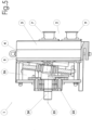
- Fig. 1 shows the pump head 2 of a diaphragm pump 1.
- the diaphragm pump 1 forms part of a device for conveying a fluid.
- the pump head 2 has a front plate 3, also referred to as a chamber housing, a valve plate 4 and an end plate 5, also referred to as a membrane carrier, with pump membranes 6, which are connected via pump elements with a Fig. 2 connected to a swashplate not shown.
- a central inlet 7 is provided in this embodiment, which opens into a central inlet chamber 8.
- an outlet 9 is provided, which is connected to an outlet chamber 10, which is annular in this embodiment and surrounds the inlet chamber 8.
- the valve plate 4 closes the inlet chamber 8 of the front plate 3 and the outlet chamber 10 of the front plate 3.
- the valve plate 4 has four inlet valves 15, which are designed as umbrella valves.
- the inlet chamber 8 is connected to the pump chamber 12 via an inlet opening 16 assigned to the inlet valve 15.
- the inlet opening 16 is segmented and has several inlet opening sections 16a.
- An inlet valve 15 is provided for each pumping chamber 12.
- Each pumping chamber 12 has two outlet valves 17.
- the two outlet valves 17 and the inlet valve 15 form a triangle in a projection onto a projection plane transverse to the longitudinal axis L of the pump chamber 12, which runs essentially parallel to a central axis M of the diaphragm pump 1, as shown in Fig. 3 is shown.
- Fig. 3 It can also be seen that adjacent outlet valves 17 on the valve plate 4 can be connected with straight connecting lines and a projection of these onto a projection plane transverse to the longitudinal axis L of the pump chamber 12 is free of intersection with the inlet valves 15.
- the two outlet valves 17 of a pumping chamber are arranged in opposite edge regions of the pumping chamber 12.
- One of the two outlet valves 17 is arranged in an upper region of the pumping chamber 12, while the other of the two outlet valves 17 is arranged in a lower region of the pumping chamber 12.
- the upper of the two outlet valves 17 allows venting of the pumping chamber 12. Residual emptying is possible using the lower of the two outlet valves 17.
- the inlet valve 15 of a pumping chamber 12 is arranged laterally offset from one of the two outlet valves 17.
- the inlet valves 15 are arranged closer to the central axis M of the diaphragm pump 1 than the outlet valves 17 of the pumping chambers 12.
- the two outlet valves 17 of a pumping chamber 12 are arranged offset from one another with respect to a vertical line running essentially along section A-A or parallel thereto.
- the inlet valve 15 is arranged off-center with respect to the cross-section of the pumping chamber 12.
- the outlet valves 17 of the diaphragm pump 1 are arranged in a circle around the central axis M of the diaphragm pump 1.
- valve plate 4 With respect to the valve plate 4, there is a rotational invariance of 90° around the central axis M of the diaphragm pump 1.
- the four pumping chambers 12 are arranged in a grid of columns and rows, with the pumping chambers 12 being arranged one above and next to each other.
- the Fig. 4 is a comparison with the Fig. 3 A differently designed cross-section of the pump chambers 12 for a further embodiment of the diaphragm pump 1 can be seen. Except for the cross-section of the pump chambers 12, the embodiments are otherwise identical and correspond to one another, so that no repetition is necessary here.
- the cross-section of the pump chamber 12 in Fig. 4 The embodiment shown has straight sections 20 on the side wall of the pumping chamber 12, which has an intersection point with the vertical and/or horizontal of a cross section of the pumping chamber 12.
- the swash plate 21 shown is connected via a ball bearing 22 to a pin 23 of a drive shaft 24.
- the pin 23 is inclined relative to the longitudinal axis 25 of the drive shaft 24 in order to generate a wobbling movement of the swash plate 21.
- the connection between the drive axis and the swash plate 21 is arranged in the region of a drive chamber 26 located upstream of the end plate 5.
- the inlet chamber 8 is sealed off from the outlet chamber 10 by a seal 27, which in the example is designed as a cord ring seal.
- the outer boundary of the outlet chamber 10 is sealed off by a seal 28, which in the example is also designed as a cord ring seal.
- the swash plate 21 By rotating the drive shaft 24 about its longitudinal axis 25, the swash plate 21 is set into a circumferential wobbling motion due to the inclination of the pin 23, without rotating with the drive shaft 24.
- the wobbling motion of the swash plate 21 sets the pump diaphragms 6 in a periodic axial pumping motion, by which negative pressure is generated in the pump chambers 12 alternately in the intake stroke by the movement towards the drive chamber 26 and positive pressure is generated in the exhaust stroke by a movement towards the front plate 3.
- the inlet valve 15 Due to the downstream arrangement of the valve shield of the inlet valve 15, the inlet valve 15 opens and the corresponding outlet valve 17 closes automatically when negative pressure prevails in the associated pump chamber 12. When excess pressure prevails in the pump chamber 12, the associated inlet valve 15 closes and the corresponding outlet valve 17 opens automatically. This pumps the pumped medium out of the pump chamber 12 through the outlet chamber 10 to the outlet 9.
Landscapes
- Engineering & Computer Science (AREA)
- Mechanical Engineering (AREA)
- General Engineering & Computer Science (AREA)
- Reciprocating Pumps (AREA)
Claims (12)
- Pompe à membrane (1) avec au moins une chambre de pompage (12), la chambre de pompage (12) étant reliée par l'intermédiaire d'une soupape d'admission (15) à une chambre d'admission (8) et par l'intermédiaire de deux soupapes de sortie (17) à une chambre de sortie (10), la soupape d'admission (15) présentant une ouverture d'admission (16) pouvant être fermée par un corps de soupape d'admission et chaque soupape de sortie (17) présentant une ouverture de sortie (18) pouvant être fermée par un corps de soupape de sortie respectif, la chambre de sortie (10) étant conçue sous forme annulaire, etles deux soupapes de sortie (17) et la soupape d'admission (15) formant un triangle dans une projection sur un plan de projection transversal à l'axe longitudinal (L) de la chambre de pompage (12), ouune projection de lignes de connexion droites reliant des soupapes de sortie voisines (17) sur le plan de projection transversal à l'axe longitudinal (L) de la chambre de pompage (12) étant sans intersection avec des soupapes d'admission (15).
- Pompe à membrane (1), selon la revendication 1, avec deux chambres de pompage (12), les chambres de pompage (12) étant reliées chacune par l'intermédiaire d'une soupape d'admission (15) à une chambre d'admission commune (8) et chacune par deux soupapes de sortie (17) à une chambre de sortie (10), la soupape d'admission (15) présentant une ouverture d'admission (16) pouvant être fermée par un corps de soupape d'admission et chaque soupape de sortie (17) présentant une ouverture de sortie (18) pouvant être fermée par un corps de soupape de sortie respectif.
- Pompe à membrane (1) selon l'une quelconque des revendications 1 ou 2, dans laquelle une soupape de sortie (17) est agencée dans une zone de bord de la chambre de pompage (12) et une soupape de sortie (17) est agencée dans la zone de bord opposée de la chambre de pompage (12).
- Pompe à membrane (1) selon l'une quelconque des revendications 1 à 3, dans laquelle la soupape d'admission (15) est agencée plus près de l'axe central (M) de la pompe à membrane (1) que les deux soupapes de sortie (17).
- Pompe à membrane (1) selon l'une quelconque des revendications 1 à 4, dans laquelle les deux soupapes de sortie (17) prévus pour la chambre de pompage (12) sont agencées en décalage l'une par rapport à l'autre par rapport à une verticale, la verticale étant transversale à l'axe central de la pompe à membrane et/ou transversale à l'axe longitudinal de la chambre de pompage.
- Pompe à membrane (1) selon l'une quelconque des revendications 1 à 5, dans laquelle la chambre d'admission (8) et la chambre de sortie (10) sont réalisées au moins partiellement dans une plaque frontale (3).
- Pompe à membrane (1) selon l'une quelconque des revendications 1 à 6, dans laquelle la chambre de pompage (12) présente une soupape d'admission (15) agencée de manière excentrée dans la section transversale de la chambre de pompage (12).
- Pompe à membrane (1) selon l'une quelconque des revendications 1 à 7, dans laquelle il est prévu plus d'une chambre de pompage (12), et dans laquelle les soupapes de sortie (17) sont agencées en forme de cercle ou de segment de cercle.
- Pompe à membrane (1) selon l'une quelconque des revendications 1 à 8, dans laquelle il est prévu plus d'une chambre de pompage (12), et l'agencement de la soupape d'admission respective (15) et des deux soupapes de sortie respectives (17) des chambres de pompage respectives (12) présente essentiellement une invariance de rotation par rapport à un angle inférieur à 360° autour de l'axe central (M).
- Pompe à membrane (1) selon l'une quelconque des revendications 1 à 9, dans laquelle la section transversale de la chambre de pompage (12) présente au moins une section essentiellement rectiligne sur une paroi latérale.
- Pompe à membrane (1) selon l'une quelconque des revendications 1 à 10, dans laquelle il est prévu plusieurs chambres de pompage (12) qui sont agencées selon une grille de colonnes et de lignes.
- Dispositif de transport de fluides avec une pompe à membrane (1) selon l'une quelconque des revendications 1 à 11, dans lequel il est prévu une tête de pompe (2) avec une chambre d'entraînement (26) et un entraînement, la chambre de pompage (12) étant rendue étanche par rapport à la chambre d'entraînement (26) au moyen d'une membrane de pompe (6).
Priority Applications (1)
| Application Number | Priority Date | Filing Date | Title |
|---|---|---|---|
| EP25184767.9A EP4644697A1 (fr) | 2018-10-11 | 2019-10-09 | Pompe à membrane |
Applications Claiming Priority (3)
| Application Number | Priority Date | Filing Date | Title |
|---|---|---|---|
| DE102018008036.7A DE102018008036A1 (de) | 2018-10-11 | 2018-10-11 | Membranpumpe |
| PCT/EP2019/077346 WO2020074576A1 (fr) | 2018-10-11 | 2019-10-09 | Pompe à membrane |
| EP19789888.5A EP3864291B1 (fr) | 2018-10-11 | 2019-10-09 | Pompe à membrane |
Related Parent Applications (1)
| Application Number | Title | Priority Date | Filing Date |
|---|---|---|---|
| EP19789888.5A Division EP3864291B1 (fr) | 2018-10-11 | 2019-10-09 | Pompe à membrane |
Related Child Applications (1)
| Application Number | Title | Priority Date | Filing Date |
|---|---|---|---|
| EP25184767.9A Division EP4644697A1 (fr) | 2018-10-11 | 2019-10-09 | Pompe à membrane |
Publications (3)
| Publication Number | Publication Date |
|---|---|
| EP4328448A2 EP4328448A2 (fr) | 2024-02-28 |
| EP4328448A3 EP4328448A3 (fr) | 2024-04-17 |
| EP4328448B1 true EP4328448B1 (fr) | 2025-06-25 |
Family
ID=68289921
Family Applications (3)
| Application Number | Title | Priority Date | Filing Date |
|---|---|---|---|
| EP25184767.9A Pending EP4644697A1 (fr) | 2018-10-11 | 2019-10-09 | Pompe à membrane |
| EP23214388.3A Active EP4328448B1 (fr) | 2018-10-11 | 2019-10-09 | Pompe à membrane |
| EP19789888.5A Active EP3864291B1 (fr) | 2018-10-11 | 2019-10-09 | Pompe à membrane |
Family Applications Before (1)
| Application Number | Title | Priority Date | Filing Date |
|---|---|---|---|
| EP25184767.9A Pending EP4644697A1 (fr) | 2018-10-11 | 2019-10-09 | Pompe à membrane |
Family Applications After (1)
| Application Number | Title | Priority Date | Filing Date |
|---|---|---|---|
| EP19789888.5A Active EP3864291B1 (fr) | 2018-10-11 | 2019-10-09 | Pompe à membrane |
Country Status (6)
| Country | Link |
|---|---|
| US (2) | US12116994B2 (fr) |
| EP (3) | EP4644697A1 (fr) |
| CN (2) | CN117869261A (fr) |
| DE (1) | DE102018008036A1 (fr) |
| ES (2) | ES2973076T3 (fr) |
| WO (1) | WO2020074576A1 (fr) |
Families Citing this family (5)
| Publication number | Priority date | Publication date | Assignee | Title |
|---|---|---|---|---|
| USD923060S1 (en) * | 2018-08-09 | 2021-06-22 | Psg Germany Gmbh | Pump |
| DE102018008037B4 (de) * | 2018-10-11 | 2020-09-10 | Psg Germany Gmbh | Spannvorrichtung für eine Vorrichtung zur Förderung von Fluid und Vorrichtung zur Förderung von Fluid |
| US11933286B1 (en) * | 2021-09-02 | 2024-03-19 | Psg Germany Gmbh | Diaphragm pumping |
| WO2025254840A1 (fr) * | 2024-06-07 | 2025-12-11 | Wanner Engineering, Inc. | Ensemble de clapets pour une pompe à membrane |
| CN119878505A (zh) * | 2025-03-31 | 2025-04-25 | 上海固思流体设备有限公司 | 一种可全排空的四柱塞隔膜泵 |
Family Cites Families (53)
| Publication number | Priority date | Publication date | Assignee | Title |
|---|---|---|---|---|
| US4158530A (en) | 1974-07-01 | 1979-06-19 | Bernstein Robert E | Pumping apparatus comprising two collapsible chambers |
| US4238992A (en) | 1978-10-30 | 1980-12-16 | Wilden Pump & Engineering Co. | Pump diaphragm |
| US4270441A (en) | 1978-10-30 | 1981-06-02 | Wilden Pump & Engineering Co. | Pump diaphragm |
| US4247264A (en) | 1979-04-13 | 1981-01-27 | Wilden Pump & Engineering Co. | Air driven diaphragm pump |
| USD275858S (en) | 1982-06-01 | 1984-10-09 | Wilden Pump & Engineering Co. | Double diaphragm pump |
| US4549467A (en) | 1983-08-03 | 1985-10-29 | Wilden Pump & Engineering Co. | Actuator valve |
| US4570833A (en) * | 1983-08-26 | 1986-02-18 | Vanderjagt John A | Pumping system |
| USD294947S (en) | 1984-08-06 | 1988-03-29 | Wilden Pump & Engineering Co. | Air driven diaphragm pump |
| USD294946S (en) | 1984-08-06 | 1988-03-29 | Wilden Pump & Engineering Co. | Air driven diaphragm pump |
| US5169296A (en) | 1989-03-10 | 1992-12-08 | Wilden James K | Air driven double diaphragm pump |
| US5007803A (en) | 1989-09-28 | 1991-04-16 | Global Pumps, Inc. | Air operated vacuum pump |
| USD331412S (en) | 1989-11-13 | 1992-12-01 | Wilden Pump & Engineering Co. | Air driven diaphragm pump |
| JPH03279684A (ja) | 1990-03-29 | 1991-12-10 | Aisin Seiki Co Ltd | 圧縮装置 |
| US5147182A (en) | 1990-10-17 | 1992-09-15 | Timmons Robert D | Integrated vacuum pressure system for a bladder pump |
| JP2514774Y2 (ja) | 1992-09-18 | 1996-10-23 | 日東工器株式会社 | 往復動ポンプ |
| US5378122A (en) | 1993-02-16 | 1995-01-03 | Wilden Pump & Engineering Co. | Air driven diaphragm pump |
| USD382277S (en) | 1996-02-12 | 1997-08-12 | Graco Inc. | Double diaphragm pump |
| US5743170A (en) | 1996-03-27 | 1998-04-28 | Wilden Pump & Engineering Co. | Diaphragm mechanism for an air driven diaphragm pump |
| US5927954A (en) | 1996-05-17 | 1999-07-27 | Wilden Pump & Engineering Co. | Amplified pressure air driven diaphragm pump and pressure relief value therefor |
| US5687633A (en) | 1996-07-09 | 1997-11-18 | Westinghouse Air Brake Company | Insert type member for use in a flexible type pump diaphragm |
| US5634391A (en) | 1996-07-09 | 1997-06-03 | Westinghouse Air Brake Co. | Inert plastic coated flexible type diaphragm for application in a sanitary type pump |
| GB9715741D0 (en) * | 1997-07-26 | 1997-10-01 | Knorr Bremse Systeme | Improvements to gas compressors |
| DE19736703C2 (de) | 1997-08-20 | 1999-07-29 | Mannesmann Ag | Vorrichtung zur Ansteuerung eines Quetschventils |
| US5957670A (en) | 1997-08-26 | 1999-09-28 | Wilden Pump & Engineering Co. | Air driven diaphragm pump |
| US6102363A (en) | 1998-04-20 | 2000-08-15 | Wilden Pump & Engineering Co. | Actuator for reciprocating air driven devices |
| US6257845B1 (en) | 1998-07-14 | 2001-07-10 | Wilden Pump & Engineering Co. | Air driven pumps and components therefor |
| US6152705A (en) | 1998-07-15 | 2000-11-28 | Wilden Pump & Engineering Co. | Air drive pumps and components therefor |
| US6230609B1 (en) | 1999-06-03 | 2001-05-15 | Norton Performance Plastics Corporation | Fluoropolymer diaphragm with integral attachment device |
| USD448778S1 (en) | 1999-10-08 | 2001-10-02 | Smc Kabushiki Kaisha | Diaphragm pump |
| US6343539B1 (en) | 1999-11-10 | 2002-02-05 | Benjamin R. Du | Multiple layer pump diaphragm |
| DE10117531A1 (de) | 2001-04-07 | 2002-10-17 | Quattroflow Fluid Systems Gmbh | Membranpumpe |
| USD498766S1 (en) | 2003-08-07 | 2004-11-23 | Smc Corporation | Diaphragm pump |
| USD499116S1 (en) | 2003-08-07 | 2004-11-30 | Smc Corporation | Diaphragm pump |
| US7063516B2 (en) | 2004-05-04 | 2006-06-20 | Wilden Pump And Engineering Llc | One-way valve |
| US7125229B2 (en) | 2004-05-10 | 2006-10-24 | Wilden Pump And Engineering Llc | Reciprocating air distribution system |
| USD512441S1 (en) | 2004-07-26 | 2005-12-06 | Smc Corporation | Process pump |
| US7517199B2 (en) | 2004-11-17 | 2009-04-14 | Proportion Air Incorporated | Control system for an air operated diaphragm pump |
| DE102005006522B3 (de) | 2005-02-11 | 2006-08-03 | J. Wagner Ag | Vorrichtung zum Fördern von Beschichtungspulver und Verfahren zum Fördern von Pulver mit der Fördervorrichtung |
| JP4668027B2 (ja) | 2005-10-17 | 2011-04-13 | シーケーディ株式会社 | 薬液供給システム |
| US7399168B1 (en) | 2005-12-19 | 2008-07-15 | Wilden Pump And Engineering Llc | Air driven diaphragm pump |
| DE102006048454B3 (de) | 2006-10-11 | 2007-11-15 | Manfred Butsch | Vorrichtung zur Ansteuerung eines Quetschventils |
| DE202006020237U1 (de) | 2006-10-25 | 2008-02-21 | Quattroflow Fluid Systems Gmbh & Co. Kg | Membranpumpe |
| DE102007005313A1 (de) | 2007-02-02 | 2008-08-07 | Itw Gema Ag | Beschichtungspulver-Fördervorrichtung |
| US8282368B2 (en) * | 2007-08-22 | 2012-10-09 | Ford Global Technologies, Llc | Check valve |
| US8157549B2 (en) * | 2008-02-26 | 2012-04-17 | Microjet Technology Co., Ltd. | Multi-channel fluid conveying apparatus |
| DE102008035592B4 (de) * | 2008-07-31 | 2014-10-30 | Almatec Maschinenbau Gmbh | Membranpumpe |
| DE102008037672B4 (de) | 2008-08-14 | 2016-01-14 | Danfoss A/S | Kolbenverdichter, insbesondere Kältemittelverdichter |
| WO2012088312A2 (fr) | 2010-12-21 | 2012-06-28 | Sta-Rite Industries, Llc | Système de moteur et de pompe à diaphragme et procédé |
| US20130055887A1 (en) | 2011-09-02 | 2013-03-07 | Allied Healthcare Products Inc. | Multiple valve head compressor apparatus |
| USD707259S1 (en) | 2013-03-18 | 2014-06-17 | Timmer-Pneumatik Gmbh | Double membrane pump |
| US10082138B2 (en) * | 2014-08-25 | 2018-09-25 | Flowserve Management Company | Valve and valve seat for a diaphragm pump |
| DE102015205651A1 (de) * | 2015-03-27 | 2016-09-29 | Gardner Denver Thomas Gmbh | Hubverdrängerpumpe und dafür einsetzbares Überdruck-Ventil mit einer elastischen Ventilmembran |
| EP3327287B1 (fr) * | 2016-11-23 | 2024-05-15 | PSG Germany GmbH | Pompe à membrane |
-
2018
- 2018-10-11 DE DE102018008036.7A patent/DE102018008036A1/de active Pending
-
2019
- 2019-10-09 EP EP25184767.9A patent/EP4644697A1/fr active Pending
- 2019-10-09 ES ES19789888T patent/ES2973076T3/es active Active
- 2019-10-09 CN CN202311695858.XA patent/CN117869261A/zh active Pending
- 2019-10-09 ES ES23214388T patent/ES3046816T3/es active Active
- 2019-10-09 EP EP23214388.3A patent/EP4328448B1/fr active Active
- 2019-10-09 CN CN201980066588.1A patent/CN113195895B/zh active Active
- 2019-10-09 WO PCT/EP2019/077346 patent/WO2020074576A1/fr not_active Ceased
- 2019-10-09 EP EP19789888.5A patent/EP3864291B1/fr active Active
- 2019-10-09 US US17/281,964 patent/US12116994B2/en active Active
-
2024
- 2024-09-12 US US18/883,351 patent/US20250003404A1/en active Pending
Also Published As
| Publication number | Publication date |
|---|---|
| EP4328448A2 (fr) | 2024-02-28 |
| EP3864291A1 (fr) | 2021-08-18 |
| WO2020074576A1 (fr) | 2020-04-16 |
| EP3864291B1 (fr) | 2023-12-06 |
| CN117869261A (zh) | 2024-04-12 |
| DE102018008036A1 (de) | 2020-04-16 |
| CN113195895A (zh) | 2021-07-30 |
| US12116994B2 (en) | 2024-10-15 |
| US20210355934A1 (en) | 2021-11-18 |
| ES2973076T3 (es) | 2024-06-18 |
| ES3046816T3 (en) | 2025-12-02 |
| US20250003404A1 (en) | 2025-01-02 |
| EP4328448A3 (fr) | 2024-04-17 |
| EP4644697A1 (fr) | 2025-11-05 |
| EP3864291C0 (fr) | 2023-12-06 |
| CN113195895B (zh) | 2023-12-29 |
Similar Documents
| Publication | Publication Date | Title |
|---|---|---|
| EP4328448B1 (fr) | Pompe à membrane | |
| EP3327287B1 (fr) | Pompe à membrane | |
| DE4007932C2 (fr) | ||
| EP2761180B1 (fr) | Pompe volumétrique | |
| EP0604740B1 (fr) | Pompe à membrane | |
| DE102008035592B4 (de) | Membranpumpe | |
| EP0733802B1 (fr) | Pompe à membrane façonnée | |
| DE3718967C2 (de) | Pumpe | |
| DE102007039964B4 (de) | Hochdruck-Doppelmembranpumpe und Membranelement für eine solche Pumpe | |
| DE2502566B2 (de) | Membranpumpe | |
| DE3708327A1 (de) | Einrichtung zum foerdern von fluessigkeit auf zwei ueber spritzduesen zu netzende, mit abstand voneinander angeordnete scheibenbereiche eines kraftfahrzeugs | |
| DE2333380A1 (de) | Hydrostatische pumpen/motoreinheit | |
| DE3042328A1 (de) | Kolbenpumpe | |
| DE10312899A1 (de) | Membranpumpe | |
| EP2057376B1 (fr) | Pompe à membrane comprenant deux corps de membrane et deux boîtiers de pompe séparés | |
| EP2148986B1 (fr) | Pompe | |
| DE69723144T2 (de) | Doppelmembranpumpe | |
| EP2079932A1 (fr) | Pompe à vide avec une soupape de sortie | |
| EP1702162A1 (fr) | Compresseur a piston pour comprimer des substances gazeuses dans au moins deux chambres de travail | |
| DE10210295A1 (de) | Struktur zur Entfernung von Fremdstoffen in einem Fluidkreislauf und ein damit ausgestatteter Kompressor | |
| DE4034267C2 (de) | Radialkolbenpumpe | |
| DE102015105304A1 (de) | Membranpumpe | |
| EP0929743B1 (fr) | Pompe a piston radial | |
| DE102017117983A1 (de) | Pumpen-Einheit, damit ausgestattete Lagervorrichtung sowie Verfahren zum Betreiben der Lagervorrichtung | |
| EP0263199B2 (fr) | Compresseur à membrane |
Legal Events
| Date | Code | Title | Description |
|---|---|---|---|
| PUAI | Public reference made under article 153(3) epc to a published international application that has entered the european phase |
Free format text: ORIGINAL CODE: 0009012 |
|
| STAA | Information on the status of an ep patent application or granted ep patent |
Free format text: STATUS: REQUEST FOR EXAMINATION WAS MADE |
|
| 17P | Request for examination filed |
Effective date: 20231205 |
|
| AC | Divisional application: reference to earlier application |
Ref document number: 3864291 Country of ref document: EP Kind code of ref document: P |
|
| AK | Designated contracting states |
Kind code of ref document: A2 Designated state(s): AL AT BE BG CH CY CZ DE DK EE ES FI FR GB GR HR HU IE IS IT LI LT LU LV MC MK MT NL NO PL PT RO RS SE SI SK SM TR |
|
| REG | Reference to a national code |
Ref country code: DE Free format text: PREVIOUS MAIN CLASS: F04B0053100000 Ref country code: DE Ref legal event code: R079 Ref document number: 502019013529 Country of ref document: DE Free format text: PREVIOUS MAIN CLASS: F04B0053100000 Ipc: F04B0043020000 |
|
| PUAL | Search report despatched |
Free format text: ORIGINAL CODE: 0009013 |
|
| AK | Designated contracting states |
Kind code of ref document: A3 Designated state(s): AL AT BE BG CH CY CZ DE DK EE ES FI FR GB GR HR HU IE IS IT LI LT LU LV MC MK MT NL NO PL PT RO RS SE SI SK SM TR |
|
| RIC1 | Information provided on ipc code assigned before grant |
Ipc: F04B 53/10 20060101ALI20240314BHEP Ipc: F04B 43/02 20060101AFI20240314BHEP |
|
| REG | Reference to a national code |
Ref country code: HK Ref legal event code: DE Ref document number: 40108455 Country of ref document: HK |
|
| GRAP | Despatch of communication of intention to grant a patent |
Free format text: ORIGINAL CODE: EPIDOSNIGR1 |
|
| STAA | Information on the status of an ep patent application or granted ep patent |
Free format text: STATUS: GRANT OF PATENT IS INTENDED |
|
| INTG | Intention to grant announced |
Effective date: 20250121 |
|
| GRAS | Grant fee paid |
Free format text: ORIGINAL CODE: EPIDOSNIGR3 |
|
| GRAA | (expected) grant |
Free format text: ORIGINAL CODE: 0009210 |
|
| STAA | Information on the status of an ep patent application or granted ep patent |
Free format text: STATUS: THE PATENT HAS BEEN GRANTED |
|
| AC | Divisional application: reference to earlier application |
Ref document number: 3864291 Country of ref document: EP Kind code of ref document: P |
|
| AK | Designated contracting states |
Kind code of ref document: B1 Designated state(s): AL AT BE BG CH CY CZ DE DK EE ES FI FR GB GR HR HU IE IS IT LI LT LU LV MC MK MT NL NO PL PT RO RS SE SI SK SM TR |
|
| REG | Reference to a national code |
Ref country code: GB Ref legal event code: FG4D Free format text: NOT ENGLISH |
|
| REG | Reference to a national code |
Ref country code: CH Ref legal event code: EP |
|
| REG | Reference to a national code |
Ref country code: CH Ref legal event code: EP |
|
| REG | Reference to a national code |
Ref country code: IE Ref legal event code: FG4D Free format text: LANGUAGE OF EP DOCUMENT: GERMAN |
|
| REG | Reference to a national code |
Ref country code: DE Ref legal event code: R096 Ref document number: 502019013529 Country of ref document: DE |
|
| P01 | Opt-out of the competence of the unified patent court (upc) registered |
Free format text: CASE NUMBER: APP_32253/2025 Effective date: 20250701 |
|
| PG25 | Lapsed in a contracting state [announced via postgrant information from national office to epo] |
Ref country code: FI Free format text: LAPSE BECAUSE OF FAILURE TO SUBMIT A TRANSLATION OF THE DESCRIPTION OR TO PAY THE FEE WITHIN THE PRESCRIBED TIME-LIMIT Effective date: 20250625 |
|
| REG | Reference to a national code |
Ref country code: LT Ref legal event code: MG9D |
|
| PG25 | Lapsed in a contracting state [announced via postgrant information from national office to epo] |
Ref country code: NO Free format text: LAPSE BECAUSE OF FAILURE TO SUBMIT A TRANSLATION OF THE DESCRIPTION OR TO PAY THE FEE WITHIN THE PRESCRIBED TIME-LIMIT Effective date: 20250925 Ref country code: GR Free format text: LAPSE BECAUSE OF FAILURE TO SUBMIT A TRANSLATION OF THE DESCRIPTION OR TO PAY THE FEE WITHIN THE PRESCRIBED TIME-LIMIT Effective date: 20250926 |
|
| PG25 | Lapsed in a contracting state [announced via postgrant information from national office to epo] |
Ref country code: BG Free format text: LAPSE BECAUSE OF FAILURE TO SUBMIT A TRANSLATION OF THE DESCRIPTION OR TO PAY THE FEE WITHIN THE PRESCRIBED TIME-LIMIT Effective date: 20250625 |
|
| PG25 | Lapsed in a contracting state [announced via postgrant information from national office to epo] |
Ref country code: HR Free format text: LAPSE BECAUSE OF FAILURE TO SUBMIT A TRANSLATION OF THE DESCRIPTION OR TO PAY THE FEE WITHIN THE PRESCRIBED TIME-LIMIT Effective date: 20250625 |
|
| PG25 | Lapsed in a contracting state [announced via postgrant information from national office to epo] |
Ref country code: RS Free format text: LAPSE BECAUSE OF FAILURE TO SUBMIT A TRANSLATION OF THE DESCRIPTION OR TO PAY THE FEE WITHIN THE PRESCRIBED TIME-LIMIT Effective date: 20250925 |
|
| PG25 | Lapsed in a contracting state [announced via postgrant information from national office to epo] |
Ref country code: LV Free format text: LAPSE BECAUSE OF FAILURE TO SUBMIT A TRANSLATION OF THE DESCRIPTION OR TO PAY THE FEE WITHIN THE PRESCRIBED TIME-LIMIT Effective date: 20250625 |
|
| REG | Reference to a national code |
Ref country code: NL Ref legal event code: MP Effective date: 20250625 |
|
| REG | Reference to a national code |
Ref country code: CH Ref legal event code: U11 Free format text: ST27 STATUS EVENT CODE: U-0-0-U10-U11 (AS PROVIDED BY THE NATIONAL OFFICE) Effective date: 20251101 |
|
| PG25 | Lapsed in a contracting state [announced via postgrant information from national office to epo] |
Ref country code: NL Free format text: LAPSE BECAUSE OF FAILURE TO SUBMIT A TRANSLATION OF THE DESCRIPTION OR TO PAY THE FEE WITHIN THE PRESCRIBED TIME-LIMIT Effective date: 20250625 |
|
| REG | Reference to a national code |
Ref country code: ES Ref legal event code: FG2A Ref document number: 3046816 Country of ref document: ES Kind code of ref document: T3 Effective date: 20251202 |
|
| PG25 | Lapsed in a contracting state [announced via postgrant information from national office to epo] |
Ref country code: PT Free format text: LAPSE BECAUSE OF FAILURE TO SUBMIT A TRANSLATION OF THE DESCRIPTION OR TO PAY THE FEE WITHIN THE PRESCRIBED TIME-LIMIT Effective date: 20251027 |
|
| PG25 | Lapsed in a contracting state [announced via postgrant information from national office to epo] |
Ref country code: IS Free format text: LAPSE BECAUSE OF FAILURE TO SUBMIT A TRANSLATION OF THE DESCRIPTION OR TO PAY THE FEE WITHIN THE PRESCRIBED TIME-LIMIT Effective date: 20251025 |
|
| PGFP | Annual fee paid to national office [announced via postgrant information from national office to epo] |
Ref country code: DE Payment date: 20251027 Year of fee payment: 7 |
|
| PGFP | Annual fee paid to national office [announced via postgrant information from national office to epo] |
Ref country code: GB Payment date: 20251024 Year of fee payment: 7 |
|
| PG25 | Lapsed in a contracting state [announced via postgrant information from national office to epo] |
Ref country code: SM Free format text: LAPSE BECAUSE OF FAILURE TO SUBMIT A TRANSLATION OF THE DESCRIPTION OR TO PAY THE FEE WITHIN THE PRESCRIBED TIME-LIMIT Effective date: 20250625 |
|
| PGFP | Annual fee paid to national office [announced via postgrant information from national office to epo] |
Ref country code: FR Payment date: 20251028 Year of fee payment: 7 |
|
| PGFP | Annual fee paid to national office [announced via postgrant information from national office to epo] |
Ref country code: CH Payment date: 20251101 Year of fee payment: 7 |
|
| PGFP | Annual fee paid to national office [announced via postgrant information from national office to epo] |
Ref country code: IE Payment date: 20251022 Year of fee payment: 7 Ref country code: CZ Payment date: 20250930 Year of fee payment: 7 |
|
| PG25 | Lapsed in a contracting state [announced via postgrant information from national office to epo] |
Ref country code: PL Free format text: LAPSE BECAUSE OF FAILURE TO SUBMIT A TRANSLATION OF THE DESCRIPTION OR TO PAY THE FEE WITHIN THE PRESCRIBED TIME-LIMIT Effective date: 20250625 |
|
| PG25 | Lapsed in a contracting state [announced via postgrant information from national office to epo] |
Ref country code: EE Free format text: LAPSE BECAUSE OF FAILURE TO SUBMIT A TRANSLATION OF THE DESCRIPTION OR TO PAY THE FEE WITHIN THE PRESCRIBED TIME-LIMIT Effective date: 20250625 |
|
| PG25 | Lapsed in a contracting state [announced via postgrant information from national office to epo] |
Ref country code: SK Free format text: LAPSE BECAUSE OF FAILURE TO SUBMIT A TRANSLATION OF THE DESCRIPTION OR TO PAY THE FEE WITHIN THE PRESCRIBED TIME-LIMIT Effective date: 20250625 |
|
| PGFP | Annual fee paid to national office [announced via postgrant information from national office to epo] |
Ref country code: ES Payment date: 20251104 Year of fee payment: 7 |
|
| PG25 | Lapsed in a contracting state [announced via postgrant information from national office to epo] |
Ref country code: RO Free format text: LAPSE BECAUSE OF FAILURE TO SUBMIT A TRANSLATION OF THE DESCRIPTION OR TO PAY THE FEE WITHIN THE PRESCRIBED TIME-LIMIT Effective date: 20250625 |
|
| PG25 | Lapsed in a contracting state [announced via postgrant information from national office to epo] |
Ref country code: DK Free format text: LAPSE BECAUSE OF FAILURE TO SUBMIT A TRANSLATION OF THE DESCRIPTION OR TO PAY THE FEE WITHIN THE PRESCRIBED TIME-LIMIT Effective date: 20250625 |
|
| PG25 | Lapsed in a contracting state [announced via postgrant information from national office to epo] |
Ref country code: IT Free format text: LAPSE BECAUSE OF FAILURE TO SUBMIT A TRANSLATION OF THE DESCRIPTION OR TO PAY THE FEE WITHIN THE PRESCRIBED TIME-LIMIT Effective date: 20250625 |
|
| PLBE | No opposition filed within time limit |
Free format text: ORIGINAL CODE: 0009261 |
|
| STAA | Information on the status of an ep patent application or granted ep patent |
Free format text: STATUS: NO OPPOSITION FILED WITHIN TIME LIMIT |