EP2149021B1 - Aufbewahrungsgehäuse, verfahren und vorrichtung zur herstellung von kohlenmonoxid und/oder wasserstoff durch kryogene trennung, einschliesslich solch eines gehäuses - Google Patents
Aufbewahrungsgehäuse, verfahren und vorrichtung zur herstellung von kohlenmonoxid und/oder wasserstoff durch kryogene trennung, einschliesslich solch eines gehäuses Download PDFInfo
- Publication number
- EP2149021B1 EP2149021B1 EP08805790.6A EP08805790A EP2149021B1 EP 2149021 B1 EP2149021 B1 EP 2149021B1 EP 08805790 A EP08805790 A EP 08805790A EP 2149021 B1 EP2149021 B1 EP 2149021B1
- Authority
- EP
- European Patent Office
- Prior art keywords
- liquid
- column
- carbon monoxide
- enclosure
- discharging
- Prior art date
- Legal status (The legal status is an assumption and is not a legal conclusion. Google has not performed a legal analysis and makes no representation as to the accuracy of the status listed.)
- Active
Links
Images



Classifications
-
- F—MECHANICAL ENGINEERING; LIGHTING; HEATING; WEAPONS; BLASTING
- F25—REFRIGERATION OR COOLING; COMBINED HEATING AND REFRIGERATION SYSTEMS; HEAT PUMP SYSTEMS; MANUFACTURE OR STORAGE OF ICE; LIQUEFACTION SOLIDIFICATION OF GASES
- F25J—LIQUEFACTION, SOLIDIFICATION OR SEPARATION OF GASES OR GASEOUS OR LIQUEFIED GASEOUS MIXTURES BY PRESSURE AND COLD TREATMENT OR BY BRINGING THEM INTO THE SUPERCRITICAL STATE
- F25J3/00—Processes or apparatus for separating the constituents of gaseous or liquefied gaseous mixtures involving the use of liquefaction or solidification
- F25J3/02—Processes or apparatus for separating the constituents of gaseous or liquefied gaseous mixtures involving the use of liquefaction or solidification by rectification, i.e. by continuous interchange of heat and material between a vapour stream and a liquid stream
- F25J3/0204—Processes or apparatus for separating the constituents of gaseous or liquefied gaseous mixtures involving the use of liquefaction or solidification by rectification, i.e. by continuous interchange of heat and material between a vapour stream and a liquid stream characterised by the feed stream
- F25J3/0223—H2/CO mixtures, i.e. synthesis gas; Water gas or shifted synthesis gas
-
- F—MECHANICAL ENGINEERING; LIGHTING; HEATING; WEAPONS; BLASTING
- F25—REFRIGERATION OR COOLING; COMBINED HEATING AND REFRIGERATION SYSTEMS; HEAT PUMP SYSTEMS; MANUFACTURE OR STORAGE OF ICE; LIQUEFACTION SOLIDIFICATION OF GASES
- F25J—LIQUEFACTION, SOLIDIFICATION OR SEPARATION OF GASES OR GASEOUS OR LIQUEFIED GASEOUS MIXTURES BY PRESSURE AND COLD TREATMENT OR BY BRINGING THEM INTO THE SUPERCRITICAL STATE
- F25J3/00—Processes or apparatus for separating the constituents of gaseous or liquefied gaseous mixtures involving the use of liquefaction or solidification
- F25J3/02—Processes or apparatus for separating the constituents of gaseous or liquefied gaseous mixtures involving the use of liquefaction or solidification by rectification, i.e. by continuous interchange of heat and material between a vapour stream and a liquid stream
- F25J3/0228—Processes or apparatus for separating the constituents of gaseous or liquefied gaseous mixtures involving the use of liquefaction or solidification by rectification, i.e. by continuous interchange of heat and material between a vapour stream and a liquid stream characterised by the separated product stream
- F25J3/0252—Processes or apparatus for separating the constituents of gaseous or liquefied gaseous mixtures involving the use of liquefaction or solidification by rectification, i.e. by continuous interchange of heat and material between a vapour stream and a liquid stream characterised by the separated product stream separation of hydrogen
-
- F—MECHANICAL ENGINEERING; LIGHTING; HEATING; WEAPONS; BLASTING
- F25—REFRIGERATION OR COOLING; COMBINED HEATING AND REFRIGERATION SYSTEMS; HEAT PUMP SYSTEMS; MANUFACTURE OR STORAGE OF ICE; LIQUEFACTION SOLIDIFICATION OF GASES
- F25J—LIQUEFACTION, SOLIDIFICATION OR SEPARATION OF GASES OR GASEOUS OR LIQUEFIED GASEOUS MIXTURES BY PRESSURE AND COLD TREATMENT OR BY BRINGING THEM INTO THE SUPERCRITICAL STATE
- F25J3/00—Processes or apparatus for separating the constituents of gaseous or liquefied gaseous mixtures involving the use of liquefaction or solidification
- F25J3/02—Processes or apparatus for separating the constituents of gaseous or liquefied gaseous mixtures involving the use of liquefaction or solidification by rectification, i.e. by continuous interchange of heat and material between a vapour stream and a liquid stream
- F25J3/0228—Processes or apparatus for separating the constituents of gaseous or liquefied gaseous mixtures involving the use of liquefaction or solidification by rectification, i.e. by continuous interchange of heat and material between a vapour stream and a liquid stream characterised by the separated product stream
- F25J3/0257—Processes or apparatus for separating the constituents of gaseous or liquefied gaseous mixtures involving the use of liquefaction or solidification by rectification, i.e. by continuous interchange of heat and material between a vapour stream and a liquid stream characterised by the separated product stream separation of nitrogen
-
- F—MECHANICAL ENGINEERING; LIGHTING; HEATING; WEAPONS; BLASTING
- F25—REFRIGERATION OR COOLING; COMBINED HEATING AND REFRIGERATION SYSTEMS; HEAT PUMP SYSTEMS; MANUFACTURE OR STORAGE OF ICE; LIQUEFACTION SOLIDIFICATION OF GASES
- F25J—LIQUEFACTION, SOLIDIFICATION OR SEPARATION OF GASES OR GASEOUS OR LIQUEFIED GASEOUS MIXTURES BY PRESSURE AND COLD TREATMENT OR BY BRINGING THEM INTO THE SUPERCRITICAL STATE
- F25J3/00—Processes or apparatus for separating the constituents of gaseous or liquefied gaseous mixtures involving the use of liquefaction or solidification
- F25J3/02—Processes or apparatus for separating the constituents of gaseous or liquefied gaseous mixtures involving the use of liquefaction or solidification by rectification, i.e. by continuous interchange of heat and material between a vapour stream and a liquid stream
- F25J3/0228—Processes or apparatus for separating the constituents of gaseous or liquefied gaseous mixtures involving the use of liquefaction or solidification by rectification, i.e. by continuous interchange of heat and material between a vapour stream and a liquid stream characterised by the separated product stream
- F25J3/0261—Processes or apparatus for separating the constituents of gaseous or liquefied gaseous mixtures involving the use of liquefaction or solidification by rectification, i.e. by continuous interchange of heat and material between a vapour stream and a liquid stream characterised by the separated product stream separation of carbon monoxide
-
- F—MECHANICAL ENGINEERING; LIGHTING; HEATING; WEAPONS; BLASTING
- F25—REFRIGERATION OR COOLING; COMBINED HEATING AND REFRIGERATION SYSTEMS; HEAT PUMP SYSTEMS; MANUFACTURE OR STORAGE OF ICE; LIQUEFACTION SOLIDIFICATION OF GASES
- F25J—LIQUEFACTION, SOLIDIFICATION OR SEPARATION OF GASES OR GASEOUS OR LIQUEFIED GASEOUS MIXTURES BY PRESSURE AND COLD TREATMENT OR BY BRINGING THEM INTO THE SUPERCRITICAL STATE
- F25J5/00—Arrangements of cold exchangers or cold accumulators in separation or liquefaction plants
- F25J5/002—Arrangements of cold exchangers or cold accumulators in separation or liquefaction plants for continuously recuperating cold, i.e. in a so-called recuperative heat exchanger
- F25J5/005—Arrangements of cold exchangers or cold accumulators in separation or liquefaction plants for continuously recuperating cold, i.e. in a so-called recuperative heat exchanger in a reboiler-condenser, e.g. within a column
-
- F—MECHANICAL ENGINEERING; LIGHTING; HEATING; WEAPONS; BLASTING
- F25—REFRIGERATION OR COOLING; COMBINED HEATING AND REFRIGERATION SYSTEMS; HEAT PUMP SYSTEMS; MANUFACTURE OR STORAGE OF ICE; LIQUEFACTION SOLIDIFICATION OF GASES
- F25J—LIQUEFACTION, SOLIDIFICATION OR SEPARATION OF GASES OR GASEOUS OR LIQUEFIED GASEOUS MIXTURES BY PRESSURE AND COLD TREATMENT OR BY BRINGING THEM INTO THE SUPERCRITICAL STATE
- F25J2200/00—Processes or apparatus using separation by rectification
- F25J2200/40—Features relating to the provision of boil-up in the bottom of a column
-
- F—MECHANICAL ENGINEERING; LIGHTING; HEATING; WEAPONS; BLASTING
- F25—REFRIGERATION OR COOLING; COMBINED HEATING AND REFRIGERATION SYSTEMS; HEAT PUMP SYSTEMS; MANUFACTURE OR STORAGE OF ICE; LIQUEFACTION SOLIDIFICATION OF GASES
- F25J—LIQUEFACTION, SOLIDIFICATION OR SEPARATION OF GASES OR GASEOUS OR LIQUEFIED GASEOUS MIXTURES BY PRESSURE AND COLD TREATMENT OR BY BRINGING THEM INTO THE SUPERCRITICAL STATE
- F25J2200/00—Processes or apparatus using separation by rectification
- F25J2200/70—Refluxing the column with a condensed part of the feed stream, i.e. fractionator top is stripped or self-rectified
-
- F—MECHANICAL ENGINEERING; LIGHTING; HEATING; WEAPONS; BLASTING
- F25—REFRIGERATION OR COOLING; COMBINED HEATING AND REFRIGERATION SYSTEMS; HEAT PUMP SYSTEMS; MANUFACTURE OR STORAGE OF ICE; LIQUEFACTION SOLIDIFICATION OF GASES
- F25J—LIQUEFACTION, SOLIDIFICATION OR SEPARATION OF GASES OR GASEOUS OR LIQUEFIED GASEOUS MIXTURES BY PRESSURE AND COLD TREATMENT OR BY BRINGING THEM INTO THE SUPERCRITICAL STATE
- F25J2200/00—Processes or apparatus using separation by rectification
- F25J2200/72—Refluxing the column with at least a part of the totally condensed overhead gas
-
- F—MECHANICAL ENGINEERING; LIGHTING; HEATING; WEAPONS; BLASTING
- F25—REFRIGERATION OR COOLING; COMBINED HEATING AND REFRIGERATION SYSTEMS; HEAT PUMP SYSTEMS; MANUFACTURE OR STORAGE OF ICE; LIQUEFACTION SOLIDIFICATION OF GASES
- F25J—LIQUEFACTION, SOLIDIFICATION OR SEPARATION OF GASES OR GASEOUS OR LIQUEFIED GASEOUS MIXTURES BY PRESSURE AND COLD TREATMENT OR BY BRINGING THEM INTO THE SUPERCRITICAL STATE
- F25J2205/00—Processes or apparatus using other separation and/or other processing means
- F25J2205/02—Processes or apparatus using other separation and/or other processing means using simple phase separation in a vessel or drum
- F25J2205/04—Processes or apparatus using other separation and/or other processing means using simple phase separation in a vessel or drum in the feed line, i.e. upstream of the fractionation step
-
- F—MECHANICAL ENGINEERING; LIGHTING; HEATING; WEAPONS; BLASTING
- F25—REFRIGERATION OR COOLING; COMBINED HEATING AND REFRIGERATION SYSTEMS; HEAT PUMP SYSTEMS; MANUFACTURE OR STORAGE OF ICE; LIQUEFACTION SOLIDIFICATION OF GASES
- F25J—LIQUEFACTION, SOLIDIFICATION OR SEPARATION OF GASES OR GASEOUS OR LIQUEFIED GASEOUS MIXTURES BY PRESSURE AND COLD TREATMENT OR BY BRINGING THEM INTO THE SUPERCRITICAL STATE
- F25J2205/00—Processes or apparatus using other separation and/or other processing means
- F25J2205/30—Processes or apparatus using other separation and/or other processing means using a washing, e.g. "scrubbing" or bubble column for purification purposes
-
- F—MECHANICAL ENGINEERING; LIGHTING; HEATING; WEAPONS; BLASTING
- F25—REFRIGERATION OR COOLING; COMBINED HEATING AND REFRIGERATION SYSTEMS; HEAT PUMP SYSTEMS; MANUFACTURE OR STORAGE OF ICE; LIQUEFACTION SOLIDIFICATION OF GASES
- F25J—LIQUEFACTION, SOLIDIFICATION OR SEPARATION OF GASES OR GASEOUS OR LIQUEFIED GASEOUS MIXTURES BY PRESSURE AND COLD TREATMENT OR BY BRINGING THEM INTO THE SUPERCRITICAL STATE
- F25J2210/00—Processes characterised by the type or other details of the feed stream
- F25J2210/42—Nitrogen
-
- F—MECHANICAL ENGINEERING; LIGHTING; HEATING; WEAPONS; BLASTING
- F25—REFRIGERATION OR COOLING; COMBINED HEATING AND REFRIGERATION SYSTEMS; HEAT PUMP SYSTEMS; MANUFACTURE OR STORAGE OF ICE; LIQUEFACTION SOLIDIFICATION OF GASES
- F25J—LIQUEFACTION, SOLIDIFICATION OR SEPARATION OF GASES OR GASEOUS OR LIQUEFIED GASEOUS MIXTURES BY PRESSURE AND COLD TREATMENT OR BY BRINGING THEM INTO THE SUPERCRITICAL STATE
- F25J2250/00—Details related to the use of reboiler-condensers
- F25J2250/02—Bath type boiler-condenser using thermo-siphon effect, e.g. with natural or forced circulation or pool boiling, i.e. core-in-kettle heat exchanger
-
- F—MECHANICAL ENGINEERING; LIGHTING; HEATING; WEAPONS; BLASTING
- F25—REFRIGERATION OR COOLING; COMBINED HEATING AND REFRIGERATION SYSTEMS; HEAT PUMP SYSTEMS; MANUFACTURE OR STORAGE OF ICE; LIQUEFACTION SOLIDIFICATION OF GASES
- F25J—LIQUEFACTION, SOLIDIFICATION OR SEPARATION OF GASES OR GASEOUS OR LIQUEFIED GASEOUS MIXTURES BY PRESSURE AND COLD TREATMENT OR BY BRINGING THEM INTO THE SUPERCRITICAL STATE
- F25J2270/00—Refrigeration techniques used
- F25J2270/02—Internal refrigeration with liquid vaporising loop
-
- F—MECHANICAL ENGINEERING; LIGHTING; HEATING; WEAPONS; BLASTING
- F25—REFRIGERATION OR COOLING; COMBINED HEATING AND REFRIGERATION SYSTEMS; HEAT PUMP SYSTEMS; MANUFACTURE OR STORAGE OF ICE; LIQUEFACTION SOLIDIFICATION OF GASES
- F25J—LIQUEFACTION, SOLIDIFICATION OR SEPARATION OF GASES OR GASEOUS OR LIQUEFIED GASEOUS MIXTURES BY PRESSURE AND COLD TREATMENT OR BY BRINGING THEM INTO THE SUPERCRITICAL STATE
- F25J2270/00—Refrigeration techniques used
- F25J2270/04—Internal refrigeration with work-producing gas expansion loop
-
- F—MECHANICAL ENGINEERING; LIGHTING; HEATING; WEAPONS; BLASTING
- F25—REFRIGERATION OR COOLING; COMBINED HEATING AND REFRIGERATION SYSTEMS; HEAT PUMP SYSTEMS; MANUFACTURE OR STORAGE OF ICE; LIQUEFACTION SOLIDIFICATION OF GASES
- F25J—LIQUEFACTION, SOLIDIFICATION OR SEPARATION OF GASES OR GASEOUS OR LIQUEFIED GASEOUS MIXTURES BY PRESSURE AND COLD TREATMENT OR BY BRINGING THEM INTO THE SUPERCRITICAL STATE
- F25J2270/00—Refrigeration techniques used
- F25J2270/24—Quasi-closed internal or closed external carbon monoxide refrigeration cycle
-
- F—MECHANICAL ENGINEERING; LIGHTING; HEATING; WEAPONS; BLASTING
- F25—REFRIGERATION OR COOLING; COMBINED HEATING AND REFRIGERATION SYSTEMS; HEAT PUMP SYSTEMS; MANUFACTURE OR STORAGE OF ICE; LIQUEFACTION SOLIDIFICATION OF GASES
- F25J—LIQUEFACTION, SOLIDIFICATION OR SEPARATION OF GASES OR GASEOUS OR LIQUEFIED GASEOUS MIXTURES BY PRESSURE AND COLD TREATMENT OR BY BRINGING THEM INTO THE SUPERCRITICAL STATE
- F25J2270/00—Refrigeration techniques used
- F25J2270/90—External refrigeration, e.g. conventional closed-loop mechanical refrigeration unit using Freon or NH3, unspecified external refrigeration
- F25J2270/904—External refrigeration, e.g. conventional closed-loop mechanical refrigeration unit using Freon or NH3, unspecified external refrigeration by liquid or gaseous cryogen in an open loop
-
- F—MECHANICAL ENGINEERING; LIGHTING; HEATING; WEAPONS; BLASTING
- F25—REFRIGERATION OR COOLING; COMBINED HEATING AND REFRIGERATION SYSTEMS; HEAT PUMP SYSTEMS; MANUFACTURE OR STORAGE OF ICE; LIQUEFACTION SOLIDIFICATION OF GASES
- F25J—LIQUEFACTION, SOLIDIFICATION OR SEPARATION OF GASES OR GASEOUS OR LIQUEFIED GASEOUS MIXTURES BY PRESSURE AND COLD TREATMENT OR BY BRINGING THEM INTO THE SUPERCRITICAL STATE
- F25J2290/00—Other details not covered by groups F25J2200/00 - F25J2280/00
- F25J2290/40—Vertical layout or arrangement of cold equipments within in the cold box, e.g. columns, condensers, heat exchangers etc.
-
- F—MECHANICAL ENGINEERING; LIGHTING; HEATING; WEAPONS; BLASTING
- F25—REFRIGERATION OR COOLING; COMBINED HEATING AND REFRIGERATION SYSTEMS; HEAT PUMP SYSTEMS; MANUFACTURE OR STORAGE OF ICE; LIQUEFACTION SOLIDIFICATION OF GASES
- F25J—LIQUEFACTION, SOLIDIFICATION OR SEPARATION OF GASES OR GASEOUS OR LIQUEFIED GASEOUS MIXTURES BY PRESSURE AND COLD TREATMENT OR BY BRINGING THEM INTO THE SUPERCRITICAL STATE
- F25J2290/00—Other details not covered by groups F25J2200/00 - F25J2280/00
- F25J2290/62—Details of storing a fluid in a tank
Definitions
- the present invention relates to an apparatus and a process for producing carbon monoxide and / or hydrogen by cryogenic separation.
- this capacity is divided into several pots, which possibly hinders the flexibility of operation. In other units, this capacity is dedicated, which implies the need for additional equipment.
- the present invention proposes to solve these problems, while having other advantages.
- the condenser is bathed in cryogenic liquid, it overflows around the condenser over a hydraulic guard internal to the pot, the reserve of liquid is in the crown around this hydraulic guard. There is therefore only one equipment under pressure.
- US Patent 4606745 describes an apparatus according to the preamble of claim 1.
- the second part is supplied with liquid only by the overflow of liquid from the first part.
- the distillation column is located outside the enclosure.
- a single capacity serves at least two functions: on the one hand it stores an "independent" cooling reserve and on the other hand it is necessary for an element of the process (condenser, exchanger thermosiphon, etc.).
- This capacity can be fed by all the currents producing liquid in the cold box.
- the capacity is fed by at least two high-pressure flows through the reboilers, the high-pressure flow bypassing them. It can be powered by other flows, at different pressures.
- the fact of gathering all the currents in a single capacity brings a great flexibility if different cases of march are to be considered, rather than attributing to each high pressure fluid one or more uses low pressure (thermosiphon, condenser, etc.). In addition to flexibility, we also gain in standardization. If the pressure of the capacity allows it, all the liquid needs can thus pass through this capacity.
- the overflow makes it impossible to regulate the condensing power (in the example) by the liquid level, however, it is possible to regulate the energy exchanged in the condenser by adjusting the pressure of the capacity.
- the liquid reserve makes it possible to regulate the level by turbine or by flow rate. This also allows to have a reserve of liquid to operate the device when the turbine is down and before starting the bottle feeding nitrogen spray.
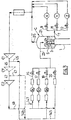
- Figure 1 represents a capacity and a column according to the invention
- Figures 2 to 4 schematically represent apparatus for producing carbon monoxide by cryogenic separation according to the invention.
- a column 1 is surmounted by a head condenser 3 fed with a gas overhead of the column. This gas condenses at least partially in the condenser 3 and is returned to the top of the column.
- the condenser 3 is surrounded by a cylindrical barrier 5 sealingly attached to the bottom of a cylindrical chamber 21 enclosing the condenser.
- the barrier and the enclosure are substantially concentric with the condenser 3.
- the barrier 5 is lower than the enclosure 21.
- the barrier may comprise cutouts at the top of the wall for the passage of liquid.
- the barrier divides the enclosure into two parts A and B, the first part A being between the condenser and the barrier 5 and the second part B being located between the barrier 5 and the wall of the enclosure 21.
- Pipes 15, 17, 19 feed the first part A and a pipe 7 is attached to the second part B, then being divided into lines 9, 11.
- the condenser In use, the condenser is fed with liquid from at least one of the lines 15, 17, 19. This liquid is partially vaporized and the vapor thus formed is withdrawn from the chamber 21. When the liquid level reached the top of the barrier 5, the collected liquid overflows and falls in the second part B.
- the illustrated capacity functions as described above and has the same structure as that described for the Figure 1 .
- the process of Figure 2 is a methane scrubbing process comprising a K01 methane scrubbing column, a K02 depletion column, a carbon monoxide and KO3 methane separation column and a KO4 carbon monoxide and nitrogen separation column.
- the flows fed to the columns and produced by the columns are not illustrated for the sake of simplification.
- the method could include fewer columns or more columns.
- the separation column of carbon monoxide and nitrogen is not an essential element of the invention.
- the K01 column is fed with a feed rate
- a fluid of the hydrogen depleted column is sent to the K02 exhaust column
- the bottom liquid of the exhaust column is sent to the CO separation column.
- CH 4 K03 and the column K04 is fed with a fluid from column K03, allowing the production of pure carbon monoxide in the bottom of column K04.
- the capacitor C is fed with a liquid 21 coming from at least two different sources but having substantially the same composition. This liquid is rich in carbon monoxide.
- the liquid 15 sent in the first part of the chamber comes from the reboiler Q6 of the exhaust column K02.
- the liquid 17 sent in the first part of the chamber comes from the reboiler Q7 of a carbon monoxide and methane separation column.
- the liquid 19 sent in the first part of the chamber comes from the exchanger 49.
- the liquid overflowing over the barrier is divided into three parts.
- Part X is sent via 7A and 9 to a cooling exchanger of the washing column K01.
- Part Y is sent via 7A and 11 to a pot 41 and then to the main exchange line where the mixture feeding the apparatus cools.
- Part 12 is sent to the head condenser Z of the CO / nitrogen separation column K04.
- Part X evaporates in the cooling exchanger to form a flow 39. It is mixed with the vaporized flow rates 25, 37 from the condensers of column K03 and column K04 respectively.
- the mixed flow 43 joins the overhead gas of the separator pot 41 and heats up in the exchanger 51.
- This flow 43 is compressed by a compressor C1.
- a compressed portion 45 is sent to the exchanger 49 and then is divided, the portion 31 feeding the column K04 and the remainder constituting the flow 19.
- the remainder of the flow 43 is compressed in the compressor C2 to form part of the flow 47 which, cooled in the exchanger 51, becomes the flow 15 for the capacity C.
- the compressor C3 compresses the rest of the flow to form the flow 49 which is divided in two. Part of the flow mixes with flow 47 and the remainder becomes flow 17.
- the illustrated capacity functions as described above and has the same structure as that described for the Figure 1 .
- the process of Figure 3 may be a partial condensation or methane scrubbing process comprising at least one depletion column, a carbon monoxide and methane separation column and a carbon monoxide and nitrogen separation column.
- the apparatus comprises a methane scrubbing column.
- the capacitor C is fed with a liquid 23 coming from at least two different sources but having substantially the same composition.
- This liquid may for example be a liquid rich in carbon monoxide, rich in nitrogen or a mixture containing mainly hydrogen and carbon monoxide.
- the liquid 15 sent in the first part of the chamber comes from the reboiler Q6 of a depletion column.
- the liquid 17 sent in the first part of the chamber comes from the reboiler Q7 of a carbon monoxide and methane separation column.
- the liquid 19 sent to the first part of the enclosure comes from the reboiler Q8 of a carbon monoxide and nitrogen separation column, if there is one.
- the liquid 7 having overflowed over the barrier is divided into three parts 9, 11, 12.
- the part 9 is sent to a cooling exchanger X of a washing column, if there is one.
- Part 11 is sent to the main exchange line Y where the mixture feeding the apparatus cools.
- Part 12 is sent to the head condenser Z of a column other than column 1, for example a carbon monoxide and nitrogen separation column, such as column K04 of the Figure 2 .
- Each of these portions 9, 11, 12 vaporizes and is mixed with the vaporized liquid from the condenser 3.
- the mixed flow forms a cycle gas which is compressed in a multi-stage compressor, called C1, C1 'and C2 compressors. , connected in series.
- the compressor Cl compressed the gas to form a flow 45 which becomes the flow 19 downstream of the reboiler Q8.
- the compressor C2 produces a flow 49 which feeds the reboilers Q6, Q7, the remainder 145 forming the flow 20 is also sent to the condenser 3.
- the method of the Figure 4 represents a process for producing carbon monoxide and hydrogen by partial condensation.
- the apparatus comprises a separator pot 405, a depletion column 411 and a carbon monoxide and nitrogen separation column 1.
- Column 1 comprises a storage capacity according to the invention.
- Part of the synthesis gas is used to reboil the depletion column 411 by means of the reboiler 405.
- the gas of The partially condensed synthesis exits the exchange line 403 and is sent to the separator pot 405.
- the overhead gas 407 heats up in the exchange line and serves as a hydrogen-rich product.
- the liquid 409 is sent to the top of the depletion column 411.
- the overhead gas 410 of the depletion column 411 leaves the apparatus after heating in the exchange line 403.
- the tank liquid 415 of the column depletion 411 is sent to an intermediate point of the exchange line 403 where it cools and is divided into two.
- Part 419 is sent to separation column 1 after expansion.
- the remainder 417 heats up in the exchange line and is sent to the separation column 1 at a lower level.
- the tank liquid 449 of the separation column 1 is sent to the head condenser thereof where it partially vaporizes.
- the vaporized liquid rich in carbon monoxide 425 is sent to the exchange line 403 to heat up and then to the compressor C1.
- Carbon monoxide is cooled with water.
- a portion 453 serves as a product after a compression step in the compressor C2.
- the rest 451 cools in the exchange line.
- a portion 431 is expanded in a turbine T to provide frigories at separation and recycled to the compressor C1.
- the rest 433 is divided in two.
- Part 435 is sent to an intermediate temperature of the exchange line 403 at the bottom of the column 1 and at the top condenser (flow 437) after cooling in the exchanger 451 against a flow of liquid nitrogen 441.
- the remains 453 is sent to the condenser at the temperature of the cold end of the exchange line 403.
- the compressed cycle gas in the compressor C1 may be a carbon monoxide rich gas, a nitrogen rich gas, or a gaseous mixture of hydrogen and carbon monoxide.
Landscapes
- Engineering & Computer Science (AREA)
- Physics & Mathematics (AREA)
- Mechanical Engineering (AREA)
- Thermal Sciences (AREA)
- General Engineering & Computer Science (AREA)
- Separation By Low-Temperature Treatments (AREA)
- Carbon And Carbon Compounds (AREA)
Claims (14)
- Gerät zur Herstellung mindestens eines Fluids durch kryogene Trennung, umfassend eine Destillationskolonne,wobei die Kolonne eine Flüssigkeitsspeicherkapazität (C) aufweist, wobei die Flüssigkeitsspeicherkapazität (C) ein Gehäuse (21), einen innerhalb des Gehäuses angeordneten Wärmetauscher (3), eine Sperre (5), die das Gehäuse in zwei Teile unterteilt, wobei sich der Wärmetauscher in dem ersten Teil (A) befindet, und wobei der zweite Teil (B) um den ersten Teil herum angeordnet ist, wobei die Sperre eine Höhe hat, die zumindest an bestimmten Punkten geringer als die Höhe des Gehäuses ist, um den Durchgang von Flüssigkeit von dem ersten Teil zu dem zweiten Teil über die Sperre zu ermöglichen, wenn die Kapazität im Dienst ist, und gegebenenfalls auf dichte Weise am Boden des Gefäßes befestigt ist, Mittel (15, 17, 19) zum Leiten der Flüssigkeit zu dem Inneren des ersten Teils des Gehäuses sowie Mittel (7) zum Entnehmen der Flüssigkeit aus dem zweiten Teil des Gehäuses und Mittel zum Leiten eines Fluids zu dem Austauscher und zum Entnehmen eines Fluids aus dem Austauscher umfasst, wobei der Austauscher ein Verdampfungssumpf oder ein Kopfkondensator ist,dadurch gekennzeichnet, dass das Gerät ein Gerät zur Herstellung von Kohlenmonoxid- und/oder Wasserstoff ist, und dass die Kolonne eine Kolonne zur Trennung von Kohlenmonoxid und Methan (K03) oder eine Kolonne zur Trennung von Kohlenmonoxid und Stickstoff (K04) ist.
- Gerät nach Anspruch 1, umfassend Mittel (15, 17, 19, 449, 451, 453) zum Leiten von der Flüssigkeit zu dem Inneren des ersten Teils, die aus mindestens zwei verschiedenen Quellen stammt, und/oder Mittel (7, 7A, 11, 12) zum Entnehmen von der Flüssigkeit aus dem zweiten Teil und anschließenden Leiten derselben an zwei verschiedene Bestimmungsorte.
- Gerät nach Anspruch 2, umfassend eine Waschkolonne (K01) und Mittel zum Leiten der entnommenen Flüssigkeit zumindest zu dem Kühler (X) der Waschkolonne.
- Gerät nach Anspruch 2 oder 3, umfassend eine Austauschleitung (51), Mittel zum Leiten von dem Fluid zur Versorgung des Geräts zu der Austauschleitung, um es dort zu kühlen, und Mittel (11) zum Leiten der entnommenen Flüssigkeit zumindest zu der Austauschleitung.
- Gerät nach Anspruch 2, 3 oder 4, umfassend Mittel zum Leiten der entnommenen Flüssigkeit mindestens zu einem Kondensator des Kopfs der Kolonne zur Trennung von Kohlenmonoxid und Methan oder der Kolonne zur Trennung von Kohlenmonoxid und Stickstoff.
- Gerät nach Anspruch 2, umfassend eine Entleerungskolonne (K02, 411, 511), die einen Verdampfungssumpf und Mittel (15) zum Leiten der kondensierten Flüssigkeit in den Verdampfungssumpf zu dem ersten Teil der Kapazität hat.
- Gerät nach einem der Ansprüche 2 bis 6, umfassend eine Kolonne zur Trennung von Kohlenmonoxid und Stickstoffmonoxid (K04), die einen Verdampfungssumpf und Mittel zum Leiten der kondensierten Flüssigkeit zu dem Verdampfungssumpf in dem ersten Teil der Kapazität hat.
- Gerät nach einem der Ansprüche 2 bis 7, umfassend eine Kolonne zur Trennung von Kohlenmonoxid und Methan (1), die einem Verdampfungssumpf (521) und Mittel (17) zum Leiten der kondensierten Flüssigkeit in den Verdampfungssumpf zu dem ersten Teil der Kapazität hat.
- Gerät nach einem der Ansprüche 2 bis 8, umfassend eine Austauschleitung (51, 403, 503) und Mittel (435, 437, 535, 537), um eine Flüssigkeit von der Austauschleitung zu dem ersten Teil der Kapazität zu leiten.
- Gerät nach Anspruch 1, wobei die Sperre eine im Wesentlichen zylindrische Form hat.
- Gerät nach Anspruch 1, wobei die Sperre koaxial zu dem Gehäuse ist.
- Verfahren zur Herstellung von Kohlenmonoxid und/oder Wasserstoff durch kryogene Trennung in einem Gerät nach Anspruch 1.
- Verfahren nach Anspruch 12, wobei die Flüssigkeit, die aus mindestens zwei verschiedenen Quellen stammt, in das Innere des ersten Teils geleitet wird.
- Verfahren nach Anspruch 12 oder 13, wobei die Flüssigkeit aus dem zweiten Teil entnommen wird, um sie dann an zwei verschiedene Bestimmungsorte zu schicken.
Applications Claiming Priority (2)
| Application Number | Priority Date | Filing Date | Title |
|---|---|---|---|
| FR0755165A FR2916523B1 (fr) | 2007-05-21 | 2007-05-21 | Capacite de stockage, appareil et procede de production de monoxyde de carbone et/ou d'hydrogene par separation cryogenique integrant une telle capacite. |
| PCT/FR2008/050843 WO2008142349A2 (fr) | 2007-05-21 | 2008-05-16 | Capacite de stockage, appareil et procede de production de monoxyde de carbone et/ou d'hydrogene par separation cryogenique integrant une telle capacite |
Publications (2)
| Publication Number | Publication Date |
|---|---|
| EP2149021A2 EP2149021A2 (de) | 2010-02-03 |
| EP2149021B1 true EP2149021B1 (de) | 2018-07-25 |
Family
ID=39203232
Family Applications (1)
| Application Number | Title | Priority Date | Filing Date |
|---|---|---|---|
| EP08805790.6A Active EP2149021B1 (de) | 2007-05-21 | 2008-05-16 | Aufbewahrungsgehäuse, verfahren und vorrichtung zur herstellung von kohlenmonoxid und/oder wasserstoff durch kryogene trennung, einschliesslich solch eines gehäuses |
Country Status (4)
| Country | Link |
|---|---|
| US (1) | US8783062B2 (de) |
| EP (1) | EP2149021B1 (de) |
| FR (1) | FR2916523B1 (de) |
| WO (1) | WO2008142349A2 (de) |
Families Citing this family (7)
| Publication number | Priority date | Publication date | Assignee | Title |
|---|---|---|---|---|
| FR2930332A1 (fr) * | 2008-04-18 | 2009-10-23 | Air Liquide | Procede et appareil de separation cryogenique d'un melange d'hydrogene et de monoxyde de carbone |
| EP2562502A1 (de) * | 2011-06-24 | 2013-02-27 | L'air Liquide, Societe Anonyme Pour L'etude Et L'exploitation Des Procedes Georges Claude | Verfahren und Installation zur Bereitstellung eines gasförmigen Kohlenstoffmonoxids durch kryogene Destillation |
| EP2662652A1 (de) * | 2012-05-07 | 2013-11-13 | L'air Liquide, Societe Anonyme Pour L'etude Et L'exploitation Des Procedes Georges Claude | Verfahren und Vorrichtung zur Trennung einer Mischung aus Methan, Kohlenstoffdioxid und Wasserstoff durch kryogene Destillation |
| FR3013107A1 (fr) * | 2013-11-14 | 2015-05-15 | Air Liquide | Procede et appareil de deazotation d’un fluide riche en monoxyde de carbone |
| CN103868324B (zh) * | 2014-03-07 | 2015-10-14 | 上海交通大学 | 小型撬装式混合制冷剂天然气液化和ngl回收一体系统 |
| FR3075067B1 (fr) * | 2017-12-14 | 2020-08-28 | Air Liquide | Procede et appareil de separation cryogenique d'un gaz de synthese contenant une etape de separation de l'azote |
| FR3148592A1 (fr) | 2023-05-11 | 2024-11-15 | L'air Liquide, Societe Anonyme Pour L'etude Et L'exploitation Des Procedes Georges Claude | Procédé et appareil de production de monoxyde de carbone |
Family Cites Families (25)
| Publication number | Priority date | Publication date | Assignee | Title |
|---|---|---|---|---|
| US2044372A (en) * | 1934-10-26 | 1936-06-16 | Lee S Twomey | Reboiler and condenser |
| US3082134A (en) * | 1958-07-10 | 1963-03-19 | Specialties Dev Corp | Hollow articles and method of making the same |
| DE1792285A1 (de) | 1968-08-14 | 1971-10-28 | Linde Ag | Verfahren und Vorrichtung zur Erzeugung und Reinigung von Wasserstoff |
| DE3215829A1 (de) * | 1982-04-28 | 1983-11-03 | Linde Ag, 6200 Wiesbaden | Verfahren zur gewinnung von kohlenmonoxid |
| JPS60253782A (ja) * | 1984-05-30 | 1985-12-14 | 日本酸素株式会社 | 大型空気分離装置用凝縮器 |
| JPH0789012B2 (ja) * | 1986-12-26 | 1995-09-27 | 大同ほくさん株式会社 | 一酸化炭素分離精製装置 |
| DE3739724A1 (de) | 1987-11-24 | 1989-06-08 | Linde Ag | Verfahren und vorrichtung zum zerlegen eines gasgemisches |
| DE3741906A1 (de) | 1987-12-10 | 1989-06-22 | Linde Ag | Verfahren zur gewinnung von h(pfeil abwaerts)2(pfeil abwaerts) und co |
| FR2650379B1 (fr) * | 1989-07-28 | 1991-10-18 | Air Liquide | Appareil de vaporisation-condensation pour double colonne de distillation d'air, et installation de distillation d'air comportant un tel appareil |
| FR2664263B1 (fr) | 1990-07-04 | 1992-09-18 | Air Liquide | Procede et installation de production simultanee de methane et monoxyde de carbone. |
| FR2681131A1 (fr) | 1991-09-11 | 1993-03-12 | Air Liquide | Procede et installation de production de monoxyde de carbone et d'hydrogene. |
| DE4406049A1 (de) * | 1994-02-24 | 1995-09-07 | Linde Ag | Verfahren und Vorrichtung zur Gewinnung von reinem Argon |
| JP3368326B2 (ja) * | 1994-04-04 | 2003-01-20 | 日揮株式会社 | 熱交換装置及び多段熱交換装置 |
| DE4433114A1 (de) | 1994-09-16 | 1996-03-21 | Linde Ag | Verfahren zum Gewinnen einer Kohlenmonoxid-Reinfraktion |
| US5617742A (en) * | 1996-04-30 | 1997-04-08 | The Boc Group, Inc. | Distillation apparatus |
| GB9715983D0 (en) | 1997-07-29 | 1997-10-01 | Air Prod & Chem | Process and apparatus for seperating a gaseous mixture |
| GB9800693D0 (en) | 1998-01-13 | 1998-03-11 | Air Prod & Chem | Separation of carbon monoxide from nitrogen-contaminated gaseous mixtures |
| GB9800692D0 (en) | 1998-01-13 | 1998-03-11 | Air Prod & Chem | Separation of carbon monoxide from nitrogen-contaminated gaseous mixtures also containing hydrogen and methane |
| WO1999039143A1 (de) * | 1998-01-30 | 1999-08-05 | Linde Aktiengesellschaft | Verfahren und vorrichtung zum verdampfen von flüssigem sauerstoff |
| GB9807797D0 (en) | 1998-04-09 | 1998-06-10 | Air Prod & Chem | Separation of carbon monoxide from gaseous mixtures containing carbon monoxide and hydrogen |
| GB9918420D0 (en) | 1999-08-04 | 1999-10-06 | Air Prod & Chem | Process and apparatus for separating mixtures of hydrogen and carbon monoxide |
| US6726747B2 (en) | 2001-03-21 | 2004-04-27 | American Air Liquide | Methods and apparatuses for treatment of syngas and related gases |
| FR2853723B1 (fr) * | 2003-04-10 | 2007-03-30 | Air Liquide | Procede et installation de traitement d'un bain de liquide riche en oxygene recueilli en pied d'une colonne de distillation cryogenique |
| PT1479989E (pt) * | 2003-05-19 | 2011-07-08 | Air Liquide | Processo e instalação para o fornecimento de monóxido de carbono gasoso e/ou uma mistura contendo monóxido de carbono |
| US7621152B2 (en) * | 2006-02-24 | 2009-11-24 | Praxair Technology, Inc. | Compact cryogenic plant |
-
2007
- 2007-05-21 FR FR0755165A patent/FR2916523B1/fr not_active Expired - Fee Related
-
2008
- 2008-05-16 WO PCT/FR2008/050843 patent/WO2008142349A2/fr not_active Ceased
- 2008-05-16 EP EP08805790.6A patent/EP2149021B1/de active Active
- 2008-05-16 US US12/600,961 patent/US8783062B2/en active Active
Non-Patent Citations (1)
| Title |
|---|
| None * |
Also Published As
| Publication number | Publication date |
|---|---|
| US20100199718A1 (en) | 2010-08-12 |
| FR2916523A1 (fr) | 2008-11-28 |
| WO2008142349A2 (fr) | 2008-11-27 |
| WO2008142349A3 (fr) | 2013-07-18 |
| FR2916523B1 (fr) | 2014-12-12 |
| EP2149021A2 (de) | 2010-02-03 |
| US8783062B2 (en) | 2014-07-22 |
Similar Documents
| Publication | Publication Date | Title |
|---|---|---|
| EP2149021B1 (de) | Aufbewahrungsgehäuse, verfahren und vorrichtung zur herstellung von kohlenmonoxid und/oder wasserstoff durch kryogene trennung, einschliesslich solch eines gehäuses | |
| EP0676373B1 (de) | Verfahren und Anlage zur Herstellung von Kohlenmonoxyd | |
| EP2137474B1 (de) | Verfahren und vorrichtung zur herstellung von kohlenmonoxid durch kryogene destillation | |
| WO2013135993A2 (fr) | Procédé et appareil de séparation d'un mélange contenant du dioxyde de carbone par distillation | |
| EP0968959A1 (de) | Verfahren zur Herstellung von Kohlenmonoxid | |
| FR2880418A1 (fr) | Ensemble d'echangeurs de chaleur, appareil de distillation cryogenique incorporant un tel ensemble et procede de distillation cryogenique utilisant un tel ensemble | |
| EP2542844B1 (de) | Vorrichtung und verfahren zur destillativen trennung einer kohlendioxid enthaltenden mischung | |
| EP3599438A1 (de) | Verfahren und gerät zur kryogenen trennung eines gemischs aus kohlenmonoxid, wasserstoff und methan für die herstellung von ch4 | |
| EP3812675B1 (de) | Verfahren und anlage zur luftzerlegung durch kryogene destillation | |
| FR2837564A1 (fr) | Procede et installation de production d'oxygene et/ou d'azote sous pression et d'argon pur | |
| EP1966554B1 (de) | Lufttrennvorrichtung durch kryogenische destillation | |
| WO2005033599A1 (fr) | Procede et installation de production de monoxyde de carbone par distillation cryogenique | |
| WO2022175204A1 (fr) | Procédé et appareil de liquéfaction d'hydrogène | |
| EP3542112B1 (de) | Verfahren und anlage zur kryogenen trennung eines gasgemisches durch methanwäsche | |
| WO2018104598A1 (fr) | Procédé et appareil intégrés de séparation d'air par distillation cryogénique et de refroidissement d'un gaz | |
| EP0884543A1 (de) | Verfahren und Anlage zur Lufttrennung durch kryogene Destillation | |
| WO2022162041A1 (fr) | Procédé et appareil de séparation d'un débit riche en dioxyde de carbone par distillation pour produire du dioxyde de carbone liquide | |
| FR3120431A1 (fr) | Purification de monoxyde de carbone par distillation cryogénique | |
| WO2026074075A1 (fr) | Procédé et appareil de séparation d'air par distillation cryogénique | |
| EP1690053A1 (de) | Verfahren und vorrichtung zum trennen von luft durch kryogene destillation | |
| EP3913310A1 (de) | Verfahren und gerät zur trennung von luft durch kryogene destillation | |
| WO2009130430A2 (fr) | Procede et appareil de separation d'air par distillation cryogenique | |
| FR2910603A1 (fr) | Procede de separation d'un melange de monoxyde de carbone, de methane, d'hydrogene et eventuellement d'azote par distillation cryogenetique | |
| FR2987755A1 (fr) | Procede et appareil de separation par distillation d'un gaz contenant du dioxyde de carbone | |
| WO2013114020A2 (fr) | Procédé et appareil de condensation ou de pseudocondensation d'un gaz |
Legal Events
| Date | Code | Title | Description |
|---|---|---|---|
| PUAI | Public reference made under article 153(3) epc to a published international application that has entered the european phase |
Free format text: ORIGINAL CODE: 0009012 |
|
| AK | Designated contracting states |
Kind code of ref document: A2 Designated state(s): AT BE BG CH CY CZ DE DK EE ES FI FR GB GR HR HU IE IS IT LI LT LU LV MC MT NL NO PL PT RO SE SI SK TR |
|
| AX | Request for extension of the european patent |
Extension state: AL BA MK RS |
|
| DAX | Request for extension of the european patent (deleted) | ||
| R17D | Deferred search report published (corrected) |
Effective date: 20130718 |
|
| 17P | Request for examination filed |
Effective date: 20140120 |
|
| RBV | Designated contracting states (corrected) |
Designated state(s): AT BE BG CH CY CZ DE DK EE ES FI FR GB GR HR HU IE IS IT LI LT LU LV MC MT NL NO PL PT RO SE SI SK TR |
|
| GRAP | Despatch of communication of intention to grant a patent |
Free format text: ORIGINAL CODE: EPIDOSNIGR1 |
|
| STAA | Information on the status of an ep patent application or granted ep patent |
Free format text: STATUS: GRANT OF PATENT IS INTENDED |
|
| INTG | Intention to grant announced |
Effective date: 20180327 |
|
| GRAS | Grant fee paid |
Free format text: ORIGINAL CODE: EPIDOSNIGR3 |
|
| GRAA | (expected) grant |
Free format text: ORIGINAL CODE: 0009210 |
|
| STAA | Information on the status of an ep patent application or granted ep patent |
Free format text: STATUS: THE PATENT HAS BEEN GRANTED |
|
| AK | Designated contracting states |
Kind code of ref document: B1 Designated state(s): AT BE BG CH CY CZ DE DK EE ES FI FR GB GR HR HU IE IS IT LI LT LU LV MC MT NL NO PL PT RO SE SI SK TR |
|
| REG | Reference to a national code |
Ref country code: GB Ref legal event code: FG4D Free format text: NOT ENGLISH |
|
| REG | Reference to a national code |
Ref country code: CH Ref legal event code: EP |
|
| REG | Reference to a national code |
Ref country code: AT Ref legal event code: REF Ref document number: 1022213 Country of ref document: AT Kind code of ref document: T Effective date: 20180815 |
|
| REG | Reference to a national code |
Ref country code: IE Ref legal event code: FG4D Free format text: LANGUAGE OF EP DOCUMENT: FRENCH |
|
| REG | Reference to a national code |
Ref country code: DE Ref legal event code: R096 Ref document number: 602008056161 Country of ref document: DE |
|
| REG | Reference to a national code |
Ref country code: NL Ref legal event code: FP |
|
| REG | Reference to a national code |
Ref country code: LT Ref legal event code: MG4D |
|
| REG | Reference to a national code |
Ref country code: AT Ref legal event code: MK05 Ref document number: 1022213 Country of ref document: AT Kind code of ref document: T Effective date: 20180725 |
|
| PG25 | Lapsed in a contracting state [announced via postgrant information from national office to epo] |
Ref country code: IS Free format text: LAPSE BECAUSE OF FAILURE TO SUBMIT A TRANSLATION OF THE DESCRIPTION OR TO PAY THE FEE WITHIN THE PRESCRIBED TIME-LIMIT Effective date: 20181125 Ref country code: FI Free format text: LAPSE BECAUSE OF FAILURE TO SUBMIT A TRANSLATION OF THE DESCRIPTION OR TO PAY THE FEE WITHIN THE PRESCRIBED TIME-LIMIT Effective date: 20180725 Ref country code: GR Free format text: LAPSE BECAUSE OF FAILURE TO SUBMIT A TRANSLATION OF THE DESCRIPTION OR TO PAY THE FEE WITHIN THE PRESCRIBED TIME-LIMIT Effective date: 20181026 Ref country code: NO Free format text: LAPSE BECAUSE OF FAILURE TO SUBMIT A TRANSLATION OF THE DESCRIPTION OR TO PAY THE FEE WITHIN THE PRESCRIBED TIME-LIMIT Effective date: 20181025 Ref country code: SE Free format text: LAPSE BECAUSE OF FAILURE TO SUBMIT A TRANSLATION OF THE DESCRIPTION OR TO PAY THE FEE WITHIN THE PRESCRIBED TIME-LIMIT Effective date: 20180725 Ref country code: BG Free format text: LAPSE BECAUSE OF FAILURE TO SUBMIT A TRANSLATION OF THE DESCRIPTION OR TO PAY THE FEE WITHIN THE PRESCRIBED TIME-LIMIT Effective date: 20181025 Ref country code: AT Free format text: LAPSE BECAUSE OF FAILURE TO SUBMIT A TRANSLATION OF THE DESCRIPTION OR TO PAY THE FEE WITHIN THE PRESCRIBED TIME-LIMIT Effective date: 20180725 Ref country code: LT Free format text: LAPSE BECAUSE OF FAILURE TO SUBMIT A TRANSLATION OF THE DESCRIPTION OR TO PAY THE FEE WITHIN THE PRESCRIBED TIME-LIMIT Effective date: 20180725 Ref country code: PL Free format text: LAPSE BECAUSE OF FAILURE TO SUBMIT A TRANSLATION OF THE DESCRIPTION OR TO PAY THE FEE WITHIN THE PRESCRIBED TIME-LIMIT Effective date: 20180725 |
|
| PG25 | Lapsed in a contracting state [announced via postgrant information from national office to epo] |
Ref country code: HR Free format text: LAPSE BECAUSE OF FAILURE TO SUBMIT A TRANSLATION OF THE DESCRIPTION OR TO PAY THE FEE WITHIN THE PRESCRIBED TIME-LIMIT Effective date: 20180725 Ref country code: LV Free format text: LAPSE BECAUSE OF FAILURE TO SUBMIT A TRANSLATION OF THE DESCRIPTION OR TO PAY THE FEE WITHIN THE PRESCRIBED TIME-LIMIT Effective date: 20180725 Ref country code: ES Free format text: LAPSE BECAUSE OF FAILURE TO SUBMIT A TRANSLATION OF THE DESCRIPTION OR TO PAY THE FEE WITHIN THE PRESCRIBED TIME-LIMIT Effective date: 20180725 |
|
| REG | Reference to a national code |
Ref country code: DE Ref legal event code: R097 Ref document number: 602008056161 Country of ref document: DE |
|
| PG25 | Lapsed in a contracting state [announced via postgrant information from national office to epo] |
Ref country code: CZ Free format text: LAPSE BECAUSE OF FAILURE TO SUBMIT A TRANSLATION OF THE DESCRIPTION OR TO PAY THE FEE WITHIN THE PRESCRIBED TIME-LIMIT Effective date: 20180725 Ref country code: RO Free format text: LAPSE BECAUSE OF FAILURE TO SUBMIT A TRANSLATION OF THE DESCRIPTION OR TO PAY THE FEE WITHIN THE PRESCRIBED TIME-LIMIT Effective date: 20180725 Ref country code: EE Free format text: LAPSE BECAUSE OF FAILURE TO SUBMIT A TRANSLATION OF THE DESCRIPTION OR TO PAY THE FEE WITHIN THE PRESCRIBED TIME-LIMIT Effective date: 20180725 Ref country code: IT Free format text: LAPSE BECAUSE OF FAILURE TO SUBMIT A TRANSLATION OF THE DESCRIPTION OR TO PAY THE FEE WITHIN THE PRESCRIBED TIME-LIMIT Effective date: 20180725 |
|
| PG25 | Lapsed in a contracting state [announced via postgrant information from national office to epo] |
Ref country code: DK Free format text: LAPSE BECAUSE OF FAILURE TO SUBMIT A TRANSLATION OF THE DESCRIPTION OR TO PAY THE FEE WITHIN THE PRESCRIBED TIME-LIMIT Effective date: 20180725 Ref country code: SK Free format text: LAPSE BECAUSE OF FAILURE TO SUBMIT A TRANSLATION OF THE DESCRIPTION OR TO PAY THE FEE WITHIN THE PRESCRIBED TIME-LIMIT Effective date: 20180725 |
|
| PLBE | No opposition filed within time limit |
Free format text: ORIGINAL CODE: 0009261 |
|
| STAA | Information on the status of an ep patent application or granted ep patent |
Free format text: STATUS: NO OPPOSITION FILED WITHIN TIME LIMIT |
|
| 26N | No opposition filed |
Effective date: 20190426 |
|
| PG25 | Lapsed in a contracting state [announced via postgrant information from national office to epo] |
Ref country code: SI Free format text: LAPSE BECAUSE OF FAILURE TO SUBMIT A TRANSLATION OF THE DESCRIPTION OR TO PAY THE FEE WITHIN THE PRESCRIBED TIME-LIMIT Effective date: 20180725 |
|
| REG | Reference to a national code |
Ref country code: CH Ref legal event code: PL |
|
| PG25 | Lapsed in a contracting state [announced via postgrant information from national office to epo] |
Ref country code: LI Free format text: LAPSE BECAUSE OF NON-PAYMENT OF DUE FEES Effective date: 20190531 Ref country code: CH Free format text: LAPSE BECAUSE OF NON-PAYMENT OF DUE FEES Effective date: 20190531 Ref country code: MC Free format text: LAPSE BECAUSE OF FAILURE TO SUBMIT A TRANSLATION OF THE DESCRIPTION OR TO PAY THE FEE WITHIN THE PRESCRIBED TIME-LIMIT Effective date: 20180725 |
|
| PG25 | Lapsed in a contracting state [announced via postgrant information from national office to epo] |
Ref country code: LU Free format text: LAPSE BECAUSE OF NON-PAYMENT OF DUE FEES Effective date: 20190516 |
|
| PG25 | Lapsed in a contracting state [announced via postgrant information from national office to epo] |
Ref country code: TR Free format text: LAPSE BECAUSE OF FAILURE TO SUBMIT A TRANSLATION OF THE DESCRIPTION OR TO PAY THE FEE WITHIN THE PRESCRIBED TIME-LIMIT Effective date: 20180725 |
|
| PG25 | Lapsed in a contracting state [announced via postgrant information from national office to epo] |
Ref country code: IE Free format text: LAPSE BECAUSE OF NON-PAYMENT OF DUE FEES Effective date: 20190516 |
|
| PG25 | Lapsed in a contracting state [announced via postgrant information from national office to epo] |
Ref country code: PT Free format text: LAPSE BECAUSE OF FAILURE TO SUBMIT A TRANSLATION OF THE DESCRIPTION OR TO PAY THE FEE WITHIN THE PRESCRIBED TIME-LIMIT Effective date: 20181125 |
|
| PG25 | Lapsed in a contracting state [announced via postgrant information from national office to epo] |
Ref country code: CY Free format text: LAPSE BECAUSE OF FAILURE TO SUBMIT A TRANSLATION OF THE DESCRIPTION OR TO PAY THE FEE WITHIN THE PRESCRIBED TIME-LIMIT Effective date: 20180725 |
|
| PG25 | Lapsed in a contracting state [announced via postgrant information from national office to epo] |
Ref country code: MT Free format text: LAPSE BECAUSE OF FAILURE TO SUBMIT A TRANSLATION OF THE DESCRIPTION OR TO PAY THE FEE WITHIN THE PRESCRIBED TIME-LIMIT Effective date: 20180725 Ref country code: HU Free format text: LAPSE BECAUSE OF FAILURE TO SUBMIT A TRANSLATION OF THE DESCRIPTION OR TO PAY THE FEE WITHIN THE PRESCRIBED TIME-LIMIT; INVALID AB INITIO Effective date: 20080516 |
|
| P01 | Opt-out of the competence of the unified patent court (upc) registered |
Effective date: 20230523 |
|
| PGFP | Annual fee paid to national office [announced via postgrant information from national office to epo] |
Ref country code: NL Payment date: 20250521 Year of fee payment: 18 |
|
| PGFP | Annual fee paid to national office [announced via postgrant information from national office to epo] |
Ref country code: DE Payment date: 20250521 Year of fee payment: 18 |
|
| PGFP | Annual fee paid to national office [announced via postgrant information from national office to epo] |
Ref country code: GB Payment date: 20250521 Year of fee payment: 18 |
|
| PGFP | Annual fee paid to national office [announced via postgrant information from national office to epo] |
Ref country code: BE Payment date: 20250521 Year of fee payment: 18 |
|
| PGFP | Annual fee paid to national office [announced via postgrant information from national office to epo] |
Ref country code: FR Payment date: 20250528 Year of fee payment: 18 |