EP2149451A1 - Verfahren und Vorrichtung zum Nähen der Klappen eines Wellpappkartons - Google Patents
Verfahren und Vorrichtung zum Nähen der Klappen eines Wellpappkartons Download PDFInfo
- Publication number
- EP2149451A1 EP2149451A1 EP09164850A EP09164850A EP2149451A1 EP 2149451 A1 EP2149451 A1 EP 2149451A1 EP 09164850 A EP09164850 A EP 09164850A EP 09164850 A EP09164850 A EP 09164850A EP 2149451 A1 EP2149451 A1 EP 2149451A1
- Authority
- EP
- European Patent Office
- Prior art keywords
- flap
- folding
- corrugated cardboard
- sheets
- cardboard box
- Prior art date
- Legal status (The legal status is an assumption and is not a legal conclusion. Google has not performed a legal analysis and makes no representation as to the accuracy of the status listed.)
- Withdrawn
Links
- 238000009958 sewing Methods 0.000 title claims abstract description 27
- 238000000034 method Methods 0.000 title claims description 18
- 230000007246 mechanism Effects 0.000 claims abstract description 36
- 230000002401 inhibitory effect Effects 0.000 description 19
- 238000002360 preparation method Methods 0.000 description 18
- 238000005452 bending Methods 0.000 description 10
- 238000010276 construction Methods 0.000 description 6
- 230000000694 effects Effects 0.000 description 5
- 230000001360 synchronised effect Effects 0.000 description 5
- 230000032258 transport Effects 0.000 description 5
- NJPPVKZQTLUDBO-UHFFFAOYSA-N novaluron Chemical compound C1=C(Cl)C(OC(F)(F)C(OC(F)(F)F)F)=CC=C1NC(=O)NC(=O)C1=C(F)C=CC=C1F NJPPVKZQTLUDBO-UHFFFAOYSA-N 0.000 description 4
- 239000000835 fiber Substances 0.000 description 3
- 238000004026 adhesive bonding Methods 0.000 description 2
- 238000001035 drying Methods 0.000 description 1
- 230000007613 environmental effect Effects 0.000 description 1
- 238000010438 heat treatment Methods 0.000 description 1
- 238000004519 manufacturing process Methods 0.000 description 1
- 239000000463 material Substances 0.000 description 1
- 239000000725 suspension Substances 0.000 description 1
- 239000004753 textile Substances 0.000 description 1
Images




Classifications
-
- B—PERFORMING OPERATIONS; TRANSPORTING
- B31—MAKING ARTICLES OF PAPER, CARDBOARD OR MATERIAL WORKED IN A MANNER ANALOGOUS TO PAPER; WORKING PAPER, CARDBOARD OR MATERIAL WORKED IN A MANNER ANALOGOUS TO PAPER
- B31F—MECHANICAL WORKING OR DEFORMATION OF PAPER, CARDBOARD OR MATERIAL WORKED IN A MANNER ANALOGOUS TO PAPER
- B31F1/00—Mechanical deformation without removing material, e.g. in combination with laminating
- B31F1/20—Corrugating; Corrugating combined with laminating to other layers
- B31F1/24—Making webs in which the channel of each corrugation is transverse to the web feed
- B31F1/26—Making webs in which the channel of each corrugation is transverse to the web feed by interengaging toothed cylinders cylinder constructions
- B31F1/28—Making webs in which the channel of each corrugation is transverse to the web feed by interengaging toothed cylinders cylinder constructions combined with uniting the corrugated webs to flat webs ; Making double-faced corrugated cardboard
-
- B—PERFORMING OPERATIONS; TRANSPORTING
- B65—CONVEYING; PACKING; STORING; HANDLING THIN OR FILAMENTARY MATERIAL
- B65D—CONTAINERS FOR STORAGE OR TRANSPORT OF ARTICLES OR MATERIALS, e.g. BAGS, BARRELS, BOTTLES, BOXES, CANS, CARTONS, CRATES, DRUMS, JARS, TANKS, HOPPERS, FORWARDING CONTAINERS; ACCESSORIES, CLOSURES, OR FITTINGS THEREFOR; PACKAGING ELEMENTS; PACKAGES
- B65D5/00—Rigid or semi-rigid containers of polygonal cross-section, e.g. boxes, cartons or trays, formed by folding or erecting one or more blanks made of paper
- B65D5/42—Details of containers or of foldable or erectable container blanks
- B65D5/4279—Joints, seams, leakproof joints or corners, special connections between panels
- B65D5/4283—Connections formed by separate elements, e.g. clips, bands, straps
-
- B—PERFORMING OPERATIONS; TRANSPORTING
- B31—MAKING ARTICLES OF PAPER, CARDBOARD OR MATERIAL WORKED IN A MANNER ANALOGOUS TO PAPER; WORKING PAPER, CARDBOARD OR MATERIAL WORKED IN A MANNER ANALOGOUS TO PAPER
- B31B—MAKING CONTAINERS OF PAPER, CARDBOARD OR MATERIAL WORKED IN A MANNER ANALOGOUS TO PAPER
- B31B50/00—Making rigid or semi-rigid containers, e.g. boxes or cartons
- B31B50/60—Uniting opposed surfaces or edges; Taping
- B31B50/68—Uniting opposed surfaces or edges; Taping by stitching, stapling or riveting
- B31B50/684—Uniting opposed surfaces or edges; Taping by stitching, stapling or riveting for joining the overlapping edges of collapsed blanks to form tubular blanks
-
- B—PERFORMING OPERATIONS; TRANSPORTING
- B31—MAKING ARTICLES OF PAPER, CARDBOARD OR MATERIAL WORKED IN A MANNER ANALOGOUS TO PAPER; WORKING PAPER, CARDBOARD OR MATERIAL WORKED IN A MANNER ANALOGOUS TO PAPER
- B31F—MECHANICAL WORKING OR DEFORMATION OF PAPER, CARDBOARD OR MATERIAL WORKED IN A MANNER ANALOGOUS TO PAPER
- B31F1/00—Mechanical deformation without removing material, e.g. in combination with laminating
- B31F1/20—Corrugating; Corrugating combined with laminating to other layers
-
- B—PERFORMING OPERATIONS; TRANSPORTING
- B65—CONVEYING; PACKING; STORING; HANDLING THIN OR FILAMENTARY MATERIAL
- B65D—CONTAINERS FOR STORAGE OR TRANSPORT OF ARTICLES OR MATERIALS, e.g. BAGS, BARRELS, BOTTLES, BOXES, CANS, CARTONS, CRATES, DRUMS, JARS, TANKS, HOPPERS, FORWARDING CONTAINERS; ACCESSORIES, CLOSURES, OR FITTINGS THEREFOR; PACKAGING ELEMENTS; PACKAGES
- B65D5/00—Rigid or semi-rigid containers of polygonal cross-section, e.g. boxes, cartons or trays, formed by folding or erecting one or more blanks made of paper
- B65D5/32—Rigid or semi-rigid containers of polygonal cross-section, e.g. boxes, cartons or trays, formed by folding or erecting one or more blanks made of paper having bodies formed by folding and interconnecting two or more blanks
-
- B—PERFORMING OPERATIONS; TRANSPORTING
- B31—MAKING ARTICLES OF PAPER, CARDBOARD OR MATERIAL WORKED IN A MANNER ANALOGOUS TO PAPER; WORKING PAPER, CARDBOARD OR MATERIAL WORKED IN A MANNER ANALOGOUS TO PAPER
- B31B—MAKING CONTAINERS OF PAPER, CARDBOARD OR MATERIAL WORKED IN A MANNER ANALOGOUS TO PAPER
- B31B2105/00—Rigid or semi-rigid containers made by assembling separate sheets, blanks or webs
- B31B2105/002—Making boxes characterised by the shape of the blanks from which they are formed
- B31B2105/0022—Making boxes from tubular webs or blanks, e.g. with separate bottoms, including tube or bottom forming operations
-
- B—PERFORMING OPERATIONS; TRANSPORTING
- B31—MAKING ARTICLES OF PAPER, CARDBOARD OR MATERIAL WORKED IN A MANNER ANALOGOUS TO PAPER; WORKING PAPER, CARDBOARD OR MATERIAL WORKED IN A MANNER ANALOGOUS TO PAPER
- B31B—MAKING CONTAINERS OF PAPER, CARDBOARD OR MATERIAL WORKED IN A MANNER ANALOGOUS TO PAPER
- B31B50/00—Making rigid or semi-rigid containers, e.g. boxes or cartons
- B31B50/60—Uniting opposed surfaces or edges; Taping
Definitions
- the present invention relates to a method for bonding a connecting flap of a sheet for a corrugated cardboard box to another flap to be connected by thread-stitching and an apparatus therefor.
- the present invention concerns a sheet for a large-sized corrugated board box.
- it is directed to boding sheets for a corrugated cardboard box, which comprise one unit comprising one set of two sheets, split into two pieces.
- a conventional example of this type has adopted traditionally an apparatus and a method, so-called "wire-stitching", for bonding a connecting flap of one of two sheets in one unit for a corrugated cardboard box to a flap to be connected (hereafter referred to only as 'connected flap') of the other sheet (see Japanese Patent Publication No. Sho 52-29667 ).
- This conventional example discloses a method and an apparatus each of which feeds one sheet for a corrugated cardboard box to an upper guide bar and another sheet to a lower guide bar and bending the corrugated cardboard box sheets along preliminarily provided folding lines through the guide bars to provide a framework rectangular in section and then bond bonding portions, each of which comprises the connecting flap and the connected flap, sequentially by a wire stitcher.
- This conventional example bonds the bonding portion by a wire. Therefore when it is utilized for reuse, the existence of the wire becomes an obstacle to cause a trouble for removing it and besides when using it, the wire comes into contact with the human's body to damage it or the material to be packed. Further, the clothing's are not rarely damaged.
- the framework in rectangular in section is provided by bending the sheets along the folding lines through the guide bards.
- it is liable to lack reliability of the folding and preciseness as to the position-control of the framework.
- a sheet for corrugated cardboard box is manually bent into a shape rectangular in section through folding lines.
- a connecting flap is supported below a base pedestal and a connected flap is supported above the base pedestal to constitute a bonding portion, which consists of the connecting flap and the connected flap, vertically held with the base pedestal interposed therebetween.
- the bonding portion is stitched with threads such as staple fibers by moving a sewing-machine needle up and down, a sheet for corrugated cardboard box is extracted out of the base pedestal downwards of the sewing-machine needle and subsequently the bonding portion is thread-stitched.
- good valuation can be given to this example in that it has solved the problems the above-mentioned respective prior arts have suffers from.
- a sheet for a large-sized corrugated cardboard box for example, the sheet is 5,200 mm in length and 1,200 mm in width, and weights 4,100 g
- the load of the sheet is applied to a case housing a needle plate and a looper and as a result the needle plate and the case are bent or deformed to cause disorder in the relationship of position between the needle, the looper and the needle plate. This has degraded the reliability of the thread-stitching.
- the present invention has an object to provide a method and an apparatus for bonding a sheet for a large-sized corrugated cardboard box, which can ensure the reliability of folding so as to obtain the connecting flap and the connected-flap side sheet and can prevent the load of the sheet from being applied to the case housing the needle plate and the looper and inhibit the bending or deforming of the needle plate and the case as well as the disorder of the relationship of position between the needle, the looper and the needle plate.
- Another object is to provide a method and an apparatus generally usable for bonding purpose, which can attend in correspondence with every size of the sheet for corrugated cardboard box either large or small, on bonding the sheets for corrugated cardboard box either large or small, which is the theme of the present invention.
- a first means for solving the problem of the present invention is to provide a method for bonding the connecting flap and the connected flap of the sheet for corrugated cardboard box with threads. This method comprises:
- the first solution attempted not to expose the connecting flap in outer appearance by setting the connecting flap inside the connected flap. However, if the outer appearance is negligible, it is free to bend the connected flap inside the connecting flap to the contrary.
- a second means for solving the problems relates to an apparatus for bonding the sheet for corrugated cardboard box.
- This apparatus comprises an upper transporting means and a lower transporting means which vertically divide one set of two sheets for corrugated cardboard box to an upper one and a lower one and transporting them in a horizontal direction, in the one set of two sheets a connecting flap projecting on one side with a first folding line taken as a boundary and a connected flap corresponding to the connecting flap being formed on a rear surface of the other side, a second folding line being formed between the connecting flap and the connected flap, a connecting-flap side sheet being provided between the first folding line and the second folding line, the connected-flap side sheet being provided between the second folding line and the connected flap, an assembly which comprises an upper-position control means and a lower-position control means provided at the respective positions at least scheduled to be folded in the one set of sheets for the corrugated cardboard box, an upper connecting-flap folding means for folding the connecting flaps of the both sheets for the corrugated cardboard box with the respective first and
- the needle plates of the looper mechanisms are set inside the respective connecting flaps scheduled to be thread-stitched and the sewing-machine needle mechanisms are set outside the respective connected flaps scheduled to be thread-stitched. While the sewing-machine needle is synchronized with the intermittent movement of the intermittent moving means to reciprocally move it from the outside of the connected flap to the inside connecting flap in the horizontal direction, the threading portion, which comprises the connecting flap and the connected flap, is stitched with threads.
- the first solution to solve the problem of the present invention is constructed as above and therefore offers the following function and effect.
- one sheet for the corrugated cardboard box is arranged above in a horizontal state and the other sheet for the corrugated cardboard box is arranged below and symmetric with respect to one of the sheets for the corrugated cardboard box in the horizontal state and both of the above-mentioned sheets are maintained at their positions thus arranged;
- the connecting flap of one of the sheets for the corrugated cardboard box is bent at right angles inwards downwardly with the first folding line taken as a boundary and the connected-flap side sheet of the other sheet for the corrugated cardboard box is bent at right angles inwards upwardly with the second folding line taken as a boundary to form the position of the both sheets of the corrugated cardboard box into a shape rectangular in section; threading portions each of which comprises the connecting flap and the connected flap opposed to one another are set on a diagonal line and retain theirs positions as they are so set; two sets of sewing machines each of which comprise a sewing-machine needle mechanism provided with a sewing-machine needle movable in a horizontal direction and a looper mechanism having a needle plate
- both of the sheets which have their positions controlled in preparation for the thread-stitching step and besides are bent through the folding lines are formed into a rectangular shape in section.
- the threaded portions to be formed appear vertically in preparation for the thread-stitching step.
- the sheet for corrugated cardboard box on the side of the connected flap to be thread-stitched and the connecting flap are overlaid one on another in the horizontal direction. This has caused a likelihood that the load of the sheet is applied to the case which houses the needle plate and the looper to thereby bend or deform the needle plate and the case with the result of causing disorder in the relationship of position between the needle, the looper and the needle plate to reduce the reliability of the thread-stitching.
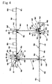
- the present invention has the subject matter to bond the sheets, in one unit, for a heavy corrugated cardboard box which weights as much as 2050g per sheet. Since the sheet for the corrugated cardboard box on the side of the connected flap and the connecting flap are restricted to such an extent that they are overlaid vertically one on another so as to hung down, their load is seldom applied to the looper mechanism side such as the case and the needle plate and therefore the reliability of the thread-stitching is expectable (see Fig. 4 ).
- the second means for solving the problem of the present invention is constituted as above and therefore offers the following function and effect.
- the upper position-control means and the lower position-control means are provided at the respective positions where they are scheduled to be folded.
- the assembly which comprises the upper connecting-flap side sheet folding means for folding the connecting flap with the first and second folding lines in each of the both sheets for the corrugated cardboard box taken as boundaries and the upper connected-flap side sheet folding means for folding the connected-flap and another assembly which comprises the lower connecting-flap folding means and the lower connected-flap side sheet folding means are arranged on a diagonal line and symmetric with respect to each other. Therefore, it is possible to bond the connecting flap and the connected-flap side sheet along the respective folding lines into an L-shape in section and an inversed L-shape in section while controlling their positions without allowing the both sheets to make the blind-movement.
- both of the sheets can be each formed rectangular in section in preparation for the thread-stitching and can be synchronized with the reciprocal movements of the sewing-machine needles by the upper intermittent moving means and the lower intermittent moving means so as to be stitched together with threads.
- the third solution is constituted as above and therefore offers the following function and effect.
- the upper transporting means, the upper connected-flap side sheet folding means for folding the connected-flap side sheet and the upper position-control means disposed near the upper connected-flap side sheet folding means are provided so that they can vertically move respectively, and the upper transporting means is arranged so as to have its widthwise spacing adjustable;
- the upper intermittent moving means, the upper sewing machine, the upper connecting-flap folding means for folding the connecting flap, and the upper position-control means disposed near the connecting-flap folding means are provided so as to be vertically and horizontally movable, respectively;
- the lower connected-flap side sheet folding means for folding the connected-flap side sheet, the lower position-control means disposed near the lower connected-flap side sheet folding means and the lower transporting means are provided so that they can horizontally move, respectively; and
- the lower transporting means is provided so as to have its lengthwise spacing adjustable.
- the above arrangement can provide a generally usable bonding method and apparatus which can attend in correspondence with every size of the sheet for the corrugated cardboard box either large or small
- the present invention is directed to a configuration formed by one set of two sheets W1 and W2 for a corrugated cardboard box K, i.e. a corrugated cardboard box of so-called "two-piece type" in the art.
- a sheet for the corrugated cardboard box which is 2600 mm in length and 1200 mm in width and weights 2050 g, is included in schedule.
- Fig. 12 shows flaps forming cover pieces F and bottom pieces B of a box K as well as slits 15, 15 but the cover pieces F, the bottom pieces B and the slits 15 may be present or absent.
- a connecting flap 12a projects on one side with a first folding line 10 taken as a boundary and a portion 12b to be connected (hereafter referred to only as 'connected flap') corresponding to the connecting flap 12a is formed on a rear surface of the other side.
- a second folding line 14 is formed between the connecting flap 12a and the connected flap 12b.
- One set of two sheets W1 and W2 for a corrugated cardboard box is provided with a connecting-flap side sheet Wa between the first folding line 10 and the second folding line 14 as well as with a connected-flap side sheet Wb between the second folding line 14 and the connected flap 12b.
- the connecting flap 12a and the connected flap 12b of each of the two sheets W1 and W2 constitute a threading portion H.
- the present invention concerns a method for bonding the threading portion H with stitching threads S and an apparatus M therefor (see Figs. 11 and 12 ).
- an upper transporting means 16A When an upper transporting means 16A is explained with reference to Figs. 1 and 2 , it is intended for transporting one of the sheets W1, positioned-up, for the corrugated cardboard box to above the apparatus M in preparation for the next folding step and its concrete example mainly consists of a so-called adsorbing pad 16a, although not shown in details.
- a plurality of adsorbing pads 16a are connected to ejectors and are each governed by a reciprocal movement of a piston housed in a cylinder.
- the adsorbing pads 16a descend on the sheet W1 preliminarily placed on a support in a horizontal state and are brought into contact with the sheet W1 to adsorb it by a sucking action.
- the adsorbing pads 16a adsorbing the sheet W1 reciprocally move to thereby transport the sheet W1 to the next step while holding it in the horizontal state and then can descend to a predetermined position.
- the adsorbing pads 16a are vertically suspended from chains 16c wound around opposite rotatable sprocket wheels 16b and are governed by the reciprocal movements of the chains 16c.
- both sheets W1 and W2 are folded by a folding means to be mentioned later, into a rectangular shape in section and are sent to a thread-stitching step. But the vacant main portion 17 of the upper transporting means 16A is returned to an initial position and waits in preparation for the transportation of the next sheet W1.
- the upper transporting means 16A there is listed an example adopting the adsorbing pads 16a as a main element in an attempt to inhibit principally the increase of a space for the apparatus M. But there is no intention for limiting it to this example.
- the inventors are considering to adopt a belt conveyor like a concrete example of a lower transporting means 16B to be explained later.
- the upper transporting means 16A placed on the support 16x is associated with one W1, which is transported to above the apparatus M, of the sheets W1 and W2 for the corrugated cardboard box either large or small. And it is vertically movable and besides has the plurality of adsorbing pads 16a mutual widthwise spacing of which is adjustable so that it can attend to the transportation no matter how large the corrugated cardboard box is.
- the lower transporting means 16B is intended for the other sheet W2, positioned-down, of the sheets for the corrugated cardboard box to below the apparatus M in preparation for the next folding step.
- a well known belt conveyor is adopted for a concrete example and especially a four-line belt conveyor is employed so that it can also attend to the transportation of a long sheet W2 (see Figs. 1 , 3 and 4 ).
- One of the sheets W1 for the corrugated cardboard box and the other W2 are preliminarily arranged symmetric with respect to each other and fed to the upper transporting means 16A and the lower transporting means 16B, and transported by them, respectively so as to fold one set of the two sheets W1 and W2 into a rectangular shape in section in preparation for the thread-stitching step.
- a connecting flap 12a of one of the sheets W1 for the corrugated cardboard box is positioned to the left and another connecting flap 12a of the other sheet W2 for the corrugated cardboard box is situated to the right (see Figs. 3 and 4 ).
- the respective connected flaps 12b, 12b can be disposed opposite to outside the connecting flaps 12a, 12a as they are. This makes it possible to easily obtain a threading portion H for the thread-stitching.
- belt conveyor is listed as an example of the lower transporting means 16B, there is no intention for limiting it to this example.
- the inventors are prepared to adopt a transporting means which mainly consists of an adsorbing pad 16a.
- the lower transporting means 16B placed on a support 16y is associated with the other W2, which is transported to below the apparatus, of the sheets W1 and W2 for the corrugated cardboard box either large or small.
- the four-line belt conveyor has its mutual spacing adjustable so that it can attend to the transportation no matter how large the sheet for the corrugated cardboard box is.
- the four-line belt conveyor stops the lower transporting means 16B, thereby enabling the rear surface side of the other sheet W2 for the corrugated cardboard box to be position-controlled.
- this belt conveyor serves as the lower transporting means 16B and at the same time constitutes part of the lower position-controlling means to be explained later.
- This upper position controlling means is intended for controlling the position of one W1 of the two sheets W1 and W2 in one set for the corrugated cardboard box to be transported to above the apparatus M in preparation for the next folding step.
- the upper position-controlling means attempts to control the horizontal position of the one sheet W1 when folding it as well as the L-shaped position and inversed L-shaped position in section of the folded one sheet W1, respectively.
- a concrete example of the upper position control means is provided with members for supporting a rear surface and an outer surface of the sheet W1, respectively.
- These members are preferably arranged near inside the first folding line 10 of one of the sheets W1 for the corrugated cardboard box scheduled to be folded and close to inside the second folding line 14 thereof, respectively.
- the members for supporting the rear surface of the sheet W1 are disposed near inside the first folding line 10 and close to inside the second folding line 14, respectively. This makes it easy to fold the connecting flap 12a of one of the sheets W1 for corrugated cardboard box with the folding line 10 taken as a boundary and the connected-flap side sheet Wb with the second folding line taken as a boundary.
- a first elongated angle member 18a is provided near inside the second folding line 14.
- angle member 18a is provided vertically movable, although it is explained later in details.
- a second elongated, inversed L-shaped in section, angle member 18b is provided inside the first elongated angle member 18a, inversed L-shaped in section, horizontally and vertically movable in attempt to effect a secondary function other than the position-controlling of the sheet W1.
- a first corner belt conveyor 18c is provided for supporting the rear surface of the sheet W1 near the first folding line 10.
- This belt conveyor 18c is a multi-purpose one differently from the above-mentioned lower transporting means 16B.
- a first one of the purposes is to support the rear surface of the sheet W1 near the first folding line 10 and a second one is to transport the both sheets W1 and W2 shaped rectangular in section after folding in preparation for the thread-stitching step.
- the first corner belt conveyor 18c stops in attempt to support the rear surface of the sheet W1 by utilizing its upper surface as do the first elongated, inversed L-shaped in section, angle member 18a and the second elongated, inversed L-shaped in section, angle member 18b.
- a second corner belt conveyor 18d is additionally provided in the vicinity of the first corner belt conveyor 18c.
- the second corner belt conveyor 18d contributes to the transportation in preparation for the step of thread-stitching the both sheets rectangular in section after the folding step and besides controls the folded other connected-flap side sheet Wb of the other sheet so as not to perform a blind-movement, together with a blind-movement inhibiting member 20.
- the present invention has an object to transport both of the heavy sheets W1 and W2 as mentioned above. Therefore, as a matter of course, the four-line belt conveyor contributes to the transport.
- the second corner belt conveyor 18d is brought into butting contact with the inside of the connected-flap side sheet Wb of the other sheet W2 rectangular in section after the folding step and contributes to controlling its position and transporting it.
- the pivotable blind-movement inhibiting member 20 is provided outside the second corner belt conveyor 18d.
- the blind-movement inhibiting member 20 to be explained later in details is brought into butting contact with the outside of the connected-flap side sheet Wb to thereby inhibit the connected-flap side sheet Wb from making the blind-movement, together with the second corner belt conveyor 18d.
- the sheet W1 can be controlled so as to retain its horizontal position by the upper position-control means which comprises the first elongated, inversed L-shaped in section, angle member 18a, the second elongated, inversed L-shaped in section, angle member 18b and the first corner belt conveyor 18c.
- the upper position-control means which comprises the first elongated, inversed L-shaped in section, angle member 18a, the second elongated, inversed L-shaped in section, angle member 18b and the first corner belt conveyor 18c.
- this embodiment intends to perform the position-control of one of the sheets W1 for the corrugated cardboard box from its outer surface as well.
- the outer-surface position-control means 18A is vertically movable.
- An elongated angle member 18e reversed L-shaped in section is provided above the first corner belt conveyor 18c.
- a number of rollers 18f are vertically and rotatably loaded through a spring inside the elongated angle member 18e to which a piston vertically movable within the cylinder is connected.
- the outer-surface position-control means 18A has its piston descended to bring the rollers 18f into butting contact with the outer surface of the sheet W1 so as to control the outer surface side of the sheet W1 and can control the rear surface of the sheet W1 with the first corner belt conveyor 18c while holding it therebetween. Therefore, it is expectable to control the position of the sheet W1 with more assuredness.
- the blind-movement inhibiting member 20 is a member common to the lower position-control means and is provided on a diagonal line and symmetric with respect to the upper blind-movement inhibiting member 20.
- This blind-movement inhibiting member 20 is supported by the outside surface of the folded connected-flap side sheet Wb above the other one W2 of the two sheets W1 and W2 in one set for the corrugated cardboard box transported to below the apparatus M to control the position of the other sheet W2 on transporting it to the thread-stitching step, together with the second corner belt conveyor 18d.
- the present invention folds the large-sized sheets W1 and W2 into rectangular shape in section and thread-stitch them together. Accordingly, the connected-flap side sheet Wb after it has been folded is made upright vertically.
- the piston 24c of the lower connected-flap side sheet folding means 24B ascends to bring the roller 24b attached to the piston 24c into butting contact with the outside surface of the sheet Wb and hold it so as to be able to control its position.
- the blind-movement is liable to occur especially when controlling its upper side position.
- the blind-movement inhibiting member 20 is provided above the lower connected-flap side sheet folding means 24B and opposite to the second corner belt conveyor 18d.
- the blind-movement inhibiting member 20 comprises a cylinder and piston 20a, a pivotal member 20b attached around a support axis swingably, and an elongated roller member 20c rectangular in section, connected to the pivotal member 20b.
- a number of rollers 20d are attached to the roller member 20c rotatably through a spring.
- the blind-movement inhibiting member 20 is pivotal. Therefore, the pivotal member 20b is pivoted toward the sheet Wb on transporting it to the thread-stitching step and the rotating roller 20d contacts with the outside of the sheet Wb, thereby controlling the position of the sheet Wb and transporting the sheet Wb to the thread-stitching step, together with the driven second corner belt conveyor 18d.
- the blind-movement inhibiting member 20 is pivoted toward the initial position in preparation for the thread-stitching operation and then the position-control and the transportation are canceled.
- the lower position-control means is intended for controlling the position of the other sheet W2 of the two sheets W1 and W2 in one set for the corrugated cardboard box to be transported to below the apparatus M in preparation for the next folding step.
- This lower position-control means attempts, apparently from Figs. 3 or Fig. 6 , to control the horizontal position of the other sheet W2 when folding it and its respective L-shaped and inversed L-shaped positions in section, after it has been folded.
- the lower position-control means comprises members for controlling the outer surface side and the rear surface side of the sheet W2, although not shown in details. Among them, the four-line belt conveyor stops to support the rear surface of the sheet W2.
- outer-surface position-control means 18A adopted as the upper position-control means in attempt to control the position of the sheet W2 from its rear surface side is employed for the rear-surface position control means 18B as it is and is provided diagonally and symmetrically.
- first belt conveyor 18c, the second corner belt conveyor 18d and the pivotal blind-movement inhibiting member 20 adopted for the upper position-control means are utilized as they are and is provided diagonally and symmetrically in attempt to improve the position-control of the other sheet W2.
- its function is common to that exerted by the upper position-control means.
- secondary outer-surface side control-position means 18g are provided on the belt conveyors near the opposite sides.
- the secondary outer-surface position-control means 18g comprises an elongated angle member 18h, inversed L-shaped in section, and a number of rollers 18i.
- the rollers 18i are vertically and rotatably attached and governed through an urging action of a spring not shown. It controls the position of the other sheet W2 transported onto the belt conveyor from its outer surface as well to control its position while holding it between the outer surface and the rear surface, together with the belt conveyor in attempt to ensure the position-control.
- the upper connecting-flap folding means 22A arranges the both sheets W1 and W2 for the corrugated cardboard box at vertically symmetric positions with respect to the apparatus M in preparation for the next thread-stitching step.
- the upwardly positioned one sheet W1 for the corrugated cardboard box has the connecting flap 12a intended to be folded at right angles downwardly
- the downwardly positioned other sheet W2 for the corrugated cardboard box has the connecting-flap 12a intended to be folded at right angles upwardly.
- the connecting-flap 12a intended to be folded at right angles upwardly.
- a concrete example comprises a piston and cylinder 22a.
- a vertically movable piston is arranged toward the connecting flap 12a scheduled to be folded above a portion near its first folding line 10 (see Fig. 3 or Fig. 6 ) and is lowered so that the connecting flap 12a can be folded at right angles downwardly with the first folding line 10 taken as a boundary.
- a vertically movable piston 22a is arranged toward the other connecting flap 12a below the one connecting flap 12a symmetric with respect to the latter and is raised so that the other connecting flap 12a can be folded at right angles upwardly with the first folding line 10 taken as a boundary (see Fig. 3 or Fig. 6 ).
- the upper connected-flap side sheet folding means 24A arranges the both sheets W1 and W2 for the corrugated cardboard box at vertically symmetric positions with respect to the apparatus M in preparation for the next thread-stitching step (see Fig.3 or Fig. 6 )
- the upwardly positioned one sheet W1 for the corrugated cardboard box has the connected-flap side sheet Wb intended to be folded at right angles downwardly
- the downwardly positioned other sheet W2 for the corrugated cardboard box has a connected-flap side sheet Wb intended to be folded at right angles upwardly.
- a concrete example comprises a cylinder and a piston 24c having a leading end to which a roller 24b is attached rotatably. Two ones are provided at a predetermined spacing so that they can fold the sheet Wb from both sides (see Fig. 3 or Fig. 6 ).
- the vertically movable piston 24a is lowered onto the upper connected-flap side sheet Wb of the sheet W1 to fold the connected-flap side sheet Wb with the second folding line 14 taken as a boundary at right angles downwardly (see Fig. 3 or Fig. 4 ).
- the lower connecting-flap folding means 22B arranges the both sheets W1 and W2 for the corrugated cardboard box at vertically symmetric positions of the apparatus M in preparation for the next thread-stitching step.
- a vertically movable piston 24c is arranged toward the connected-flap side sheet Wb below the sheet W2 symmetric with respect to the previously mentioned one connected-flap side sheet folding means 24A and is raised in a direction opposite to the direction for folding the connected-flap side sheet Wb of the previously explained one of the sheets W1 for the corrugated cardboard box so that the connected-flap side sheet Wb can be folded at right angles upwardly with the second folding line 14 taken as a boundary.
- roller 24b for each of the upper connected-flap side sheet folding means 24A and the lower connected-flap side sheet folding means 24B acts to aid in effecting the position-control from the outer side of the connected-flap side sheet Wb remaining rectangular in section after it has been folded.
- the upper intermittent moving means 26 intermittently moves the both sheets W1 and W2 in a synchronized manner with a reciprocal movement of a sewing-machine needle 28a on thread-stitching the threading portions of the both sheets W1 and W2 each folded into a rectangular shape in section in the previous step.
- the intermittent moving means 26 are provided beside the sewing machine 28 but diagonally and symmetrically, an explanation is made only for the upper intermittent moving means 26. As regards the lower intermittent moving means 26, the explanation is also applicable thereto and it is not shown.
- the both sheets W1 and W2 scheduled to be folded are formed into L-shape and inversed L-shape in section respectively as mentioned above.
- the both sheets W1 and W2, each of which consists of two pieces as such, are arranged to intermittently move without making the blind-movement, in preparation for the thread-stitching.
- the connecting-flap side sheet Wa including the vertical connecting-flap 12a of one of the sheets W1 and the connecting-flap side sheet Wb including the vertical connected-flap 12b of the other sheet W2 constitute a threading portion H.
- Two rollers 26a are provided on one side of the threading portion H as well as on the other side thereof to hold the threading portion H therebetween while they are rotating.
- the two horizontally rotatable rollers 26a on one side are spaced from the two horizontally rotatable rollers 26a on the other side at an interval so set as not to interfere with the horizontally moving sewing-machine needle 28a.
- One pair of two rollers 26a are spaced from another pair of two rollers 26a at a predetermined interval vertically and rotatably on a upper side of the connecting-flap side sheet Wa of one of the sheets W1 scheduled to be intermittently moved as well as on a lower side thereof.
- One pair of two rollers 26a are spaced from another pair of two rollers 26a at a predetermined interval horizontally and rotatably on the opposite sides of the connected-flap side sheet Wb of the other sheet W2 scheduled to be intermittently moved.
- the lower intermittent moving means intermittently moves the both sheets W1 and W2 while synchronizing their intermittent movement with the reciprocal movement of the sewing-machine needle 28a when thread-stitching the threading portion H below the both sheets W1 and W2 each folded into a rectangular shape in section.
- the lower intermittent moving means is different from the upper intermittent moving means 26 in that it is provided diagonally and symmetrically but is common thereto in construction and function. Therefore, the explanation for the upper intermittent moving means 26 is used here and is not shown.
- An upper sewing machine 28A comprises a sewing-machine needle mechanism 28b provided with the sewing-machine needle 28a horizontally movable and a looper mechanism 28d having a needle plate 28c.
- the upper sewing machine 28A is provided beside the respective connecting flap 12a and connected flap 12b scheduled to be thread-stitched.
- the needle plate 28c of the looper mechanism 28d is provided inside each of the connecting flaps 12a scheduled to be thread-stitched.
- the needle mechanism 28b is provided outside each of the connected flaps 12a.
- the sewing-machine needle 26a is synchronized with the intermittent movement of the upper intermittent moving means 26 to be horizontally and reciprocally moved from the outside to the inside of the connected-flap 12b, thereby enabling the threading portion H which consist of the connecting flap 12a and the connected flap 12b to be stitched with threads S.
- Numeral '28e' in Fig. 7 indicates a case housing various sorts of control members for controlling the sewing-machine needle mechanism 28b.
- this embodiment adopts two needles to stitch the threading portion H with two lines at the same time. This can inhibit the disadvantage caused if the first folding line 12a is damaged.
- the threads S other than those on the damaged folding line 12a side can compensate the disadvantage caused by the folding line 12a.
- natural textile fibers such as staple fibers are preferably adopted with the view to avoid the environmental disruption in the case where an attention is paid to the final procedure, namely disposal procedure, after the corrugated cardboard box K stitched with the threads S has been used.
- the lower sewing machine 28B is different from the upper sewing machine 28A in that it is provided diagonally and symmetrically but is common thereto in construction and function. Therefore, the explanation for the upper sewing machine 28A is available here and is not shown.
- upper transporting means lower transporting means, outer-surface position-control means, upper position-control means, lower position-control means, upper connecting-flap folding means, upper connected-flap folding means, lower connecting-flap folding means, lower connected-flap side sheet folding means, upper intermittent moving means, lower intermittent moving means, upper sewing machine and lower sewing machine are controlled by operating the respective switches of the operation plate Z on a control panel (not shown) electrically connected thereto.
- One of the sheets W1 for the corrugated cardboard box is oriented on the drawings with the connecting flap 12a positioned on the left side and the adsorbing pad 16 of the upper transporting means 16A adsorbs the connecting flap 12a in a horizontal state and transports it to a predetermined position within the apparatus M for the next step.
- the transported sheet W1 has the position of its rear surface controlled by the first corner belt conveyor 18c in ceased state, the first elongated, inversed L-shaped in section, angle member 18a and the second elongated, inversed L-shaped in section, angle member 18b.
- the other sheet W2 for the corrugated cardboard box is oriented on the drawing with its connected-flap side sheet Wb positioned on the left side symmetric with respect to one of the sheets W1 therebelow and is transported by the belt conveyor of the lower transporting means 16B to a predetermined position within the apparatus M in a horizontal state. But it is held between the belt conveyors and the opposite secondary outer-surface position-control means 18g against the urging force exerted by the position-control means 18g. In this case, as shown in Figs. 3 and 4 , on the drawing, one of the sheets W1 for the corrugated cardboard box is displaced to the right with respect to the other sheet W2 by a length ( ⁇ ) of the connected-flap side sheet Wb.
- the outer-surface position-control means 18A has its piston lowered toward the outer surface near the connecting flap 12a of one of the sheets W1 for the corrugated cardboard box. Then the roller 18f is brought into butting contact with the outer surface of the sheet W1 to control it and the rear surface of the sheet W1 with the first corner belt conveyor 18c while holding it therebetween.
- the rear-surface position-control means 18B has its piston raised toward the rear surface near the connecting flap 12a of the other sheet W2 for the corrugated cardboard box. Then the roller 18f is brought into butting contact with the rear surface of the sheet W2 to control it with the first corner belt conveyor 18c while holding it therebetween.
- the upper connecting-flap folding means 22A has its piston 22a lowered to fold the connecting flap 12a of one of the sheets W1 for the corrugated cardboard box downwardly at right angles with the first folding line 10 taken as a boundary.
- the lower connecting-flap folding means 22B has its piston 22a raised to fold the connecting flap 12a of the other sheet W2 for the corrugated cardboard box upwardly at right angles with the first folding line 10 taken as a boundary.
- the upper connected-flap side sheet folding means 24A has its piston 24c lowered to fold the connected-flap side sheet Wb of one of the sheets W1 for the corrugated cardboard box downwardly at right angles with the second folding line 14 taken as a boundary, so as to dispose the connected flap 12b opposite to the connecting flap 12a of the other sheet W2.
- the lower connected-flap side sheet folding means 24B has its piston 24c raised to fold the connected-flap side sheet Wb of the other sheet W1 for the corrugated cardboard box upwardly at right angles with the second folding line 14 taken as a boundary, so as to dispose the connected-flap 12b opposite to the connecting flap 12a of one of the sheets W1.
- the upper blind-movement inhibiting means 20 is pivoted toward below the connected-flap side sheet Wb of one of the sheets W1 for the corrugated cardboard box to bring the roller 20d into butting contact with the outer side of the sheet Wb and at the same time control its inner side by the second corner belt conveyor 18d and on the other hand, the lower blind-movement inhibiting means 20 is pivoted toward above the connected-flap side sheet Wb of the other sheet W2 for the corrugated cardboard box to bring the roller 20d into butting contact with the outer side of the sheet Wb and at the same time control its inner side by the second corner belt conveyor 18d, whereby both of the sheets W1 and W2 are controlled in a position rectangular in section and besides are transported to the thread-stitching step by the lower transporting means 16B, the first corner belt conveyor 18c and the second corner belt conveyor 18d. At this transportation time, the outer one of the both sheets Wb is guided to move up and down by the roller 24b of the upper connected-flap side sheet folding means 24A.
- the both sheets W1 and W2, rectangular in section, transported to the thread-stitching step have their positions cancelled to become free. But their positions are controlled in compliance with the thread-stitching step of the next step by the upper intermittent moving means and the lower intermittent moving means and are stitched together with threads.
- the thread-stitching is to thread-stitch the threading portion H by intermittently moving the both sheets W1 and W2 for the corrugated cardboard box, formed rectangular in section, in parallel to the first folding line 10 and the second folding line 14 and synchronizing the sewing-machine needle 28a with the intermittent movement and reciprocally moving it from the outside to the inside of the threading portion H in a horizontal direction.
- It relates to a method and an apparatus generally usable for bonding purpose, which can attend in correspondence with every size of the sheet for the corrugated cardboard box either large or small in the group of large-sized corrugated cardboard boxes.
- every means of the apparatus is partly arranged movable horizontally and vertically. Further, the upper transporting means is provided vertically. Besides, a plurality of adsorbing pads 16a are spaced from one another at an adjustable interval. Thus reference is made to this fact as below.
- the upper transporting means 16A is vertically movable in attempt to make the transportation position of the sheet W1, large or small, correspond to a vertical appropriate position.
- the upper connected-flap side sheet folding means 24A is vertically movable as well as the first elongated, inversed L-shaped in section, angle member 18a near the folding means 24A.
- the upper transporting means 16A is intended not only to be movable vertically but also to have a plurality of adsorbing pads 16a provided movable in correspondence with a direction between both sides, i.e. widthwise direction of the sheet W1 so as to be able to attend to the widthwise size, either large or small, of one of the sheets W1.
- the upper transporting means 16A has a length set to the length that is determined by taking into consideration the expectable largest one of one of the sheets W1 of this kind. Thus reference is not made to the lengthwise movement.
- the blind-movement inhibiting means 20 As for the connecting flap 12a side of one of the sheets W1, with reference to Figs. 3 and 4 , from the left to the right, the blind-movement inhibiting means 20, the upper connecting-flap folding means 22A, the outer-surface position-control means 18A, the first corner belt conveyor 18c, and the second corner belt conveyor 18d, the second elongated, inversed L-shaped in section, angle member 18b are attempted to be movable horizontally and vertically in correspondence with the length, either large or small, of the sheet W1.
- the first corner belt conveyor 18c near the connecting flap 12a, the second corner belt conveyor 18d, the rear-surface position-control means 18B, the lower connecting-flap folding means 22B and the blind-movement inhibiting member 20 are fixed, respectively.
- the four-line belt conveyor 16B is provided so that the spacing between adjacent two lines of the four lines is adjustable in correspondence with the length, either large or small, of the other sheet W2.
- the lower connected-flap side sheet folding means 24B is provided movable horizontally as well as the secondary outer-surface position-control means 18g near the folding means 24B.
- the lower transporting means 16B has a width set to the width that is determined by taking into consideration the expectable largest one of the other sheet W2 of this kind. Thus reference is not made to the widthwise movement.
- the upper transporting means 16A is explained to be vertically movable, a concrete example is controlled by a pinion engaged with the opposite vertical rack plates R1 and provided vertically movable through the opposite vertical guide rails 30.
- the upper connected-flap side sheet folding means 24A is provided vertically movable through a vertically movable member as well as the first elongated, inversed L-shaped in section, angle member 18a near the folding means 22A. Additionally, in the case where a plurality of folding means 24A are provided, the spacing between them is adjustable.
- blind-movement inhibiting member 20, the connecting-flap folding means 22A, the outer-surface position-control means 18e, the belt conveyor 18c, another belt conveyor 18d, the second elongated, inversed L-shaped in section, angle member 18b set to the side of the connecting-flap 12a of one of the sheets W1 are arranged in attempt to be movable horizontally and vertically so as to attend in correspondence with the length, large or small, of the sheet W1.
- This concrete example comprises a pair of frames spaced from each other at a constant interval in suspension.
- These frames 32 are controlled by a pinion engaged with the horizontal racks R2 through a connection member and are arranged to have their mutual spacing adjustable by the rotating action of the pinion.
- a guide rail 34 is fixed to one of the frames 32 so that the blind-movement inhibiting member 20 and the second elongated, inversed L-shaped in section, angle member 18b can be comprehensively moved. As a result, the blind-movement inhibiting member 20 and the like ones can be horizontally moved all together.
- connection member is guided by the guide rail 34 suspended from the frames 32 and controlled by the pinion engaged with the rack plates provided on both sides to move vertically.
- the another embodiment is substantially not distinct from the previous embodiment in operation.
- the upper transporting means 16A, the upper connected-flap side sheet folding means 24A for folding the connected-flap side sheet Wb and the upper position-control means near the connected-flap side sheet folding means are vertically moved in correspondence with every size of the sheets W1 and W2, either large or small, and in that the upper transporting means 16A has its widthwise spacing adjustable.
- the upper intermittent moving means 26, the upper sewing machine 28, the upper connecting-flap folding means 22A for folding the connecting flap, and the upper position-control means near the connecting-flap folding means are vertically and horizontally movable in correspondence with every size of the sheets W1 and W2, either large or small, respectively.
- the thread-stitching is performed by horizontally moving the lower connected-flap side sheet folding means 24B for folding the connected-flap side sheet, the lower position-control means 16B near the lower connected-flap side sheet folding means and the lower transporting means 16B and adjusting the lengthwise spacing of the lower transporting means 16B in correspondence with every size of the sheets W1 and W2, either large or small.
- Fig. 10 shows how the above-mentioned respective constructions function, respectively.
Landscapes
- Engineering & Computer Science (AREA)
- Mechanical Engineering (AREA)
- Making Paper Articles (AREA)
- Sewing Machines And Sewing (AREA)
Applications Claiming Priority (1)
| Application Number | Priority Date | Filing Date | Title |
|---|---|---|---|
| JP2008196488A JP5339807B2 (ja) | 2008-07-30 | 2008-07-30 | 段ボール箱用シートの接合方法および段ボール箱用シートの接合装置 |
Publications (1)
| Publication Number | Publication Date |
|---|---|
| EP2149451A1 true EP2149451A1 (de) | 2010-02-03 |
Family
ID=41259709
Family Applications (1)
| Application Number | Title | Priority Date | Filing Date |
|---|---|---|---|
| EP09164850A Withdrawn EP2149451A1 (de) | 2008-07-30 | 2009-07-08 | Verfahren und Vorrichtung zum Nähen der Klappen eines Wellpappkartons |
Country Status (6)
| Country | Link |
|---|---|
| US (1) | US20100029454A1 (de) |
| EP (1) | EP2149451A1 (de) |
| JP (1) | JP5339807B2 (de) |
| KR (1) | KR20100013262A (de) |
| CN (1) | CN101642970B (de) |
| TW (1) | TW201014705A (de) |
Cited By (4)
| Publication number | Priority date | Publication date | Assignee | Title |
|---|---|---|---|---|
| CN107214998A (zh) * | 2017-07-27 | 2017-09-29 | 寻乌县天源包装有限公司 | 一种双片式彩箱自动钉箱机及其控制方法 |
| GB2551638A (en) * | 2011-03-11 | 2017-12-27 | Inhouse Box Ltd | Apparatus for the manufacture of corrugated board boxes or the like |
| CN112297504A (zh) * | 2020-10-30 | 2021-02-02 | 马文财 | 一种节日包装礼盒的自动成型机构 |
| CN116620686A (zh) * | 2023-05-10 | 2023-08-22 | 宁波景凯包装科技有限公司 | 一种异形纸箱及其加工方法和设备 |
Families Citing this family (19)
| Publication number | Priority date | Publication date | Assignee | Title |
|---|---|---|---|---|
| CN101870384A (zh) * | 2010-06-24 | 2010-10-27 | 谭湘 | 一种纸箱 |
| KR20140104900A (ko) * | 2011-11-22 | 2014-08-29 | 가부시키가이샤 에코스 | 피봉제물 이송 장치 |
| CN103600514A (zh) * | 2013-11-19 | 2014-02-26 | 吴江市信港纸箱厂 | 箱板纸装订机 |
| CN103660375B (zh) * | 2013-11-30 | 2016-04-27 | 南通宝田包装科技有限公司 | 一种矩形纸盒围边装置 |
| CN103660373A (zh) * | 2013-11-30 | 2014-03-26 | 南通宝田包装科技有限公司 | 一种信封封口装置 |
| CN104120549B (zh) * | 2014-05-27 | 2016-12-07 | 苏州巨康缝制机器人有限公司 | 一种后端拷边装置 |
| CN104358036B (zh) * | 2014-10-28 | 2016-06-01 | 苏州巨康缝制机器人有限公司 | 一种双侧拷边加工装置 |
| CN105383054B (zh) * | 2015-11-13 | 2018-06-26 | 江苏远翔物联科技有限公司 | Pp箱体搭接机的支撑装置 |
| CN106222897B (zh) * | 2016-09-30 | 2022-03-15 | 深圳市雅诺科技股份有限公司 | 用于包装盒加固缝合的固定结构及其装置 |
| CN109080900B (zh) * | 2017-06-14 | 2024-10-15 | 上海秒开实业有限公司 | 用于纸箱缝制的缝纫机 |
| CN109132029B (zh) * | 2017-11-07 | 2024-08-13 | 上海秒开实业有限公司 | 用于纸箱的缝线封箱机 |
| US10476188B2 (en) * | 2017-11-14 | 2019-11-12 | Amazon Technologies, Inc. | Printed circuit board with embedded lateral connector |
| CN110641077B (zh) * | 2019-11-04 | 2024-09-27 | 唐山市金威达印刷机械有限公司 | 一种糊箱机 |
| CN111645945B (zh) * | 2020-05-09 | 2022-01-07 | 广东伊雪松机器人设备有限公司 | 一种封箱设备 |
| CN113246531B (zh) * | 2021-03-30 | 2022-11-29 | 山东叶华纸制品包装有限公司 | 一种瓦楞纸箱生产用封箱装置 |
| CN113580659A (zh) * | 2021-07-20 | 2021-11-02 | 湖北合兴包装印刷有限公司 | 用于钉箱机的可调支撑架及手动钉箱机 |
| CN113459590B (zh) * | 2021-07-21 | 2023-08-11 | 沂水瑞宝源纸板有限公司 | 一种耐压防潮瓦楞纸箱成型加工装置及其加工方法 |
| CN116176955B (zh) * | 2023-04-27 | 2023-08-18 | 常州富矿智能科技有限公司 | 一种自动化装配机器人 |
| CN118810129A (zh) * | 2024-09-11 | 2024-10-22 | 瑞安市明辉机械有限公司 | 钉箱机的弹性定位钉装机构 |
Citations (5)
| Publication number | Priority date | Publication date | Assignee | Title |
|---|---|---|---|---|
| JPS4955482A (de) * | 1972-09-28 | 1974-05-29 | ||
| JPS5229667A (en) | 1975-09-02 | 1977-03-05 | Shimazaki Seisakusho:Kk | Continous mixing device of simle piping |
| JPH03142579A (ja) | 1989-10-27 | 1991-06-18 | Matsushita Electric Ind Co Ltd | イメージ入力機能付小型データ端末装置 |
| JP2003191353A (ja) * | 2001-12-28 | 2003-07-08 | Toshiyuki Mano | 綴止装置及び紙箱の成形装置 |
| JP2006175157A (ja) | 2004-12-24 | 2006-07-06 | Tawada:Kk | 段ボール用ミシン |
Family Cites Families (3)
| Publication number | Priority date | Publication date | Assignee | Title |
|---|---|---|---|---|
| JPS55110420U (de) * | 1979-01-27 | 1980-08-02 | ||
| US6106450A (en) * | 1998-06-01 | 2000-08-22 | Georgia-Pacific Corporation | Apparatus and method for set-up of a non-rectangular container from a knocked-down-flat (KDF) precursor |
| US20050079965A1 (en) * | 2003-10-10 | 2005-04-14 | James Moshier | Container forming machine |
-
2008
- 2008-07-30 JP JP2008196488A patent/JP5339807B2/ja not_active Expired - Fee Related
-
2009
- 2009-06-26 US US12/457,975 patent/US20100029454A1/en not_active Abandoned
- 2009-07-06 TW TW098122798A patent/TW201014705A/zh unknown
- 2009-07-08 EP EP09164850A patent/EP2149451A1/de not_active Withdrawn
- 2009-07-16 KR KR1020090064748A patent/KR20100013262A/ko not_active Withdrawn
- 2009-07-30 CN CN2009101602055A patent/CN101642970B/zh not_active Expired - Fee Related
Patent Citations (5)
| Publication number | Priority date | Publication date | Assignee | Title |
|---|---|---|---|---|
| JPS4955482A (de) * | 1972-09-28 | 1974-05-29 | ||
| JPS5229667A (en) | 1975-09-02 | 1977-03-05 | Shimazaki Seisakusho:Kk | Continous mixing device of simle piping |
| JPH03142579A (ja) | 1989-10-27 | 1991-06-18 | Matsushita Electric Ind Co Ltd | イメージ入力機能付小型データ端末装置 |
| JP2003191353A (ja) * | 2001-12-28 | 2003-07-08 | Toshiyuki Mano | 綴止装置及び紙箱の成形装置 |
| JP2006175157A (ja) | 2004-12-24 | 2006-07-06 | Tawada:Kk | 段ボール用ミシン |
Cited By (5)
| Publication number | Priority date | Publication date | Assignee | Title |
|---|---|---|---|---|
| GB2551638A (en) * | 2011-03-11 | 2017-12-27 | Inhouse Box Ltd | Apparatus for the manufacture of corrugated board boxes or the like |
| GB2551638B (en) * | 2011-03-11 | 2018-02-21 | Inhouse Box Ltd | Apparatus for the manufacture of corrugated board boxes or the like |
| CN107214998A (zh) * | 2017-07-27 | 2017-09-29 | 寻乌县天源包装有限公司 | 一种双片式彩箱自动钉箱机及其控制方法 |
| CN112297504A (zh) * | 2020-10-30 | 2021-02-02 | 马文财 | 一种节日包装礼盒的自动成型机构 |
| CN116620686A (zh) * | 2023-05-10 | 2023-08-22 | 宁波景凯包装科技有限公司 | 一种异形纸箱及其加工方法和设备 |
Also Published As
| Publication number | Publication date |
|---|---|
| CN101642970B (zh) | 2013-05-22 |
| KR20100013262A (ko) | 2010-02-09 |
| US20100029454A1 (en) | 2010-02-04 |
| JP2010030217A (ja) | 2010-02-12 |
| CN101642970A (zh) | 2010-02-10 |
| JP5339807B2 (ja) | 2013-11-13 |
| TW201014705A (en) | 2010-04-16 |
Similar Documents
| Publication | Publication Date | Title |
|---|---|---|
| EP2149451A1 (de) | Verfahren und Vorrichtung zum Nähen der Klappen eines Wellpappkartons | |
| KR101244239B1 (ko) | 부품 자동 삽입기 | |
| CN112899900B (zh) | 一种腹部垫加工用缝制单元 | |
| JPH02286190A (ja) | ミシン用布送り装置 | |
| KR100732902B1 (ko) | 가공 기계용 판상 요소의 조립 장치 | |
| CN109537186B (zh) | 被缝制物输送装置 | |
| JP3142579U (ja) | 段ボールシート縫合用ミシン | |
| CN108342839B (zh) | 被缝制物输送装置 | |
| CN112722412A (zh) | 一种覆膜装置及电器包装线 | |
| CN214005001U (zh) | 自动缝纫设备 | |
| CN114717757B (zh) | 一体成型式床垫自动包覆缝合流水线 | |
| KR102257162B1 (ko) | 포장박스 내지 접힘장치 | |
| JP2021075306A (ja) | 製函機 | |
| KR102705284B1 (ko) | 제본 장치 | |
| CN119452132A (zh) | 用于为缝纫单元提供至少两个工件保持器的多层提升台 | |
| CN119421976A (zh) | 缝纫单元的工件保持器 | |
| KR0136760B1 (ko) | 평면김의 결속방법 및 그 장치 | |
| CN109537180A (zh) | 被缝制物输送装置 | |
| CN117163370B (zh) | 一种毛巾折叠打纸卡机 | |
| CN210364552U (zh) | 显微镜玻璃载片自动分料机 | |
| US2360115A (en) | Mattress stapling machine | |
| CN113320220A (zh) | 一种四头可调节自动钉箱机 | |
| JP7580804B2 (ja) | 折り合せ縫製装置 | |
| JP4726567B2 (ja) | 玉縁縫いミシン | |
| CN110485069A (zh) | 一种自动针车机系统 |
Legal Events
| Date | Code | Title | Description |
|---|---|---|---|
| PUAI | Public reference made under article 153(3) epc to a published international application that has entered the european phase |
Free format text: ORIGINAL CODE: 0009012 |
|
| AK | Designated contracting states |
Kind code of ref document: A1 Designated state(s): AT BE BG CH CY CZ DE DK EE ES FI FR GB GR HR HU IE IS IT LI LT LU LV MC MK MT NL NO PL PT RO SE SI SK SM TR |
|
| AX | Request for extension of the european patent |
Extension state: AL BA RS |
|
| STAA | Information on the status of an ep patent application or granted ep patent |
Free format text: STATUS: THE APPLICATION IS DEEMED TO BE WITHDRAWN |
|
| 18D | Application deemed to be withdrawn |
Effective date: 20100804 |