EP2149462A1 - Dispositif pour la connexion d'une enveloppe de soufflet et du châssis de véhicules articulés - Google Patents
Dispositif pour la connexion d'une enveloppe de soufflet et du châssis de véhicules articulés Download PDFInfo
- Publication number
- EP2149462A1 EP2149462A1 EP09165684A EP09165684A EP2149462A1 EP 2149462 A1 EP2149462 A1 EP 2149462A1 EP 09165684 A EP09165684 A EP 09165684A EP 09165684 A EP09165684 A EP 09165684A EP 2149462 A1 EP2149462 A1 EP 2149462A1
- Authority
- EP
- European Patent Office
- Prior art keywords
- engagement portion
- duct
- bellows cover
- gangway bellows
- portions
- Prior art date
- Legal status (The legal status is an assumption and is not a legal conclusion. Google has not performed a legal analysis and makes no representation as to the accuracy of the status listed.)
- Granted
Links
Images



Classifications
-
- B—PERFORMING OPERATIONS; TRANSPORTING
- B60—VEHICLES IN GENERAL
- B60D—VEHICLE CONNECTIONS
- B60D5/00—Gangways for coupled vehicles, e.g. of concertina type
- B60D5/003—Bellows for interconnecting vehicle parts
-
- B—PERFORMING OPERATIONS; TRANSPORTING
- B61—RAILWAYS
- B61D—BODY DETAILS OR KINDS OF RAILWAY VEHICLES
- B61D17/00—Construction details of vehicle bodies
- B61D17/04—Construction details of vehicle bodies with bodies of metal; with composite, e.g. metal and wood body structures
- B61D17/20—Communication passages between coaches; Adaptation of coach ends therefor
- B61D17/22—Communication passages between coaches; Adaptation of coach ends therefor flexible, e.g. bellows
Definitions
- the present invention relates to a device for connecting the gangway bellows cover and the chassis of articulated vehicles, in particular for articulated vehicles such as buses.
- connection between the two coaches of which the vehicle consists is made by means of rotary platforms able to allow both passenger transit and standing in the connecting zone.
- connection must, necessarily guarantee safety conditions even when the vehicle is cornering, that is to say, even when the two coaches are not aligned with each other.
- the gangway bellows cover-style connecting device has an accordion shape, that is to say, it has a plurality of U-shaped bands made of flexible material, usually plasticised fabric, which are joined together longitudinally.
- the outer gangway bellows cover and the additional inner gangway bellows cover are therefore stably fixed to the corresponding ends of the two coaches of the vehicle by means of suitably made connecting systems.
- These connecting systems comprise a metal section having on one side an edge which can be connected gripper-style to one end of the gangway bellows cover, and on the other side an engagement portion which can be inserted in a corresponding groove in the vehicle chassis.
- the dimensions of the engagement portion are smaller than the corresponding groove in the vehicle chassis, allowing the insertion, between the engagement portion and the groove, of a rubber fixing seal which holds the section permanently in position and, therefore, renders integral with each other the gangway bellows cover and the chassis of the two coaches belonging to the vehicle.
- the seal may lose its elastic properties and therefore allow movements of the section inside the groove in the chassis, and it may even cause detachment of the section with consequent uncoupling of the gangway bellows cover from the chassis.
- the end of the gangway bellows cover gripped by the gripper action of the above-mentioned edge of the section is subject to substantial deformations at said edge of the section, due to the movements to which the gangway bellows cover is subjected while the vehicle is moving (it should be noticed that the portion of the gangway bellows cover gripped by the section remains stationary whilst the adjacent portion of the gangway bellows cover bends considerably). This causes many breaks in the gangway bellows cover, even after it has been used for a short period of time, with the consequent need for repair or substitution of the gangway bellows cover.
- gangway bellows covers suffer from the problem of requiring removal of the seal and the engagement portion if the gangway bellows cover must be removed, for example for cleaning, maintenance or inspection of the vehicle rotary platform. This is very time consuming, involving highly complex operations and the risk of damaging the seal which may necessitate its substitution when the gangway bellows cover is subsequently refitted on the vehicle.
- the technical purpose which forms the basis of the present invention is to propose a device for connecting the gangway bellows cover and the chassis of articulated vehicles which overcomes the above-mentioned disadvantages of the prior art.
- the present invention has for an aim to provide a device for connecting the gangway bellows cover and the chassis of articulated vehicles which can increase the reliability of the connection between the gangway bellows cover and the chassis.
- the present invention has for another aim to propose a device for connecting the gangway bellows cover and the chassis of articulated vehicles which allows an increase in the working life of the gangway bellows cover.
- the invention also aims to provide a device for connecting the gangway bellows cover and the chassis of articulated vehicles which can simplify the procedure for removing the gangway bellows cover from the vehicle.
- the numeral 100 denotes as a whole a gangway bellows cover of an articulated vehicle which, preferably but not exclusively, may be an articulated bus.
- the gangway bellows cover is in an intermediate position between the two coaches of the bus and in particular is positioned so that it covers the rotary platform which connects the two coaches.
- the gangway bellows cover 100 comprises an outer gangway bellows cover 101 having an inverted "U" shape and a pair of inner gangway bellows covers 102 located at vertical walls of the outer gangway bellows cover 101 to cover the lower joint zones between the outer gangway bellows cover 101 and a lower masking element 103 which covers the rotary platform.
- Each gangway bellows cover 101, 102 comprises a plurality of bands 110 made of flexible material and equipped with stiffening frames 120.
- the bands 110 are made of plasticised fabric and the stiffening frames 120 are made of aluminium or of rigid plastic material.
- the bands 110 are connected to each other to form a single deformable connecting element between the two coaches of the vehicle and, preferably, the bands 110 are sewn together.
- the deformable connecting element in the case of the outer gangway bellows cover 101, is "tunnel"-shaped so that it covers the sides and top of the rotary platform join zone.
- the stiffening frames 120 have the dual purpose of protecting the stitching between the bands 110 and stiffening the gangway bellows cover structure.
- the present invention is preferably applied to the inner gangway bellows covers 102 and specifically to the end edges 102a of the inner gangway bellows covers.
- the invention could be applied to outer gangway bellows covers 101 (and specifically to the end edges 101a of the outer gangway bellows cover).
- the numeral 200 denotes a portion of the chassis of one of the two coaches of the vehicle, and in particular said portion 200 of the chassis may comprise a front end of the chassis or an element applied to the chassis.
- the above-mentioned portion 200 of the chassis comprises a rigid support 300, preferably a duct, having a main direction of extension and a pair of opposite front walls 310, 320 lying in the same plane, and a rear wall 330 which is parallel with the front walls 310, 320.
- the front walls 310, 320 and the rear wall 330 are connected by a pair of lateral walls 340 so as to give the duct 300 a prismatic external shape with square or rectangular cross-section.
- the duct 300 is hollow inside and has a groove 400 extending in the main direction of extension of the duct 300.
- the duct 300 also has a front opening 500 also extending in the main direction of extension of the duct 300 and laterally delimited by the front walls 310, 320. Therefore, the front opening 500 allows frontal access to the groove 400 and the width of the opening is less than a corresponding width of the groove 400, so that from the front opening 500 to the groove 500 there is a widening of the cross-section whose function is explained below.
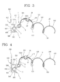
- Figures 3 to 7 show a first embodiment of a connecting device 1, according to the present invention, for making the connection between the chassis of the coaches of the articulated vehicle and the gangway bellows cover 100.
- the connecting device 1 comprises a connecting element 2 having a grip portion 3 which can be stably connected to the end edge 102a of the inner gangway bellows cover 102, and an engagement portion 4 fixed to the grip portion 3 and which may be inserted in the groove 400.
- the connecting element 2 has a main direction of extension parallel with the main direction of extension of the groove 400.
- the engagement portion 4 is wedge-shaped (and, more precisely, it is mushroom-shaped) to facilitate its insertion in the groove 400, and it has a first portion and a second portion, respectively labelled 4a and 4b, opposite each other and designed to make contact with the front walls 310, 320 of the duct 300.
- Each of the two portions 4a, 4b has a recess 5 designed to stably hook to one of the front walls 310, 320 of the duct 300 to form a permanent connection, by means of undercuts, of the engagement portion 4 in the groove 400.
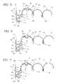
- the engagement portion 4 can deform between a first position illustrated in Figures 4 and 5 , in which the two portions 4a, 4b are close to each other to allow insertion in the front opening 500, and a second position, illustrated in Figures 6 and 7 in which the two portions 4a, 4b are distant from each other to stably engage with the respective front walls 310, 320 of the duct 300.
- the engagement portion 4 is preferably made of metal and more preferably of aluminium. Moreover, the entire connecting element 2 is preferably made using a metal section, in particular made of aluminium.
- the engagement portion 4 is elastically deformable between the above-mentioned two positions, thus allowing a snap-on connection with the front walls 310, 320 of the duct 300, which form projections acting as retaining elements for stably holding the engagement portion 4 in the groove 400.
- the engagement portion 4 can easily be inserted by pushing into the front opening 500 of the duct 300 and during said step the engagement portion elastically deforms until it locks snap-on - style (thanks to its elastic return) on the front walls 310, 320 once it has been completely inserted ( Figure 6 ).
- the two portions 4a, 4b of the engagement portion 4 form respective guide surfaces "S" designed to make contact with the front walls 310, 320 and to slide relative to the latter, promoting insertion of the engagement portion 4 in the front opening 500 of the duct 300.
- the guide surfaces "S” converge towards a front portion of the engagement portion 4 in such a way that the gradual insertion of the engagement portion 4 in the front opening 500 causes the two portions 4a, 4b of the engagement portion 4 to gradually move towards each other.
- the engagement portion 4 is preferably obtained using a thin section which follows the outer profile of the engagement portion 4, which therefore remains hollow, forming the cavity 7 between the two portions 4a, 4b.
- the thin section has a thickness adapt to confer an elastic deformability to the engagement portion and, in particular, to allow a mutual approaching and spreading movement between the two portions 4a, 4b of the engaging portion 4.
- the connecting device 1 comprises fixing means acting on the two portions 4a, 4b of the engagement portion 4 to stably hold them distant from each other, in particular when the engagement portion 4 is inserted in the groove 400.
- the fixing means preferably comprise a removable insert, which can be inserted in the cavity 7 by forcing it with pressure or by screwing between the two portions 4a, 4b for keeping the two portions 4a, 4b pushed away one from the other and therefore wedged within the groove 400. The removal of the insert allows a re-approaching of the portions 4a, 4b and therefore the extraction of the engagement portion 4 from the groove 400.
- the fixing means comprise an elastic seal 6 which can be inserted by pressing it into a cavity 7 made in the engagement portion 4 between the above-mentioned two portions 4a, 4b.
- the cavity 7, whose main direction of extension is parallel with the main direction of extension of the groove 400 and of the engagement portion 4, is designed to lie along the front opening 500 when the engagement portion 4 is inserted in the groove 400 ( Figures 6 and 7 ).
- the two portions 4a, 4b of the engagement portion 4 have a plurality of inner protuberances or threads 8 which can engage by making contact with the seal 6 and which are designed to improve adherence between the engagement portion 4 and the seal 6.
- the seal 6 is also wedge-shaped, for stable insertion in the cavity 7.
- the seal 6 also has at least one inner hollow 9 designed to promote seal 6 deformation by crushing during its insertion in the cavity 7.
- Figure 8 shows an alternative embodiment in which the fixing means comprise a plurality of spacer elements 10 (only one of which is visible in Figure 8 ) inserted using pressure in the cavity 7 at a predetermined distance from each other.
- each spacer element 10 has a through-hole for the insertion of a threaded element 10a which completely passes through the spacer element and also passes through a through-hole made in the front portion of the engagement portion until it screws into a hole made in the rear wall 330 of the duct 300.
- the threaded element 10a therefore permanently locks the spacer element 10, and therefore the engagement portion 4, relative to the duct 300.
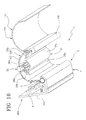
- Figures 10 to 12 show an alternative embodiment of the connecting device 1 in which the engagement portion 4 comprises a first block 11a made of a first material, and a second block 11b fixed to the first block 11a and made of a second material.
- the two materials preferably have different deformability properties.
- Each of the two blocks 11a, 11b has a respective portion 11c, 11d forming the recess 5.
- the engagement portion 4 is elastically deformable between a first position ( Figure 10 ), in which the portion 11c of one block 11a is close to the other block 11b to promote insertion of the engagement portion 4 in the groove 400 ( Figure 11 ), and a second position ( Figure 12 ), in which the portion 11c of the block 11a is distant from the other block 11b, allowing the portion 11c to hook inside the groove 400, forming a stable connection of the engagement portion 4 in the groove 400.
- only one of the two blocks 11a is deformable to the extent that it allows deformation of the respective portion 11c.
- the other block 11b is substantially non-deformable.
- both blocks are deformable to the extent that they allow deformation of the respective portion 11c, 11d.
- Figures 13 to 15 show another alternative embodiment of the connecting device 1, in which the engagement portion 4 comprises a rigid element, that is to say, an element which is substantially non-deformable, preferably a section 17, which can be inserted in the groove 400 and which has a first engagement surface 18 that can be abutted to an inner surface 410 of the groove 400, and at least a second engagement surface 19 which can be abutted to an outer surface 420 of the duct 300.
- the engagement portion 4 comprises a rigid element, that is to say, an element which is substantially non-deformable, preferably a section 17, which can be inserted in the groove 400 and which has a first engagement surface 18 that can be abutted to an inner surface 410 of the groove 400, and at least a second engagement surface 19 which can be abutted to an outer surface 420 of the duct 300.
- the two engagement surfaces 18, 19 are shaped to match the corresponding inner and outer surfaces 410, 420 to which they are abutted, and are preferably flat.
- the inner surface 410 of the groove 400 is formed by one of the front walls 310, 320 of the duct 300.
- the outer surface 420 of the groove 400 is formed by one of the lateral walls 340 of the duct 300, and in particular by the lateral wall 340 opposite the wall 310 which forms the inner surface 410. In that way, the two surfaces, one inner 410 and one outer 420, are perpendicular to each other and give the section 17 an "L" shape.
- the section 17 in turn has a first portion 17a and a second portion 17b at a right angle to each other.
- the first portion 17a forms the first engagement surface 18 and the second portion 17b forms the second engagement surface 19.
- the first portion 17a of the section 17 has a first, outermost stretch 20, which can be abutted inside the groove 400 and which comprises the first engagement surface 18, and a second stretch 21, between the first stretch 20 and the second portion 17b of the section 17, which can be abutted outside the groove 400 (and therefore outside the duct 300).
- the two stretches 20, 21 each rest on a different front wall 310, 320 of the duct 300 by means of respective flat walls which lie in parallel offset planes.
- the two stretches 20, 21 are connected by means of an angled connector 22.
- the first portion 17a also has a protrusion 23 extending away from the second stretch 21 and delimiting, in conjunction with the second stretch 21 and with the second portion 17b of the section 17, a housing 24 for the front wall 310 of the duct 300.
- the section 17 may be inserted with a first movement setting it at an angle relative to the duct 300 ( Figure 13 ), then a translation of the section 17 with insertion of the first portion 17a in the groove 400 through the front opening 500 ( Figure 14 ) and a subsequent straightening of the section 17 with insertion of the front wall 310 in the housing 24 and contact between the second engagement surface 19 and the lateral wall 340.
- the section 17 is fixed to the duct 300 using one or more locking screws 25, preferably applied between the second portion 17b of the section 17 and the lateral wall 340 of the duct 300 on which it is applied.
- the connecting device 1 also comprises joining means 26, applied to the inner gangway bellows cover 102 at least at one of the bands 110, preferably the band 110 closest to the vehicle chassis (that is to say, the band 110 closest to the join with the vehicle).
- the joining means 26 are preferably located in a central portion of the band 110, that is to say, in a middle section of the band 110.
- a covering element 27 is preferably applied, to cover the joining means 26 and hide the joining means 26 from view.
- the covering element comprises a strip of rigid or deformable material, having opposite outer flaps 27a, 27b which can be stably applied to portions of the gangway bellows cover 102 located on opposite sides of the joining means 26.
- the covering element 27 is preferably applied to the concave side of the band 110.
- the covering element 27 preferably has a central portion 27c, between the flaps 27a, 27b, which is raised relative to the flaps so that it can be adapted to the dimensions of the joining means 26 that it covers.
- the inner gangway bellows cover 102 is divided into two parts 104, 105 and the joining means 26 are positioned at the joining line between the two parts 104, 105 of the inner gangway bellows cover 102 to create a reversible stable connection between the two portions 104, 105.
- the part 104 between the connecting element 2 and the joining means 26 remains stably connected to the vehicle chassis even when the joining means 26 are released to allow removal of the other part 105 of the gangway bellows cover 102 and subsequent simple and practical refitting. Therefore, the part 104 of the gangway bellows cover 102 is preferably kept to a minimum so as to maximise the portion 105 of gangway bellows cover which can be removed, for example for vehicle cleaning, maintenance and inspection.
- the joining means 26 comprise a zip fastener.
- the zip fastener has a first flap 28 stably connected to an end flap of the first part 104 of the gangway bellows cover 102 and a second flap 29 stably connected to an end flap of the second part 105 of the gangway bellows cover 102.
- the covering element 27 is removably applied to the gangway bellows cover 102 at least at one of its flaps 27a, 27b, and preferably at both.
- Said removable connection is for example achieved using snap-on couplings, Velcro® or other removable connecting means.
- the joining means 26 can be applied to the inner gangway bellows cover 102 (and if necessary also to the outer gangway bellows cover 101) in all of the embodiments of the connecting device 1 described and illustrated.
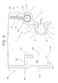
- the grip portion 3 is connected to the engagement portion 4 by means of a hinge for pivoting about a hinge axis "X" with respect to the engagement portion 4.
- the hinge allows the grip portion 3 to rotate freely with respect to the engagement portion 4 in such a way to compensate any misalignment of the gangway bellows cover during motion of the vehicle.
- the engagement portion 4 has a receiving portion 12 forming a cylindrical cavity 13 with circular cross-section extending about the axis "X", whilst the grip portion 3 has a cylindrical element 14 rotatably inserted in the cylindrical cavity 13 so that it can rotate about the hinge axis "X".
- the hinge axis "X" is preferably parallel with the main direction of extension of the connecting element 2.
- the connecting element 2 has a receiving portion 12 fixed to the engaging portion 4 and connected to the grip portion 3 in a pivotable manner about the hinge axis "X". More in detail, the receiving portion 12 is fixed to one of the two portions 4a, 4b of the engagement portion 4, the other portion 4b defining an end portion of the engagement portion 4.
- the receiving portion 12 extends away from the portion 4a of the engagement portion 4, preferably in a direction parallel to the direction of mutual approaching and spreading movement between the two portions 4a, 4b of the engaging portion 4 for allowing a free and easy access to the cavity 7 for inserting the fixing means.
- the grip portion 3 also comprises a supporting element 15 rigidly connected to the cylindrical element 14 so that it can rotate with the latter about the axis "X".
- the supporting element 15 has a pair of parallel plates 16 between them forming a housing for the end edge 102a of the inner gangway bellows cover 102.
- the end edge 102a of the inner gangway bellows cover 102 is held in the housing by gluing, or by means of fixing screws or other anchoring systems.
- the receiving portion 12 has two opposite retaining portions 12a, 12b which are distant from each other to allow the passage of the parallel plates 16 and also to allow the supporting element 15 to rotate through a predetermined angle.
- the two retaining portions 12a, 12b of the receiving portion 12 form a supporting surface for supporting the supporting element 15 and the cylindrical element 14, having a gap zone where the two parallel plates 16 of the supporting element 15 are positioned.
- the grip portion 3 described is used in all of the embodiments in accordance with the present invention.
- the present invention achieves the preset aims, overcoming the disadvantages of the prior art.
- the shape of the connecting element allows two stable anchoring points to be made available (provided by the two portions of the engagement portion) which can be further stabilised using the fixing means. Also, where the engagement portion is made of metal, there is a very stable connection which resists wear and fatigue.
- the engagement portion is made using two blocks made of different materials, there is a significant simplification of assembly of the engagement portion, which can be applied in a single insertion step in the groove without having to prepare additional fixing elements.
- the hinged structure of the connecting element allows the end edge of the inner gangway bellows cover to rotate relative to the vehicle chassis. This allows significant absorption of the bending movements to which the gangway bellows cover is subjected while the vehicle is moving, consequently reducing the bending stresses at the portion of the gangway bellows cover connected to the chassis. As a result, the gangway bellows cover lasts for longer without rips and/or tears which would otherwise require it to be substituted.
- zip fastener significantly simplifies maintenance, inspection or cleaning operations for the vehicle rotary platform and therefore the gangway between the vehicle coaches, since the connecting element no longer has to be removed from the duct. Instead, the zip fastener can simply be used, being applied on the gangway bellows cover in a position which allows the removal of almost all of the gangway bellows cover.
Landscapes
- Engineering & Computer Science (AREA)
- Mechanical Engineering (AREA)
- Life Sciences & Earth Sciences (AREA)
- Wood Science & Technology (AREA)
- Diaphragms And Bellows (AREA)
- Joints Allowing Movement (AREA)
- Automobile Manufacture Line, Endless Track Vehicle, Trailer (AREA)
- Sealing Devices (AREA)
Priority Applications (1)
| Application Number | Priority Date | Filing Date | Title |
|---|---|---|---|
| PL09165684T PL2149462T3 (pl) | 2008-07-31 | 2009-07-16 | Urządzenie do łączenia osłony harmonii międzywagonowej i podwozia pojazdów przegubowych |
Applications Claiming Priority (1)
| Application Number | Priority Date | Filing Date | Title |
|---|---|---|---|
| ITBO2008A000489A IT1390798B1 (it) | 2008-07-31 | 2008-07-31 | Dispositivo di collegamento tra il soffietto ed il telaio di veicoli articolati. |
Publications (2)
| Publication Number | Publication Date |
|---|---|
| EP2149462A1 true EP2149462A1 (fr) | 2010-02-03 |
| EP2149462B1 EP2149462B1 (fr) | 2012-09-12 |
Family
ID=40445574
Family Applications (1)
| Application Number | Title | Priority Date | Filing Date |
|---|---|---|---|
| EP09165684A Active EP2149462B1 (fr) | 2008-07-31 | 2009-07-16 | Dispositif pour la connexion d'une enveloppe de soufflet et du châssis de véhicules articulés |
Country Status (4)
| Country | Link |
|---|---|
| US (1) | US8485108B2 (fr) |
| EP (1) | EP2149462B1 (fr) |
| IT (1) | IT1390798B1 (fr) |
| PL (1) | PL2149462T3 (fr) |
Cited By (8)
| Publication number | Priority date | Publication date | Assignee | Title |
|---|---|---|---|---|
| EP2562014A1 (fr) * | 2011-08-24 | 2013-02-27 | Hübner GmbH | Soufflet d'un passage entre deux véhicules reliés de manière articulée d'un véhicule articulé |
| EP2604451A1 (fr) * | 2011-12-16 | 2013-06-19 | Hübner GmbH | Soufflet à plis ou soufflet d'un passage entre deux véhicules liés de manière articulée |
| EP2636547A1 (fr) * | 2012-03-06 | 2013-09-11 | Hübner GmbH | Soufflet d'un passage entre deux véhicules articulés |
| WO2014004632A1 (fr) * | 2012-06-26 | 2014-01-03 | A & A Manufacturing Co.,Inc. | Soufflet plié |
| EP2740618A1 (fr) * | 2012-12-05 | 2014-06-11 | Hübner GmbH & Co. KG | Véhicule comprenant au moins deux pièces de véhicule reliées de manière articulée |
| EP2987664A1 (fr) * | 2014-08-21 | 2016-02-24 | Hübner GmbH & Co. KG | passage entre véhicules articulés |
| EP3100929A1 (fr) * | 2015-06-02 | 2016-12-07 | ULTIMATE Europe Transportation Equipment GmbH | Revetement de paroi laterale |
| AT18193U1 (de) * | 2022-10-14 | 2024-04-15 | Plasser & Theurer Export Von Bahnbaumaschinen Gmbh | Dichteinrichtung zum dichten Verbinden eines ersten Körpers mit einem zweiten Körper, insbesondere für eine Gleisbauvorrichtung, und Vorrichtung |
Families Citing this family (9)
| Publication number | Priority date | Publication date | Assignee | Title |
|---|---|---|---|---|
| PT2106984E (pt) * | 2008-03-31 | 2010-09-30 | Atg Autotechnik Gmbh | Fole |
| US8733777B2 (en) | 2010-02-05 | 2014-05-27 | HÜBNER GmbH & Co. KG | Corrugation bellows of a transfer between two pivotably interconnected vehicles |
| PL2353894T3 (pl) * | 2010-02-05 | 2015-10-30 | Huebner Gmbh & Co Kg | Osłona harmonijkowa falista do przejścia między dwoma połączonymi przegubowo pojazdami |
| DE102011082190B4 (de) * | 2011-09-06 | 2015-11-19 | Siemens Aktiengesellschaft | Magnetresonanzeinrichtung mit Empfangsspulen und Verfahren zum Betrieb einer Magnetresonanzeinrichtung |
| US9512612B2 (en) * | 2014-12-05 | 2016-12-06 | Ted Gower | Retainer inserts for barriers |
| ES2805061T3 (es) * | 2015-04-02 | 2021-02-10 | Huebner Gmbh & Co Kg | Fuelle, p. ej. de un paso entre dos vehículos unidos el uno con el otro de forma articulada |
| PL3118081T3 (pl) * | 2015-07-15 | 2020-02-28 | HÜBNER GmbH & Co. KG | Pojazd, wyposażony w przynajmniej dwa człony, połączone ze sobą przegubowo |
| EP3738798B1 (fr) * | 2019-05-14 | 2021-04-07 | Dellner Couplers AB | Cadre d'extrémité d'une passerelle, passerelle, véhicule à plusieurs cabines et procédé de connexion de la passerelle à un véhicule à plusieurs cabines |
| EP3738799B1 (fr) | 2019-05-14 | 2023-06-28 | Dellner Couplers AB | Passerelle pour un véhicule à plusieurs cabines et procédé de fixation d'un soufflet d'une passerelle à un cadre d'extrémité d'une passerelle |
Citations (9)
| Publication number | Priority date | Publication date | Assignee | Title |
|---|---|---|---|---|
| US1450007A (en) * | 1921-10-27 | 1923-03-27 | Charles W Pflager | Car diaphragm |
| US2287667A (en) * | 1940-12-07 | 1942-06-23 | Winfield B Brown | Awning fastener |
| FR1058014A (fr) * | 1952-04-22 | 1954-03-12 | Maschf Augsburg Nuernberg Ag | Dispositif de protection pour passerelles de communication entre des véhicules circulant sur rails, en particulier des voitures motrices |
| US5259323A (en) * | 1991-02-21 | 1993-11-09 | Hubner-Gummi - Und Kunststoff | Mounting arrangement and method for gangway bellows for gangways of articulated vehicles |
| EP0631890A1 (fr) * | 1993-07-02 | 1995-01-04 | HÜBNER Gummi- und Kunststoff GmbH | Dispositif de protection pour passage de communication en particulier pour véhicules routiers articulés |
| US5884565A (en) * | 1995-06-03 | 1999-03-23 | Hubner Gummi- Und Kunstsoff Gmbh | Device for covering the track joint between the rotary plate of a swivel joint and the expansion or concertina bellows of an articulated vehicle |
| EP1162121A1 (fr) * | 2000-06-05 | 2001-12-12 | Le Joint Francais Snc | Dispositif de fixation d'un soufflet et procédé pour sa mise en oeuvre |
| FR2858287A1 (fr) * | 2003-07-30 | 2005-02-04 | Hutchinson | Perfectionnement a un dispositif de fixation d'un soufflet d'intercommunication, en particulier pour materiel de transport |
| DE102005032218A1 (de) * | 2005-07-09 | 2007-01-11 | Hübner GmbH | Vorrichtung zum Abdecken der Spurfuge (Spurfugenabdeckung) zwischen dem Drehteller und dem Balg eines Übergangs zwischen zwei gelenkig miteinander verbundener Fahrzeugteile |
Family Cites Families (8)
| Publication number | Priority date | Publication date | Assignee | Title |
|---|---|---|---|---|
| US1095909A (en) * | 1912-04-17 | 1914-05-05 | Curtain Supply Co | Car-vestibule diaphragm. |
| US1078758A (en) * | 1913-05-12 | 1913-11-18 | Curtain Supply Co | Car-diaphragm. |
| US2408473A (en) * | 1945-06-21 | 1946-10-01 | Clarence P Nelson | Dust seal for adjoining railroad cars |
| US2893782A (en) * | 1955-12-01 | 1959-07-07 | Gen Motors Corp | Attachment of convertible top fabric to side rail |
| FR2751291B1 (fr) * | 1996-07-17 | 1998-10-02 | Joint Francais | Soufflet d'intercirculation pour materiel roulant |
| DE102006002655B4 (de) * | 2006-01-19 | 2008-03-06 | Hübner GmbH | Balg eines Übergangs zwischen zwei gelenkig miteinander verbundenen Fahrzeugen |
| IT1390797B1 (it) * | 2008-07-31 | 2011-10-19 | Pei Protezioni Elaborazioni | Dispositivo di collegamento tra il soffietto ed il telaio di veicoli articolati. |
| IT1390795B1 (it) * | 2008-07-31 | 2011-10-19 | Pei Protezioni Elaborazioni | Dispositivo di collegamento a soffietto per veicoli articolati. |
-
2008
- 2008-07-31 IT ITBO2008A000489A patent/IT1390798B1/it active
-
2009
- 2009-07-16 PL PL09165684T patent/PL2149462T3/pl unknown
- 2009-07-16 EP EP09165684A patent/EP2149462B1/fr active Active
- 2009-07-28 US US12/510,673 patent/US8485108B2/en active Active
Patent Citations (9)
| Publication number | Priority date | Publication date | Assignee | Title |
|---|---|---|---|---|
| US1450007A (en) * | 1921-10-27 | 1923-03-27 | Charles W Pflager | Car diaphragm |
| US2287667A (en) * | 1940-12-07 | 1942-06-23 | Winfield B Brown | Awning fastener |
| FR1058014A (fr) * | 1952-04-22 | 1954-03-12 | Maschf Augsburg Nuernberg Ag | Dispositif de protection pour passerelles de communication entre des véhicules circulant sur rails, en particulier des voitures motrices |
| US5259323A (en) * | 1991-02-21 | 1993-11-09 | Hubner-Gummi - Und Kunststoff | Mounting arrangement and method for gangway bellows for gangways of articulated vehicles |
| EP0631890A1 (fr) * | 1993-07-02 | 1995-01-04 | HÜBNER Gummi- und Kunststoff GmbH | Dispositif de protection pour passage de communication en particulier pour véhicules routiers articulés |
| US5884565A (en) * | 1995-06-03 | 1999-03-23 | Hubner Gummi- Und Kunstsoff Gmbh | Device for covering the track joint between the rotary plate of a swivel joint and the expansion or concertina bellows of an articulated vehicle |
| EP1162121A1 (fr) * | 2000-06-05 | 2001-12-12 | Le Joint Francais Snc | Dispositif de fixation d'un soufflet et procédé pour sa mise en oeuvre |
| FR2858287A1 (fr) * | 2003-07-30 | 2005-02-04 | Hutchinson | Perfectionnement a un dispositif de fixation d'un soufflet d'intercommunication, en particulier pour materiel de transport |
| DE102005032218A1 (de) * | 2005-07-09 | 2007-01-11 | Hübner GmbH | Vorrichtung zum Abdecken der Spurfuge (Spurfugenabdeckung) zwischen dem Drehteller und dem Balg eines Übergangs zwischen zwei gelenkig miteinander verbundener Fahrzeugteile |
Cited By (13)
| Publication number | Priority date | Publication date | Assignee | Title |
|---|---|---|---|---|
| CN102950983B (zh) * | 2011-08-24 | 2015-05-27 | 许布奈有限公司 | 铰接式车辆的两个彼此铰接的车辆之间的过渡部的折棚 |
| CN102950983A (zh) * | 2011-08-24 | 2013-03-06 | 许布奈有限公司 | 铰接式车辆的两个彼此铰接的车辆之间的过渡部的折棚 |
| US8556285B2 (en) | 2011-08-24 | 2013-10-15 | Hübner GmbH | Bellows of a transition between two vehicles of an articulated vehicle articulately connected to each other |
| EP2562014A1 (fr) * | 2011-08-24 | 2013-02-27 | Hübner GmbH | Soufflet d'un passage entre deux véhicules reliés de manière articulée d'un véhicule articulé |
| RU2527588C2 (ru) * | 2011-08-24 | 2014-09-10 | ХЮБНЕР ГмбХ | Сильфонное уплотнение перехода между двумя соединенными друг с другом шарнирами сочленённого транспортного средства |
| EP2604451A1 (fr) * | 2011-12-16 | 2013-06-19 | Hübner GmbH | Soufflet à plis ou soufflet d'un passage entre deux véhicules liés de manière articulée |
| EP2636547A1 (fr) * | 2012-03-06 | 2013-09-11 | Hübner GmbH | Soufflet d'un passage entre deux véhicules articulés |
| WO2014004632A1 (fr) * | 2012-06-26 | 2014-01-03 | A & A Manufacturing Co.,Inc. | Soufflet plié |
| EP2740618A1 (fr) * | 2012-12-05 | 2014-06-11 | Hübner GmbH & Co. KG | Véhicule comprenant au moins deux pièces de véhicule reliées de manière articulée |
| EP2987664A1 (fr) * | 2014-08-21 | 2016-02-24 | Hübner GmbH & Co. KG | passage entre véhicules articulés |
| EP3100929A1 (fr) * | 2015-06-02 | 2016-12-07 | ULTIMATE Europe Transportation Equipment GmbH | Revetement de paroi laterale |
| AT18193U1 (de) * | 2022-10-14 | 2024-04-15 | Plasser & Theurer Export Von Bahnbaumaschinen Gmbh | Dichteinrichtung zum dichten Verbinden eines ersten Körpers mit einem zweiten Körper, insbesondere für eine Gleisbauvorrichtung, und Vorrichtung |
| EP4353505A1 (fr) * | 2022-10-14 | 2024-04-17 | Plasser & Theurer, Export von Bahnbaumaschinen, Gesellschaft m.b.H. | Dispositif d'étanchéité pour relier de manière étanche un premier corps à un deuxième corps, en particulier pour un dispositif de pose de voie |
Also Published As
| Publication number | Publication date |
|---|---|
| ITBO20080489A1 (it) | 2010-02-01 |
| IT1390798B1 (it) | 2011-10-19 |
| US8485108B2 (en) | 2013-07-16 |
| US20100025961A1 (en) | 2010-02-04 |
| PL2149462T3 (pl) | 2013-02-28 |
| EP2149462B1 (fr) | 2012-09-12 |
Similar Documents
| Publication | Publication Date | Title |
|---|---|---|
| EP2149462B1 (fr) | Dispositif pour la connexion d'une enveloppe de soufflet et du châssis de véhicules articulés | |
| US8297197B2 (en) | Device for connecting the gangway bellows cover and the chassis of articulated vehicles | |
| US20190092285A1 (en) | Locking device between a wiper blade and a wiper blade assembly holder | |
| US5259323A (en) | Mounting arrangement and method for gangway bellows for gangways of articulated vehicles | |
| KR20050033046A (ko) | 안전 체결구를 포함하는 자동차 윈드스크린용 와이퍼 | |
| KR20130108578A (ko) | 블레이드를 와이퍼에 고정시키는 방법 | |
| US9476480B2 (en) | Energy guiding chain | |
| US20160107616A1 (en) | Windscreen wiper device | |
| MX2014001075A (es) | Adaptador de limpiaparabrisas con posicion de seguridad. | |
| CN103171412A (zh) | 汽车门的密封装置 | |
| EP2817184B1 (fr) | Balai d'essuie-glaces | |
| US10676068B2 (en) | Cap and driving arm for a wiping device for a motor vehicle | |
| US20080250596A1 (en) | Wiper Blade | |
| US9744947B2 (en) | Connector between a wiper blade and a drive arm | |
| EP2006174A2 (fr) | Système d'assemblage de composants de lame | |
| US20130318735A1 (en) | Windscreen wiper device | |
| EP3481682B1 (fr) | Dispositif de type essuie-glace | |
| US20170197590A1 (en) | Casing for a windscreen wiper drive rod | |
| US7866683B2 (en) | Gangway bellows | |
| US20160304062A1 (en) | End-piece intended to be mounted on a flexible support and wiper including the end-piece and the flexible support | |
| US20090007511A1 (en) | Window Unit Having Decorative Strip Mounted Thereon | |
| CN106043238B (zh) | 用于擦拭器的端部盖 | |
| US20230311815A1 (en) | Rear beam arm and blade assembly | |
| AU2005202827A1 (en) | Weather strip and mounting structure and manufacturing method thereof | |
| EP3409538B1 (fr) | Garde-corps de toit de voiture et système d'étanchéité |
Legal Events
| Date | Code | Title | Description |
|---|---|---|---|
| PUAI | Public reference made under article 153(3) epc to a published international application that has entered the european phase |
Free format text: ORIGINAL CODE: 0009012 |
|
| AK | Designated contracting states |
Kind code of ref document: A1 Designated state(s): AT BE BG CH CY CZ DE DK EE ES FI FR GB GR HR HU IE IS IT LI LT LU LV MC MK MT NL NO PL PT RO SE SI SK SM TR |
|
| AX | Request for extension of the european patent |
Extension state: AL BA RS |
|
| 17P | Request for examination filed |
Effective date: 20100603 |
|
| 17Q | First examination report despatched |
Effective date: 20101028 |
|
| GRAP | Despatch of communication of intention to grant a patent |
Free format text: ORIGINAL CODE: EPIDOSNIGR1 |
|
| GRAS | Grant fee paid |
Free format text: ORIGINAL CODE: EPIDOSNIGR3 |
|
| GRAA | (expected) grant |
Free format text: ORIGINAL CODE: 0009210 |
|
| AK | Designated contracting states |
Kind code of ref document: B1 Designated state(s): AT BE BG CH CY CZ DE DK EE ES FI FR GB GR HR HU IE IS IT LI LT LU LV MC MK MT NL NO PL PT RO SE SI SK SM TR |
|
| REG | Reference to a national code |
Ref country code: GB Ref legal event code: FG4D |
|
| REG | Reference to a national code |
Ref country code: CH Ref legal event code: EP |
|
| REG | Reference to a national code |
Ref country code: AT Ref legal event code: REF Ref document number: 574877 Country of ref document: AT Kind code of ref document: T Effective date: 20120915 |
|
| REG | Reference to a national code |
Ref country code: IE Ref legal event code: FG4D |
|
| REG | Reference to a national code |
Ref country code: DE Ref legal event code: R096 Ref document number: 602009009650 Country of ref document: DE Effective date: 20121108 |
|
| PG25 | Lapsed in a contracting state [announced via postgrant information from national office to epo] |
Ref country code: LT Free format text: LAPSE BECAUSE OF FAILURE TO SUBMIT A TRANSLATION OF THE DESCRIPTION OR TO PAY THE FEE WITHIN THE PRESCRIBED TIME-LIMIT Effective date: 20120912 Ref country code: NO Free format text: LAPSE BECAUSE OF FAILURE TO SUBMIT A TRANSLATION OF THE DESCRIPTION OR TO PAY THE FEE WITHIN THE PRESCRIBED TIME-LIMIT Effective date: 20121212 Ref country code: CY Free format text: LAPSE BECAUSE OF FAILURE TO SUBMIT A TRANSLATION OF THE DESCRIPTION OR TO PAY THE FEE WITHIN THE PRESCRIBED TIME-LIMIT Effective date: 20120912 Ref country code: FI Free format text: LAPSE BECAUSE OF FAILURE TO SUBMIT A TRANSLATION OF THE DESCRIPTION OR TO PAY THE FEE WITHIN THE PRESCRIBED TIME-LIMIT Effective date: 20120912 Ref country code: HR Free format text: LAPSE BECAUSE OF FAILURE TO SUBMIT A TRANSLATION OF THE DESCRIPTION OR TO PAY THE FEE WITHIN THE PRESCRIBED TIME-LIMIT Effective date: 20120912 |
|
| REG | Reference to a national code |
Ref country code: NL Ref legal event code: VDEP Effective date: 20120912 |
|
| REG | Reference to a national code |
Ref country code: AT Ref legal event code: MK05 Ref document number: 574877 Country of ref document: AT Kind code of ref document: T Effective date: 20120912 |
|
| REG | Reference to a national code |
Ref country code: LT Ref legal event code: MG4D Effective date: 20120912 |
|
| PG25 | Lapsed in a contracting state [announced via postgrant information from national office to epo] |
Ref country code: SI Free format text: LAPSE BECAUSE OF FAILURE TO SUBMIT A TRANSLATION OF THE DESCRIPTION OR TO PAY THE FEE WITHIN THE PRESCRIBED TIME-LIMIT Effective date: 20120912 Ref country code: SE Free format text: LAPSE BECAUSE OF FAILURE TO SUBMIT A TRANSLATION OF THE DESCRIPTION OR TO PAY THE FEE WITHIN THE PRESCRIBED TIME-LIMIT Effective date: 20120912 Ref country code: GR Free format text: LAPSE BECAUSE OF FAILURE TO SUBMIT A TRANSLATION OF THE DESCRIPTION OR TO PAY THE FEE WITHIN THE PRESCRIBED TIME-LIMIT Effective date: 20121213 Ref country code: LV Free format text: LAPSE BECAUSE OF FAILURE TO SUBMIT A TRANSLATION OF THE DESCRIPTION OR TO PAY THE FEE WITHIN THE PRESCRIBED TIME-LIMIT Effective date: 20120912 |
|
| REG | Reference to a national code |
Ref country code: PL Ref legal event code: T3 |
|
| PG25 | Lapsed in a contracting state [announced via postgrant information from national office to epo] |
Ref country code: ES Free format text: LAPSE BECAUSE OF FAILURE TO SUBMIT A TRANSLATION OF THE DESCRIPTION OR TO PAY THE FEE WITHIN THE PRESCRIBED TIME-LIMIT Effective date: 20121223 Ref country code: IS Free format text: LAPSE BECAUSE OF FAILURE TO SUBMIT A TRANSLATION OF THE DESCRIPTION OR TO PAY THE FEE WITHIN THE PRESCRIBED TIME-LIMIT Effective date: 20130112 Ref country code: RO Free format text: LAPSE BECAUSE OF FAILURE TO SUBMIT A TRANSLATION OF THE DESCRIPTION OR TO PAY THE FEE WITHIN THE PRESCRIBED TIME-LIMIT Effective date: 20120912 Ref country code: NL Free format text: LAPSE BECAUSE OF FAILURE TO SUBMIT A TRANSLATION OF THE DESCRIPTION OR TO PAY THE FEE WITHIN THE PRESCRIBED TIME-LIMIT Effective date: 20120912 Ref country code: BE Free format text: LAPSE BECAUSE OF FAILURE TO SUBMIT A TRANSLATION OF THE DESCRIPTION OR TO PAY THE FEE WITHIN THE PRESCRIBED TIME-LIMIT Effective date: 20120912 Ref country code: EE Free format text: LAPSE BECAUSE OF FAILURE TO SUBMIT A TRANSLATION OF THE DESCRIPTION OR TO PAY THE FEE WITHIN THE PRESCRIBED TIME-LIMIT Effective date: 20120912 Ref country code: CZ Free format text: LAPSE BECAUSE OF FAILURE TO SUBMIT A TRANSLATION OF THE DESCRIPTION OR TO PAY THE FEE WITHIN THE PRESCRIBED TIME-LIMIT Effective date: 20120912 |
|
| PG25 | Lapsed in a contracting state [announced via postgrant information from national office to epo] |
Ref country code: PT Free format text: LAPSE BECAUSE OF FAILURE TO SUBMIT A TRANSLATION OF THE DESCRIPTION OR TO PAY THE FEE WITHIN THE PRESCRIBED TIME-LIMIT Effective date: 20130114 Ref country code: SK Free format text: LAPSE BECAUSE OF FAILURE TO SUBMIT A TRANSLATION OF THE DESCRIPTION OR TO PAY THE FEE WITHIN THE PRESCRIBED TIME-LIMIT Effective date: 20120912 |
|
| PG25 | Lapsed in a contracting state [announced via postgrant information from national office to epo] |
Ref country code: AT Free format text: LAPSE BECAUSE OF FAILURE TO SUBMIT A TRANSLATION OF THE DESCRIPTION OR TO PAY THE FEE WITHIN THE PRESCRIBED TIME-LIMIT Effective date: 20120912 |
|
| PLBE | No opposition filed within time limit |
Free format text: ORIGINAL CODE: 0009261 |
|
| STAA | Information on the status of an ep patent application or granted ep patent |
Free format text: STATUS: NO OPPOSITION FILED WITHIN TIME LIMIT |
|
| PG25 | Lapsed in a contracting state [announced via postgrant information from national office to epo] |
Ref country code: DK Free format text: LAPSE BECAUSE OF FAILURE TO SUBMIT A TRANSLATION OF THE DESCRIPTION OR TO PAY THE FEE WITHIN THE PRESCRIBED TIME-LIMIT Effective date: 20120912 Ref country code: BG Free format text: LAPSE BECAUSE OF FAILURE TO SUBMIT A TRANSLATION OF THE DESCRIPTION OR TO PAY THE FEE WITHIN THE PRESCRIBED TIME-LIMIT Effective date: 20121212 |
|
| 26N | No opposition filed |
Effective date: 20130613 |
|
| REG | Reference to a national code |
Ref country code: DE Ref legal event code: R097 Ref document number: 602009009650 Country of ref document: DE Effective date: 20130613 |
|
| PG25 | Lapsed in a contracting state [announced via postgrant information from national office to epo] |
Ref country code: MC Free format text: LAPSE BECAUSE OF FAILURE TO SUBMIT A TRANSLATION OF THE DESCRIPTION OR TO PAY THE FEE WITHIN THE PRESCRIBED TIME-LIMIT Effective date: 20120912 |
|
| REG | Reference to a national code |
Ref country code: CH Ref legal event code: PL |
|
| GBPC | Gb: european patent ceased through non-payment of renewal fee |
Effective date: 20130716 |
|
| REG | Reference to a national code |
Ref country code: IE Ref legal event code: MM4A |
|
| PG25 | Lapsed in a contracting state [announced via postgrant information from national office to epo] |
Ref country code: GB Free format text: LAPSE BECAUSE OF NON-PAYMENT OF DUE FEES Effective date: 20130716 Ref country code: LI Free format text: LAPSE BECAUSE OF NON-PAYMENT OF DUE FEES Effective date: 20130731 Ref country code: CH Free format text: LAPSE BECAUSE OF NON-PAYMENT OF DUE FEES Effective date: 20130731 |
|
| PG25 | Lapsed in a contracting state [announced via postgrant information from national office to epo] |
Ref country code: IE Free format text: LAPSE BECAUSE OF NON-PAYMENT OF DUE FEES Effective date: 20130716 |
|
| PG25 | Lapsed in a contracting state [announced via postgrant information from national office to epo] |
Ref country code: SM Free format text: LAPSE BECAUSE OF FAILURE TO SUBMIT A TRANSLATION OF THE DESCRIPTION OR TO PAY THE FEE WITHIN THE PRESCRIBED TIME-LIMIT Effective date: 20120912 |
|
| PG25 | Lapsed in a contracting state [announced via postgrant information from national office to epo] |
Ref country code: MT Free format text: LAPSE BECAUSE OF FAILURE TO SUBMIT A TRANSLATION OF THE DESCRIPTION OR TO PAY THE FEE WITHIN THE PRESCRIBED TIME-LIMIT Effective date: 20120912 |
|
| PG25 | Lapsed in a contracting state [announced via postgrant information from national office to epo] |
Ref country code: LU Free format text: LAPSE BECAUSE OF NON-PAYMENT OF DUE FEES Effective date: 20130716 Ref country code: MK Free format text: LAPSE BECAUSE OF FAILURE TO SUBMIT A TRANSLATION OF THE DESCRIPTION OR TO PAY THE FEE WITHIN THE PRESCRIBED TIME-LIMIT Effective date: 20120912 Ref country code: HU Free format text: LAPSE BECAUSE OF FAILURE TO SUBMIT A TRANSLATION OF THE DESCRIPTION OR TO PAY THE FEE WITHIN THE PRESCRIBED TIME-LIMIT; INVALID AB INITIO Effective date: 20090716 |
|
| REG | Reference to a national code |
Ref country code: FR Ref legal event code: PLFP Year of fee payment: 8 |
|
| REG | Reference to a national code |
Ref country code: FR Ref legal event code: PLFP Year of fee payment: 9 |
|
| REG | Reference to a national code |
Ref country code: FR Ref legal event code: PLFP Year of fee payment: 10 |
|
| P01 | Opt-out of the competence of the unified patent court (upc) registered |
Effective date: 20230513 |
|
| PGFP | Annual fee paid to national office [announced via postgrant information from national office to epo] |
Ref country code: PL Payment date: 20250626 Year of fee payment: 17 |
|
| PGFP | Annual fee paid to national office [announced via postgrant information from national office to epo] |
Ref country code: DE Payment date: 20250728 Year of fee payment: 17 |
|
| PGFP | Annual fee paid to national office [announced via postgrant information from national office to epo] |
Ref country code: TR Payment date: 20250701 Year of fee payment: 17 Ref country code: IT Payment date: 20250728 Year of fee payment: 17 |
|
| PGFP | Annual fee paid to national office [announced via postgrant information from national office to epo] |
Ref country code: FR Payment date: 20250725 Year of fee payment: 17 |