EP2149596A1 - Odoranszugabevorrichtung und brennstoffgaszufuhrvorrichtung - Google Patents
Odoranszugabevorrichtung und brennstoffgaszufuhrvorrichtung Download PDFInfo
- Publication number
- EP2149596A1 EP2149596A1 EP08740199A EP08740199A EP2149596A1 EP 2149596 A1 EP2149596 A1 EP 2149596A1 EP 08740199 A EP08740199 A EP 08740199A EP 08740199 A EP08740199 A EP 08740199A EP 2149596 A1 EP2149596 A1 EP 2149596A1
- Authority
- EP
- European Patent Office
- Prior art keywords
- odorant
- addition
- gas
- environmental condition
- fuel gas
- Prior art date
- Legal status (The legal status is an assumption and is not a legal conclusion. Google has not performed a legal analysis and makes no representation as to the accuracy of the status listed.)
- Withdrawn
Links
Images


Classifications
-
- C—CHEMISTRY; METALLURGY
- C01—INORGANIC CHEMISTRY
- C01B—NON-METALLIC ELEMENTS; COMPOUNDS THEREOF; METALLOIDS OR COMPOUNDS THEREOF NOT COVERED BY SUBCLASS C01C
- C01B3/00—Hydrogen; Gaseous mixtures containing hydrogen; Separation of hydrogen from mixtures containing it; Purification of hydrogen; Reversible storage of hydrogen
- C01B3/0005—Reversible storage of hydrogen, e.g. by hydrogen getters or electrodes
- C01B3/001—Reversible storage of hydrogen, e.g. by hydrogen getters or electrodes characterised by the uptaking media; Treatment thereof
- C01B3/0018—Inorganic elements or compounds, e.g. oxides, nitrides, borohydrides or zeolites; Solutions thereof
- C01B3/0031—Intermetallic compounds; Metal alloys
-
- H—ELECTRICITY
- H01—ELECTRIC ELEMENTS
- H01M—PROCESSES OR MEANS, e.g. BATTERIES, FOR THE DIRECT CONVERSION OF CHEMICAL ENERGY INTO ELECTRICAL ENERGY
- H01M8/00—Fuel cells; Manufacture thereof
- H01M8/04—Auxiliary arrangements, e.g. for control of pressure or for circulation of fluids
-
- C—CHEMISTRY; METALLURGY
- C01—INORGANIC CHEMISTRY
- C01B—NON-METALLIC ELEMENTS; COMPOUNDS THEREOF; METALLOIDS OR COMPOUNDS THEREOF NOT COVERED BY SUBCLASS C01C
- C01B3/00—Hydrogen; Gaseous mixtures containing hydrogen; Separation of hydrogen from mixtures containing it; Purification of hydrogen; Reversible storage of hydrogen
- C01B3/0005—Reversible storage of hydrogen, e.g. by hydrogen getters or electrodes
-
- C—CHEMISTRY; METALLURGY
- C10—PETROLEUM, GAS OR COKE INDUSTRIES; TECHNICAL GASES CONTAINING CARBON MONOXIDE; FUELS; LUBRICANTS; PEAT
- C10L—FUELS NOT OTHERWISE PROVIDED FOR; NATURAL GAS; SYNTHETIC NATURAL GAS OBTAINED BY PROCESSES NOT COVERED BY SUBCLASSES C10G OR C10K; LIQUIFIED PETROLEUM GAS; USE OF ADDITIVES TO FUELS OR FIRES; FIRE-LIGHTERS
- C10L3/00—Gaseous fuels; Natural gas; Synthetic natural gas obtained by processes not covered by subclass C10G, C10K; Liquefied petroleum gas
- C10L3/003—Additives for gaseous fuels
- C10L3/006—Additives for gaseous fuels detectable by the senses
-
- G—PHYSICS
- G01—MEASURING; TESTING
- G01M—TESTING STATIC OR DYNAMIC BALANCE OF MACHINES OR STRUCTURES; TESTING OF STRUCTURES OR APPARATUS, NOT OTHERWISE PROVIDED FOR
- G01M3/00—Investigating fluid-tightness of structures
- G01M3/02—Investigating fluid-tightness of structures by using fluid or vacuum
- G01M3/04—Investigating fluid-tightness of structures by using fluid or vacuum by detecting the presence of fluid at the leakage point
- G01M3/20—Investigating fluid-tightness of structures by using fluid or vacuum by detecting the presence of fluid at the leakage point using special tracer materials, e.g. dye, fluorescent material, radioactive material
-
- H—ELECTRICITY
- H01—ELECTRIC ELEMENTS
- H01M—PROCESSES OR MEANS, e.g. BATTERIES, FOR THE DIRECT CONVERSION OF CHEMICAL ENERGY INTO ELECTRICAL ENERGY
- H01M8/00—Fuel cells; Manufacture thereof
- H01M8/04—Auxiliary arrangements, e.g. for control of pressure or for circulation of fluids
- H01M8/04082—Arrangements for control of reactant parameters, e.g. pressure or concentration
- H01M8/04089—Arrangements for control of reactant parameters, e.g. pressure or concentration of gaseous reactants
-
- H—ELECTRICITY
- H01—ELECTRIC ELEMENTS
- H01M—PROCESSES OR MEANS, e.g. BATTERIES, FOR THE DIRECT CONVERSION OF CHEMICAL ENERGY INTO ELECTRICAL ENERGY
- H01M8/00—Fuel cells; Manufacture thereof
- H01M8/06—Combination of fuel cells with means for production of reactants or for treatment of residues
- H01M8/0662—Treatment of gaseous reactants or gaseous residues, e.g. cleaning
-
- C—CHEMISTRY; METALLURGY
- C01—INORGANIC CHEMISTRY
- C01B—NON-METALLIC ELEMENTS; COMPOUNDS THEREOF; METALLOIDS OR COMPOUNDS THEREOF NOT COVERED BY SUBCLASS C01C
- C01B2203/00—Integrated processes for the production of hydrogen or synthesis gas
- C01B2203/06—Integration with other chemical processes
- C01B2203/066—Integration with other chemical processes with fuel cells
-
- H—ELECTRICITY
- H01—ELECTRIC ELEMENTS
- H01M—PROCESSES OR MEANS, e.g. BATTERIES, FOR THE DIRECT CONVERSION OF CHEMICAL ENERGY INTO ELECTRICAL ENERGY
- H01M2250/00—Fuel cells for particular applications; Specific features of fuel cell system
- H01M2250/20—Fuel cells in motive systems, e.g. vehicle, ship, plane
-
- Y—GENERAL TAGGING OF NEW TECHNOLOGICAL DEVELOPMENTS; GENERAL TAGGING OF CROSS-SECTIONAL TECHNOLOGIES SPANNING OVER SEVERAL SECTIONS OF THE IPC; TECHNICAL SUBJECTS COVERED BY FORMER USPC CROSS-REFERENCE ART COLLECTIONS [XRACs] AND DIGESTS
- Y02—TECHNOLOGIES OR APPLICATIONS FOR MITIGATION OR ADAPTATION AGAINST CLIMATE CHANGE
- Y02E—REDUCTION OF GREENHOUSE GAS [GHG] EMISSIONS, RELATED TO ENERGY GENERATION, TRANSMISSION OR DISTRIBUTION
- Y02E60/00—Enabling technologies; Technologies with a potential or indirect contribution to GHG emissions mitigation
- Y02E60/30—Hydrogen technology
- Y02E60/32—Hydrogen storage
-
- Y—GENERAL TAGGING OF NEW TECHNOLOGICAL DEVELOPMENTS; GENERAL TAGGING OF CROSS-SECTIONAL TECHNOLOGIES SPANNING OVER SEVERAL SECTIONS OF THE IPC; TECHNICAL SUBJECTS COVERED BY FORMER USPC CROSS-REFERENCE ART COLLECTIONS [XRACs] AND DIGESTS
- Y02—TECHNOLOGIES OR APPLICATIONS FOR MITIGATION OR ADAPTATION AGAINST CLIMATE CHANGE
- Y02E—REDUCTION OF GREENHOUSE GAS [GHG] EMISSIONS, RELATED TO ENERGY GENERATION, TRANSMISSION OR DISTRIBUTION
- Y02E60/00—Enabling technologies; Technologies with a potential or indirect contribution to GHG emissions mitigation
- Y02E60/30—Hydrogen technology
- Y02E60/50—Fuel cells
-
- Y—GENERAL TAGGING OF NEW TECHNOLOGICAL DEVELOPMENTS; GENERAL TAGGING OF CROSS-SECTIONAL TECHNOLOGIES SPANNING OVER SEVERAL SECTIONS OF THE IPC; TECHNICAL SUBJECTS COVERED BY FORMER USPC CROSS-REFERENCE ART COLLECTIONS [XRACs] AND DIGESTS
- Y02—TECHNOLOGIES OR APPLICATIONS FOR MITIGATION OR ADAPTATION AGAINST CLIMATE CHANGE
- Y02T—CLIMATE CHANGE MITIGATION TECHNOLOGIES RELATED TO TRANSPORTATION
- Y02T90/00—Enabling technologies or technologies with a potential or indirect contribution to GHG emissions mitigation
- Y02T90/40—Application of hydrogen technology to transportation, e.g. using fuel cells
Definitions
- the present invention relates to an odorant addition device for adding odorant used for detection of leakage of fuel gas to fuel gas, in a gas system that operates by consuming the fuel gas as fuel.
- odorant is added to the fuel gas for detection of leakage of fuel gas. This enables a person to know leakage of fuel gas by using his/her olfactory sense to detect odorant that leaks along with the fuel gas.
- odorant may sometimes interfere with function to be fulfilled by a gas system.
- a gas system if fuel gas (hydrogen) that contains much odorant is supplied to a fuel cell, it may result in a decrease in generating efficiency of the fuel cell.
- a technique is therefore disclosed that maintains concentration of odorant in fuel gas to be supplied to a fuel cell within a predetermined range (see Japanese Patent Application Laid-Open No. 2004-111167 ).
- concentration of odorant to be supplied to a fuel cell can be maintained within a predetermined range by means of an odorant concentration control means that is provided upstream of the fuel cell and a circulation channel for its fuel gas.
- Other conventional techniques are also disclosed in Japanese Patent Application Laid-Open No. H10-115587 and Japanese Patent Application Laid-Open No. 2002-29701 .
- the present invention is made in view of the aforementioned problems, and its purpose is to provide a technique for detecting leakage of fuel gas more reliably and for improving safety dramatically, in a gas system that consumes the fuel gas as fuel.
- the present invention is directed to an odorant addition device for adding odorant to fuel gas in a gas system that consumes the fuel gas, the device including : an addition means for adding the odorant to fuel gas to be consumed by the gas system; an environmental condition detection means for detecting in the gas system an environmental condition regarding diffusion of odorant in fuel gas; and an addition adjustment means for adjusting mode of odorant addition by the addition means based on the environmental condition detected by the environmental condition detection means.
- the odorant addition device employs the addition means to add odorant to fuel gas. Therefore, in the gas system that consumes fuel gas with odorant added, it is possible to detect leakage of fuel gas based on odor of odorant even in the event of fuel gas leakage.
- the environmental condition detection means is used to detect the environmental condition, and based on that result of detection, the addition adjustment means adjusts mode of odorant addition by the addition means. That is, in the odorant addition device according to the present invention, mode of odorant addition to fuel gas is not always fixed, but rather, addition of odorant to fuel gas is performed in consideration of the environmental condition that is variable with time, in such a way that makes odorant in fuel gas sufficiently detectable by a person at the time when it reaches the person. In this way, it is possible to detect fuel gas reliably even in the event of fuel gas leakage, regardless of the environmental condition in the gas system.
- the gas system itself may either be a fixed type or a mobile type, as long as it consumes fuel gas as fuel to fulfill some function.
- the fixed type gas system may include a fixed type power generation device that generates power by using fuel gas as fuel and a combustion device that performs combustion of fuel gas.
- the mobile type gas system include a mobile body such as a vehicle or a vessel, a robot, and the like that is equipped with a power generation device that generates power in a similar manner.
- the addition adjustment means may also adjust at least one of amount of odorant to be added in fuel gas, concentration of the odorant, type of odorant to be added by the addition means, and mix ratio between odorants if multiple types of odorants are added by the addition means, in order to enable a user outside the gas system to detect leakage of fuel gas. That is, these are examples of mode of odorant addition i.e. examples of target to be adjusted by the addition adjustment means. If the detected environmental condition is such a condition that makes detection by a user (person) difficult, the addition adjustment means may increase the amount of odorant to be added, increase the concentration of the odorant, selectively use odorant of more easy-to-be-detected type i.e. odorant with more strong odor, and if multiple types of odorants are used, adjust the mix ratio between odorants so as to make odor stronger, in order to enable the user to make detection.
- mode of odorant addition i.e. examples of target to be adjusted by the addition adjustment
- the addition adjustment means may reduce the amount of odorant to be added, for example, so as to enable the user to detect leakage of fuel gas more appropriately.
- the environmental condition detection means may also be configured to detect a state of outside air around the gas system as the environmental condition.
- the environmental condition detection means may also be configured to detect a state of outside air around the gas system as the environmental condition.
- a state of outside air around the gas system there is outside air surrounding the gas system between the gas system and a person who may detect leakage of fuel gas, and diffusion of odorant depends heavily on this state of outside air. Therefore, by using the state of outside air as the environmental condition, it is possible to perform adjustment on mode of odorant addition more appropriately.
- the state of outside air at least one of temperature, humidity, atmospheric pressure of the outside air, wind velocity caused by the outside air, and types of gas components constituting the outside air may be adopted, any of them being a state of outside air related with diffusion of fuel gas that contains odorant therein.
- outside air is generally a mixture gas of oxygen and nitrogen in usual, a presence of other gas components may sometimes make odor of odorant difficult to reach a person.
- mode of odorant addition is adjusted by adopting the presence of such gas components as the environmental condition.
- the environmental condition detection means may also be configured to detect a geographical condition at which the gas system is placed, as the environmental condition. If it is possible, to some degree, to detect a condition related with diffusion of odorant based on a geographical condition, rather than directly detecting a state of outside air as described above, the geographical condition may be adopted as the environmental condition. For example, geographical conditions such as locational information regarding a district or country having strong odor in outside air, altitude at which the gas system is placed, whether the gas system is installed indoor or outdoor, may be considered for adoption.
- the addition adjustment means may prohibit addition of odorant by the addition means, or may reduce amount of odorant to be added to lower than or equal to a predetermined amount regardless of status of fuel gas consumption within the gas system, if the outside air velocity detected by the environmental condition detection means exceeds a predetermined velocity.
- the addition adjustment means may reduce amount of odorant to be added by the addition means. That is, although odorant should be added to a level that is sufficient for a person to detect leakage of fuel gas, it is not necessary to make odor of odorant strong to a level that brings discomfort to the person. In addition, since discomfort brought to a person, may vary depending on the environment condition, in the odorant addition device according to the present invention, amount of odorant to be added is reduced by adjustment by the addition adjustment means such that odor is not strong to a level that is determined as bringing discomfort to a person.
- an internal environmental condition of a gas system that is, an environmental condition that may influence effect of odorant.
- the present invention relates to an odorant addition device for adding odorant to fuel gas in a gas system that consumes the fuel gas, the device including: an addition means for adding the odorant to fuel gas to be consumed by the gas system; an environmental condition detection means for detecting an internal environmental condition of the gas system, the environmental condition being related with odorant in fuel gas to be supplied to the gas system; and an addition adjustment means for adjusting mode of odorant addition by the addition means based on the environmental condition detected by the environmental condition detection means.
- the afore-mentioned odorant addition device adjusts mode of odorant addition to fuel gas based on an environmental condition that is different from that of the previous odorant addition device. That is, the environmental condition to be basis is an internal environmental condition of the gas system related with odorant.
- the state of odorant in fuel gas at the time of fuel gas leakage may vary according to the internal environmental condition of the gas system. Therefore, mode of odorant addition to fuel gas is not always fixed, but rather, addition of odorant to fuel gas is performed in consideration of the internal environmental condition of the gas system, in such a way that makes odorant in fuel gas well enough detectable by a person at the time when it reaches the person. In this way, it is possible to detect fuel gas reliably even in the event of fuel gas leakage, regardless of the environmental condition in the gas system.
- the addition adjustment means may adjust at least one of amount of odorant to be added in fuel gas, concentration of the odorant, type of odorant to be added by the addition means, mix ratio between odorants if multiple types of odorants are added by the addition means, in order to enable a user outside the gas system to detect leakage of fuel gas.
- the environmental condition detection means may detect a predetermined parameter related with a state of consumption of fuel gas to be consumed in the gas system as the environmental condition. That is, tendency of fuel gas to leak, which is attributed to consumption of fuel gas in the gas system, will be taken into consideration. Usually, the larger the cumulative amount of consumed fuel gas grows, the more the deterioration of the gas system is advanced, and thus the more pronounced the leakage of fuel gas becomes. Therefore, when deterioration of the gas system is advanced, a person can detect leakage of fuel gas easily even if only a small amount of odorant is contained in the fuel gas. Such a parameter that is related with a state of consumption of fuel gas can thus be adopted as the environmental condition.
- this predetermined parameter may also be a history of fuel gas consumption in the gas system.
- mode of odorant addition is adjusted by the addition adjustment means based on the history of fuel gas consumption, that is, based on how much fuel gas has been consumed in the gas system. More specifically, cumulative amount of consumed fuel gas, time elapsed for consumption of fuel gas i.e. time elapsed for operation of the gas system, and the like are applicable as the history of consumption.
- the gas system has a storage device for storing fuel gas to be consumed and a consumption device for consuming fuel gas stored in the storage device, and the environmental condition detection means detects at least one of a parameter related with storage performance of the storage device with respect to odorant in fuel gas and a parameter related with deterioration resistance of the consumption device against odorant in the fuel gas, as the environmental condition.
- the type of storage device to be adopted is determined based on various factors such as mode of fuel gas consumption in the gas system, safety of the gas system itself, and the like. More specifically, a high pressure tank that stores fuel gas in a pressurized state, an occlusion alloy that occludes fuel gas, and the like can be adopted as the storage device according to the present invention, and influence of odorant on storage device, storage characteristic of odorant itself, and the like may vary for each case. Therefore, by having the addition adjustment means to adjust mode of odorant addition in consideration of these factors, addition of odorant can be performed more appropriately, which makes it possible to detect fuel gas reliably, even in the event of fuel gas leakage.
- the environmental condition detection means may detect a predetermined state of odorant in fuel gas to be supplied from the fuel gas supply system to the gas system, as the environmental condition.
- This predetermined state refers to various states regarding odorant at the time when fuel gas is supplied externally to the gas system, including presence or absence of odorant in the supplied fuel gas, and concentration and type of odorant in case of presence, and the like.
- the fuel gas supply system is designed to supply fuel gas to various types of gas systems
- the fuel gas supplied by the fuel gas supply system does not necessarily contain odorant in a state suitable to the target gas system.
- mode of odorant addition is adjusted by the addition adjustment means in order for odorant in fuel gas to be in a state suitable to the gas system. In this way, it is possible to detect fuel gas reliably, even in the event of fuel gas leakage.
- the addition adjustment means may control amount of odorant to be added by the addition means based on the environmental condition detected by the environmental condition detection means. This illustrates an example of adjustment to be performed by the addition adjustment means with respect to mode of odorant addition.
- the addition adjustment means may adjust mix ratio between the respective odorants to be added by the addition means based on the environmental condition detected by the environmental condition detection means. It is possible to change intensity of odor, type of odor, and the like of odorant to be felt by a person by mixing multiple types of odorants in varying mix ratios. Therefore, the addition adjustment means adjusts the mix ratio between odorants based on the environmental condition related with the gas system and described hereinabove, thereby allowing for more efficient detection of fuel gas leakage.
- the addition means may be provided on at least one of the gas system's side and the fuel gas supply system's side. If the addition means of the odorant addition means is provided on the gas system's side, then it is possible to reflect change in the afore-mentioned environmental condition, which may occur after the gas system received supply of fuel gas, into mode of odorant addition.
- the addition means is provided on the fuel gas supply system's side, then it is possible to supply fuel gas in a state with more suitable odorant added thereto, based on the afore-mentioned environmental condition at the time of the fuel supply.
- the present invention can also be viewed from an aspect of a fuel gas supply system for supplying fuel gas to a gas system.
- a fuel gas supply system for externally supplying fuel gas to a gas system that consumes the fuel gas, including: an addition means for adding odorant to fuel gas to be supplied to the gas system; and an addition adjustment means for adjusting mode of odorants addition by the addition means to fuel gas, based on place where fuel gas is consumed by the gas system.
- this fuel gas supply system of odorant addition is adjusted based on place where fuel gas is consumed by the gas system. This adjustment of mode of addition is similar to that of the odorant addition device described above.
- an odorant addition device With an odorant addition device according to the present invention, it is possible to detect leakage of fuel gas more reliably and improve safety dramatically, in a gas system that consumes the fuel gas as fuel.
- a gas system to which the afore-mentioned odorant addition device is applied is a fuel cell system 100 (see Fig. 2 and the like) that generates power by using hydrogen gas as fuel gas.
- the fuel cell system 100 is mounted on a vehicle 1 (see Fig. 1 ) that is a moving body. Note that this is not intended to limit applicable scope of the odorant addition device according no the present invention to an odorant addition device applied to a fuel cell system.
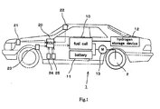
- Fig. 1 is a schematic illustration showing an arrangement of components, such as a fuel cell 10, of the fuel cell system 100 within the vehicle 1.
- the fuel cell 10 is a device that generates power by using hydrogen gas stored in a hydrogen storage device 12 as fuel. Some of power generated by the fuel cell 10 is charged in a battery 11, and a drive motor 13 is driven with power supplied from the fuel cell 10 and the battery 11 to drive drive wheels 2 of the vehicle 1, thus resulting in self-run of the vehicle 1. Note that in Fig. 1 , wirings for electrically connecting the fuel cell 10, the battery 11, and the drive motor 13 are not described in detail.
- Controls to be executed in the vehicle 1 in relation to the fuel cell 10, including control of the odorant addition device according to the present invention, are executed by an ECU 20.
- Various sensors 21 through 25 are also electrically connected to the ECU 20, so that any parameter necessary for control of the fuel cell 10 and control of the odorant addition device that will be described later can be provided to the ECU 20.
- the sensor represented by a reference number of 21 is a hygrothermal sensor 21 that detects temperature and humidity of outside air outside the fuel cell system.
- the sensor represented by a reference number of 22 is a GPS sensor 22 for use with GPS (Global Positioning System), that receives satellite signals to keep track of location of the vehicle 1.
- the sensor represented by a reference number of 23 is an atmospheric pressure sensor 23 that detects atmospheric pressure of outside air outside the fuel cell system.
- the sensor represented by a reference numbers of 24 is a gas component sensor 24 that detects gas (especially gas that acts on olfactory sense of human) component contained in outside air outside the fuel cell system.
- the sensor represented by a reference number of 25 is a wind velocity sensor 25 that detects relative velocity of outside air outside the fuel cell system i.e. wind velocity of outside air relative to the vehicle 1. Note that the wind velocity sensor 25 may alternatively be a vehicle velocity sensor that detects velocity of the vehicle 1 in a relative relationship with wind velocity, rather than directly measuring wind velocity.
- the fuel cell system 100 shown in Fig. 2 is in a state of providing hydrogen gas i.e. fuel gas to the fuel cell 10 in the vehicle 1. Therefore, the fuel cell system 100 is not receiving supply of hydrogen gas from outside, but is in a state of generating power by the fuel cell 10 by supplying hydrogen gas to the cell.
- the fuel cell system 100 shown in Fig. 2 has a fuel cell-use hydrogen tank 120 that is used for temporary storage of hydrogen gas (hereinafter simply referred to as "hydrogen tank", and corresponds to the hydrogen storage device 12 shown in Fig. 1 ).
- the hydrogen tank 120 is a high pressure tank that is capable of storing hydrogen gas in a liquefied state.
- a pressure sensor 26 that detects internal pressure is provided on the hydrogen tank 120. The pressure sensor 26 is capable of measuring remaining amount of hydrogen gas within the hydrogen tank 12 based on the pressure within the tank 120.
- a hydrogen supply channel 102 is connected from the hydrogen tank 120 to the fuel cell 10 and is used for supply of hydrogen gas. Note that an adjustment valve 110 for adjusting flow rate of hydrogen gas is provided to the hydrogen supply channel 102. Further, a hydrogen supply channel 101 is also provided to the hydrogen tank 120, through which hydrogen gas flows when the gas is supplied as fuel from outside the fuel cell system 100. The hydrogen supply channel 101 is indicated with a dotted line in Fig. 2 , since it is not used in the present embodiment.
- An odorant addition device 105 which is used to add odorant to hydrogen gas flowing through the hydrogen supply channel 102, is also provided to this fuel cell system 100. This enables a person around the vehicle 1 to detect leakage of hydrogen gas in the event that hydrogen gas consumed by the fuel cell 10 leaked out of the cell.
- the odorant addition device 105 is composed of: an odorant tank 104 for storing odorant to be added; and an addition valve 103 for adding odorant.
- the ECU 20 which is connected with the various sensors 21 through 25 described above, is also electrically connected to the adjustment valve 110 and the addition valve 103. In this way, addition of odorant is controlled by the odorant addition device 105 at the time when hydrogen gas is supplied from the hydrogen tank 120 to the fuel cell 10 during generation of power by the fuel cell 10.
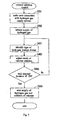
- the odorant addition control in the present embodiment is a routine to be executed by the ECU 20.
- an amount of hydrogen gas necessary for generation of power by the fuel cell 10 is supplied from the hydrogen tank 120.
- opening of the adjustment valve 110 is controlled by the ECU 20 such that an amount of hydrogen gas that corresponds to an amount of power to be output by the fuel cell 10 in response to an operational request from a driver of the vehicle 1 is supplied.
- the routine proceeds to S102.
- the addition valve 103 is controlled by the ECU 20 in order for the odorant addition device 105 to add odorant to hydrogen gas flowing through the hydrogen supply channel 102. Specifically, an amount of odorant that is proportional to the amount of hydrogen flowing through the hydrogen supply channel 102 estimated from the opening of the adjustment value 110 is added. The amount of odorant to be added is calculated by the following Formula 1.
- the diffusional environmental condition refers to an environmental condition that influences state of diffusion of hydrogen gas in outside air at the time when hydrogen gas consumed by the fuel cell 10 leaked out of the device for some reason.
- Different diffusional environmental conditions cause odorant to act differently on olfactory sense of an outside person at the time of hydrogen gas leakage. Therefore, if state of odorant added to hydrogen gas always remains constant, there may be cases of a person being unable to detect leakage of hydrogen gas, or discomfort being brought to a person due to effect of odorant being excessively strong, or the like.
- the diffusional environmental condition is thus detected in S103, in order to make addition of odorant to hydrogen gas more appropriate.
- detection values of the various sensors 21 through 25 are employed in the detection of diffusional environmental condition. Detection by each sensor is described below from the viewpoint of diffusional environmental condition.
- temperature and humidity of outside air detected by the sensor may influence state of diffusion of odorant in hydrogen gas leaked into outside air. For example, the lower the outside air temperature or the lower the outside air humidity, the less the odorant tends to diffuse into outside air, and thus the less easy it becomes for a person to detect leakage of hydrogen gas. The temperature and humidity of outside air are thus detected as the diffusional environmental condition.
- the sensor detects geographical information of the vehicle 1.
- Some geographical condition of the vehicle 1 may influence state of diffusion of odorant in hydrogen gas leaked outside.
- the geographical condition may be an area always windy, a land with low temperatures, or the like, for example, and such an environmental condition may influence state of diffusion of odorant. Since diffusional condition can be detected indirectly from the geographical condition, the detection value of the GPS sensor 22 is adopted as the diffusional environmental condition.
- atmospheric pressure detected by the sensor influences state of diffusion of odorant in hydrogen gas leaked into outside air.
- the lower the atmospheric pressure the less the odorant tends to diffuse into outside air, and thus the less easy it becomes for a person to detect leakage of hydrogen gas.
- the atmospheric pressure is thus detected as the diffusional environmental condition.
- the sensor detects gas components in outside air around the vehicle 1, especially gas components that act on olfactory sense of human. Since odorant acts less on olfactory sense of human in an area with strong odor two some extent, as hot spring area for example, in such a case it may be necessary that odorant diffuses more efficiently. The detection value by the gas component sensor 24 is thus adopted as the diffusional environmental condition.
- the sensor detects velocity of outside air flowing around the vehicle 1, that is, wind velocity. Since wind velocity occurs relatively between outside air and the vehicle 1, it is detected not only when the vehicle 1 is in motion but also when the vehicle 1 is stopped. Since odorant diffuses along with the flow of wind once hydrogen gas is leaked into the outside air, the stronger the wind velocity, the more wide and dilute the odorant diffuses, and thus the less easy it becomes for a person to detect leakage of hydrogen gas. The wind velocity is thus detected as the diffusional environmental condition.
- mode of odorant addition by the odorant addition device 105 is adjusted based on the diffusional environmental condition detected in S103.
- the adjustment of mode of odorant addition is performed by adjusting the amount or odorant to be added from the addition valve as determined by the afore-mentioned Formula 1. Specifically, the following odorant addition coefficient is calculated based on the detection values of the various sensors 21 through 25, and the afore-mentioned Formula 1 is corrected to give the following Formula 2.
- Fig. 4A is an illustration showing a relationship between outside air temperature and odorant addition coefficient ⁇ .
- the odorant addition coefficient ⁇ is calculated based on the outside air temperature detected by the hygrothermal sensor 21.
- the odorant addition coefficient ⁇ is 1 if the outside air temperature is higher than or equal to 0 degrees Celsius, and increases as the temperature decreases to less than 0 degrees Celsius. This is based on consideration that the lower the outside air temperature becomes, the lower the diffusion rate of odorant becomes, and thus the less the odorant acts on olfactory sense of human.
- diffusion rate of odorant can be represented as a product of diffusion coefficient D and concentration gradient of odorant within outside air, while logarithm of the diffusion coefficient D has a linear correlation with respect to inverse of the outside air temperature, as shown in Fig. 4E . Therefore, in order to compensate for decrease in diffusion rate due to decrease in outside air temperature, the amount of odorant to be added from the addition valve 103 may be adjusted so as to increase concentration gradient of odorant, and on that basis, the odorant addition coefficient ⁇ shown in Fig. 4A can be calculated.
- Fig. 4B is an illustration showing a relationship between outside air humidity and odorant addition coefficient ⁇ .
- the odorant addition coefficient ⁇ is calculated based on the outside air humidity detected by the hygrothermal sensor 21.
- the odorant addition coefficient ⁇ is 1 if the outside air humidity is greater than or equal to 50 percent, and becomes a steady-state value larger than 1 as the outside air humidity decreases to less than 50 percent . This is based on consideration that the lower the outside air humidity becomes, the less the odorant acts on olfactory sense of human.
- Fig. 4C is an illustration showing a relationship between atmospheric pressure and odorant addition coefficient ⁇ .
- the odorant addition coefficient ⁇ is calculated based on the atmospheric pressure detected by the atmospheric pressure sensor 23.
- the odorant addition coefficient ⁇ is 1 if the atmospheric pressure is greater than or equal to 1 Atmosphere, and increases as the atmospheric pressure decreases to less than 1 Atmosphere. This is based on consideration that the lower the atmospheric pressure becomes, the less the odorant acts on olfactory sense of human.
- Fig. 4D is an illustration showing a relationship between wind velocity and odorant addition coefficient ⁇ .
- the odorant addition coefficient ⁇ is calculated based on the wind velocity detected by the wind velocity sensor 25.
- the odorant addition coefficient ⁇ is 1 if the wind velocity is less than or equal to 5 m/s, and grows larger as the wind velocity increases to over 5 m/s. This is based on consideration that the more the wind velocity grows, the more quickly the odorant is diluted, and thus the less the odorant acts on olfactory sense of human.
- the odorant addition coefficient may also be set based on the detection value of the gas component sensor 24. For example, if a presence of strong-odor gas is detected around the vehicle 1 by the gas component sensor 24, the odorant addition coefficient may be set to a larger value such that concentration of odorant in hydrogen gas becomes higher, in order not to cause odorant to act less on olfactory sense of human. To the contrary, if neo strong-odor gas is detected around the vehicle 1 by the gas component sensor 24, the odorant addition coefficient may be set to a smaller value such that concentration of odorant in hydrogen gas becomes lower.
- another odorant addition coefficient may be set as an alternative to the odorant addition coefficient described above according to the geographical condition.
- the odorant addition coefficient may be set according to such geographical condition, instead of calculating the odorant addition coefficient 5 based on the detection value of the wind velocity sensor 25.
- the odorant addition coefficient may be set according to such geographical condition, instead of calculating the odorant addition coefficient based on the detection value of the gas component sensor 24. This allows some of the various sensors to be omitted.
- the amount of odorant to be added by the odorant addition device 105 can be adjusted by substituting the odorant addition coefficient set as above into Formula 2. Note that if a plurality of odorant addition coefficients are employed, a product of the respective odorant addition coefficients is substituted into Formula 2. Although a plurality of odorant addition coefficients have been described hereinabove, not all of the odorant addition coefficients are necessarily required, but any one or more of the odorant addition coefficients may be used appropriately as required. In this way, the amount of odorant to be added by the odorant addition device 105 can be adjusted to an amount suitable to the state of diffusion of odorant, so that even if hydrogen gas leaked outside, the leakage thereof can be detected immediately. Once the operation of S104 is complete, the routine proceeds to S105.
- a predetermined velocity V0 As described above based on Fig. 4D , by adjusting the odorant addition coefficient according to the wind velocity, detection of leakage based on odorant can be made more reliable. However, an excessively large wind velocity may result in a pronounced diffusion of odorant, which makes it difficult to detect leakage of hydrogen gas even if the hydrogen gas has odorant added thereto, thus resulting in waste of odorant.
- the threshold value that corresponds to such an excessively large wind velocity is set to V0, and then a judgment is made on whether or not the wind velocity relative to the vehicle 1 of this moment is greater than or equal to this predetermined velocity V0. If it is judged that the wind velocity is greater than or equal to the predetermined velocity V0 in S105, then the routine proceeds to S106, where addition of odorant by the odorant addition device 105 is stopped. In this way, addition of odorant is stopped under such a diffusional environmental condition that no effect of odorant can be expected, so that waste of odorant can be presented.
- S108 a judgment is made on whether or not generation of power by the fuel cell 10 is stopped. That is, a judgment is made on whether or not hydrogen gas needs to be supplied to the fuel cell 10. If it is judged that generation of power is stopped, then the routine proceeds to S109, where addition of odorant by the odorant addition device 105 is stopped. On the other hand, if it is judged that generation of power is not stopped, then the operations from S103 and later are repeated again.
- FIG. 5 is a schematic illustration showing a fuel cell system 100, to which an odorant addition device according to the present embodiment is applied, and a hydrogen gas supply system 200, which supplies hydrogen gas as fuel gas to the fuel cell system, that are in a connected state.
- the fuel cell system 100 since it has a configuration identical to that of the fuel cell system 100 shown in Fig. 2 , the same reference numbers are used and the configuration is not described in detail.
- the hydrogen supply channel 101 is indicated with a dotted line in Fig. 2 , it is indicated with a solid line in Fig. 5 .
- the hydrogen gas supply system 200 has a supply-use hydrogen tank 201 for storing hydrogen gas to be supplied to a gas system.
- the supply-use hydrogen tank 201 is a high pressure tank, like the hydrogen tank 120.
- a hydrogen supply channel 202, through which hydrogen gas to be supplied flows, is connected to the supply-use hydrogen tank 201.
- the channel can be coupled with a hydrogen supply channel 101 on the fuel cell system 100's side via a connecting channel 30.
- an adjustment valve 206 for adjusting flow rate of hydrogen gas flowing therethrough and an odorant addition device 205 for adding odorant of the hydrogen gas are also provided on this hydrogen supply channel 202.
- this odorant addition device 205 is for adding odorant to hydrogen gas for detection of hydrogen gas leakage, and is composed of an odorant tank 204 for storing odorant to be added and an addition valve 203 for adding odorant.
- a supply-side ECU 220 is electrically connected to the adjustment valve 206 and the addition valve 203.
- odorant addition device 205 addition of odorant to hydrogen gas is controlled by the odorant addition device 205 at the time when hydrogen gas is supplied from the hydrogen gas supply system 200 to the fuel cell system 100. Further, when the fuel cell system 100 and the hydrogen gas supply system 200 are connected via the connecting channel 30, the ECU 20 and the supply-side ECU 220 are electrically connected and are allowed to notify each other of a state of their own system.
- the odorant addition device 205 can execute addition of odorant with respect to the fuel gas that is being supplied, so that the hydrogen gas with odorant added can be stored within the hydrogen tank 120.
- the hydrogen gas with odorant added is then supplied from the hydrogen tank 120 to the fuel cell 10, so that generation of power can be executed.
- the odorant addition control by the odorant addition device 205 is now described on Fig. 6 .
- the odorant addition control in the present embodiment is a routine to be executed by the ECU 20 and the ECU 220.
- S201 it is checked whether or not the fuel cell system 100 and the hydrogen gas supply system 200 are in a connected state. As shown in Fig. 5 , the connection is made sure by assuring that the ECU 20 on the fuel cell system 100's side and the supply-side ECU 220 on the hydrogen gas supply system 200's side are in communication. Once the operation of S201 is complete, the routine proceeds to S202.
- S202 supply of hydrogen gas from the hydrogen gas supply system 200 to the fuel cell system 100 is initiated. Specifically, the supply of hydrogen gas is performed by opening the adjustment valve 206 in response to an instruction from the supply-side ECU 220. Along with the initiation of supply of hydrogen gas, addition of odorant by the odorant addition device 205 is also initiated. Once the operation of S202 is complete, the routine proceeds to S203.
- S203 detection of diffusional environmental condition is performed, as with S103 described above. Specifically, results of detections made by various sensors 21 through 25 are passed to the supply-side ECU 220 via the ECU 20. Once the operation of S203 is complete, the routine proceeds to S204.
- mode of odorant addition by the odorant addition device 205 is adjusted based on the diffusional environmental condition detected in S203, as with S104 described above. Therefore, mode of odorant addition is adjusted according to outside air temperature, outside air humidity, and the like at the time when the fuel cell system 100 mounted on the vehicle 1 receives supply of hydrogen gas.
- This predetermined pressure P0 is a tank internal pressure that is obtained when a sufficient amount of hydrogen gas has been supplied into the hydrogen tank 120. If it is judged that the tank internal pressure is greater than or equal to the predetermined pressure P0 in S205, then the routine proceeds to S206, where supply of hydrogen gas from the hydrogen gas supply system 200 and addition of odorant by the odorant addition device 205 are stopped. On the other hand, if it is judged that the tank internal pressure is not greater than or equal to the predetermined pressure P0 in S205, then the operations from S203 and later are performed again.
- addition of odorant is performed at the time when hydrogen gas is supplied to the fuel cell system 100, in the optimal mode based on the diffusional environmental condition that can be taken into consideration at that time of the supply. Therefore, detection of hydrogen gas leakage based on odorant can be performed more reliably even at the time when the hydrogen gas is being consumed by the fuel cell 10.
- a dedicated sensor(s) may also be provided on the hydrogen gas supply system 200's side and the detection of diffusional environmental condition may be performed according to detection value(s) of the sensor(s).
- odorant addition control may also be performed redundantly by the odorant addition device 105 described in the embodiment 1. In this case, it is preferable that addition of odorant by the odorant addition device 105 be performed in consideration of odorant already added to the hydrogen gas by the odorant addition device 205.
- the odorant addition control in the present embodiment is a routine to be executed by the ECU 20 and the supply-side ECU 220, as with the odorant addition control described above. Note that among operations of the odorant addition control shown in Fig. 7 , those identical with the operations of the odorant addition control shown in Fig. 6 and already described above have the same reference numbers, and thus are not described in detail.
- the routine proceeds to S301 after the operation of S202.
- the supply-side ECU 220 detects a history of hydrogen gas consumption in the fuel cell system 100 that is in connection.
- This history of hydrogen gas consumption corresponds to an internal environmental condition of the fuel cell system (hereinafter referred to as "internal environmental condition").
- the internal environmental condition differs from the diffusional environmental condition mentioned above, and is an environmental condition within the fuel cell system that relates to leakage of odorant contained in hydrogen gas to outside the fuel cell system, that is, an environmental condition of the fuel cell system that should be considered at the time of adding odorant to hydrogen gas.
- the history of hydrogen gas consumption in the fuel cell system 100 relates to a level of facility-related deterioration of the fuel cell system 100, which in turn is linked to easiness of detecting leakage of hydrogen gas based on odorant. Therefore, in the present odorant addition control, the history of hydrogen gas consumption is adopted as the internal environmental condition.
- the term "history of hydrogen gas consumption” used herein not only an amount of hydrogen gas consumed by the fuel cell system 100 but also other parameter(s) associated with "history of hydrogen gas consumption " may be employed, such as a running distance and the like of the vehicle 1, for example.
- mode of odorant addition by the odorant addition device 205 is adjusted based on the history of hydrogen gas consumption detected in S301.
- the adjustment of mode of odorant addition is performed by adjusting the odorant addition coefficient in Formula 2, as with S104 and S204 described above.
- mode of odorant addition is adjusted based on a relationship between running distance of the vehicle 1 as the "history of hydrogen gas consumption" and odorant addition coefficient ⁇ , shown in Fig. 8 .
- the odorant addition coefficient ⁇ is set to 1 if the running distance of the vehicle 1 is less than or equal to 30000 kilometers, and is set to 0.5 if the running distance of the vehicle 1 is over 30000 kilometers.
- the odorant addition control in the present embodiment is a routine to be executed by the ECU 20 and the ECU 220, as with the odorant addition control described above. Note that among operations of the odorant addition control shown in Fig. 9 , those identical with the operations of the odorant addition control shown in Fig. 6 and already described above have the same reference numbers, and thus are not described in detail.
- the routine proceeds to S401 after the operation of S202.
- S401 as the internal environmental condition described above, the type of the hydrogen storage device 12 mounted on the fuel cell system 100 is identified.
- the hydrogen storage device 12 is identified as either a high pressure tank or a MH tank that employs hydrogen occlusion alloy.
- the supply-side ECU 220 makes an access to the ECU 20 and identifies the type of the hydrogen tank that corresponds to the hydrogen storage device recognized by the ECU 20 to be on the fuel cell system 100's side.
- a high pressure tank is capable of storing hydrogen gas in a liquefied form, and allows hydrogen gas in the tank to have odorant mixed in advance.
- a MH tank is capable of storing hydrogen gas more safely, but since it is not easy for hydrogen occlusion alloy to store odorant efficiently, it is not allowed to have odorant mixed in hydrogen gas prior to storing the gas into the tank. Therefore, in the present embodiment, the present odorant addition control is performed by recognizing the relationship between hydrogen storage device and odorant as the internal environmental condition.
- mode of odorant addition is adjusted based on the type of the hydrogen storage device 12 identified in S401. Specifically, if the hydrogen storage device 12 is a hydrogen tank 120 of high pressure tank-type as shown is Fig. 5 , then the odorant addition coefficient in Formula 2 is set to 1 and addition of odorant by the odorant addition device 205 is performed. On the other hand, if the hydrogen storage device 12 is a storage device of MH tank-type, then the odorant addition coefficient in Formula 2 is set to zero and addition of odorant by the odorant addition device 205 is not performed. In the latter case, addition of odorant to hydrogen gas is executed by the odorant addition device 105 described above.
- mode of odorant addition is adjusted based on the relationship between odorant and hydrogen storage device of fuel cell system, that is, the storage performance of hydrogen storage device. This allows addition of odorant to be performed in a more suitable state.
- FIG. 10 is an illustration showing a fuel cell system 100 and a hydrogen gas supply system 200 that are in a coupled state.
- Fig. 10 differs from Fig. 5 in its configuration within the hydrogen gas supply system 200. The remaining identical configurations have the same reference numbers and thus are not described in detail.
- the hydrogen gas supply system 200 shown in Fig. 10 also has another supply-use hydrogen tank 211.
- This supply-use hydrogen tank 211 is a high pressure tank, as with the supply-use hydrogen tank 201 .
- the supply-use hydrogen tank 211 is connected to a hydrogen supply channel 202 via a hydrogen supply channel 212.
- no odorant addition device such as an odorant addition device 205 is provided to the hydrogen supply channel 212.
- the hydrogen gas supply system thus configured can supply hydrogen gas stored in either one of the supply-use hydrogen tanks 201, 211 to the fuel cell system 100 in a selective manner according to an instruction from the supply-side ECU 220.
- the odorant addition device 205 adds odorant to hydrogen gas supplied from the supply-use hydrogen tank 201. This allows for selective supply of either hydrogen gas with odorant added or hydrogen gas with no odorant added, from the hydrogen gas supply system 200 to the fuel cell system 100.
- the type of the hydrogen storage device mounted on the fuel cell system 100 is identified by the supply-side ECU 220, and based on the result of identification, a selection is made between supplying hydrogen gas from the supply-use hydrogen tank 201 i.e. supplying hydrogen gas with odorant added to the fuel cell system 100 or supplying hydrogen gas from the supply-use hydrogen tank 211 i.e. supplying hydrogen gas with no odorant added to the fuel cell system 100.
- the hydrogen gas supply system 200 and the fuel cell system 100 can fulfill the same effect as the odorant addition control shown in Fig. 9 .
- odorant may be added by the odorant addition device 105 as the need arises.
- Fig. 11 is a schematic illustration showing a fuel cell system 100, two which an odorant addition device according to the present embodiment is applied, and a hydrogen gas supply system 200, which supplies hydrogen gas as fuel gas to the fuel cell system, that are in a connected state.
- the state of both systems shown in Fig. 11 differs from the state of both systems shown in Fig. 5 in that no odorant addition device 105 is provided on the fuel cell system 100's side and that three odorant addition devices 205, 215, 225 are provided on the hydrogen gas supply system 200's side instead of one odorant addition device 205.
- odorants to be added thereby have different components A, B, C, respectively, and each of the odorant addition devices adds its odorant to hydrogen gas flowing through a hydrogen supply channel 202 according to an instruction from a supply-side ECU 220. Therefore, it is possible to arbitrarily change mix ratio between the odorant components A, B, C in the hydrogen gas to be supplied from the hydrogen gas supply system 200 to the fuel cell system 100.
- the odorant addition devices 205, 215, 225 can execute addition of mixture odorant composed of the three different components with respect to the fuel gas that is being supplied, so that the hydrogen gas with the odorant added can be stored within the hydrogen tank 120.
- the hydrogen gas with the odorant added is then supplied from the hydrogen tank 120 to the fuel cell 10, so that generation of power can be executed.
- odorant addition control to be performed in the hydrogen gas supply system 200 shown in Fig. 11 is described below based on Fig. 12 .
- the odorant addition control in the present embodiment is a routine to be executed by the ECU 20 and the supply-side ECU 220, as with the odorant addition control described above. Note that among operations of the odorant addition control shown in Fig. 12 , those identical with the operations of the odorant addition control shown in Fig. 6 and already described above have the same reference numbers, and thus are not described in detail.
- the routine proceeds to S501 after the operation of S202.
- the supply-side ECU 220 makes an access to the ECU 20 and identifies the type of the fuel cell 10 that is mounted on the fuel cell system 100's side.
- the fuel cell 10 is a polymer electrolyte fuel cell
- durability of the fuel cell 10 against odorant contained in hydrogen gas may vary according to the type of electrolyte, catalyst, and the like used in the cell. That is, there are various possible types of fuel cells that receive supply of hydrogen gas from the hydrogen gas supply system 200, and durability against odorant may vary for each type of fuel cell. This point also needs to be considered sufficiently at the time of adding odorant to hydrogen gas.
- the type of the fuel cell 10 is identified in S501 in order for mode of odorant addition to be in a state that is suitable to durability against odorant of the fuel cell in receipt of hydrogen gas.
- the fuel cell 10 is identified as a fuel cell that belongs to the Case (1) as a result of the operation in S501, then amount of odorant to be added from each odorant addition device is decreased while the afore-mentioned standard mix ratio is maintained, thereby lowering concentration of odorant in the hydrogen gas to 10 ppm, for example. If the fuel cell 10 is identified as a fuel cell that belongs to the Case (2), then amount of odorant to be added from each odorant addition device is increased while the afore-mentioned standard mix ratio is maintained, thereby raising concentration of odorant in the hydrogen gas to 20 ppm, for example.
- the routine proceeds to S503.
- addition of odorant to hydrogen gas can be performed in consideration of difference in the durability of the fuel cell 10 against odorant, so that a good balance can be achieved between longer operating life of the fuel cell 10 and reliable detection of hydrogen gas leakage.
- Fig. 13 is a schematic illustration showing a fuel cell system 100, to which an odorant addition device according to the present embodiment is applied, and a hydrogen gas supply system 200, which supplies hydrogen gas as a fuel gas to the fuel cell system, that are in a connected state.
- the state of both systems shown in Fig. 13 differs from the state of both systems shown in Fig. 5 in that no odorant addition device 205 is provided on the hydrogen gas supply system 200's side and that three odorant addition devices 105, 115, 125 are provided on the fuel cell system 100's side instead of one odorant addition device 105. Further, there are no various sensors 21 through 25 provided on the fuel cell system 100's side.
- odorants to be added thereby have different components A, B, C, respectively, and each of the odorant addition devices adds its odorant to hydrogen gas flowing through a hydrogen supply channel 102 according to an instruction from an ECU 20. Therefore, it is possible to arbitrarily change mix ratio between the odorant components A, B, C in the hydrogen gas to be supplied from the hydrogen tank 120 to the fuel cell 10.
- an odorant addition control regarding adjustment of mode of odorant addition to be performed on the fuel cell system 100's side, when the fuel cell system 100 and the hydrogen gas supply system 200 are connected via a connecting channel 30 and hydrogen gas is being supplied to the fuel cell system 100 will be described based on Fig. 14 .
- the odorant addition control in the present embodiment is a routine to be executed by the ECU 20 and the supply-side ECU 220, as with the odorant addition control described above. Note that among operations of the odorant addition control shown in Fig. 14 , those identical with the operations of the odorant addition control shown in Fig. 6 and already described above have the same reference numbers, and thus are not described in detail.
- the routine proceeds to S601 after the operation of S202.
- locational information of where the hydrogen gas supply system 200 is installed is provided from the supply-side ECU 220 to the ECU 20 of the fuel cell system 100. This locational information is a geographical condition where the hydrogen gas supply system 200 is installed, but may also be used as an environmental condition that may be approximated as the geographical condition of a vehicle 1 that consumes hydrogen gas.
- this locational information is a piece of information that influences diffusion of odorant (as described in Embodiment 1, although the present embodiment differs from Embodiment 1 in that the geographical condition (diffusional environmental condition) is employed on the hydrogen gas supply system's side), a suitable odorant can be added to the extent possible on the fuel cell system 100's side during consumption of hydrogen gas in the vehicle 1.
- this locational information is a piece of information that is stored in advance in memory within the supply-side ECU 220.
- mix ratio between the odorants mixed and added by the odorant addition devices 105, 115, 125 on the fuel cell system 100's side is determined based on the locational information provided in S601. For example, suppose that the vehicle 1 equipped with the fuel cell system 100 is running across a plurality of areas (such as countries, districts, and the like).
- the locational information provided in S601 is a piece of information regarding an area (a)
- the locational information provided in S601 is a piece of information regarding an area (b)
- the routine proceeds to S603.
- S603 a judgment is made on whether or not tank internal pressure within the hydrogen tank 120 detected by a pressure sensor 26 is greater than or equal to a predetermined pressure P0, as with S205. In case of affirmative judgment, the routine proceeds to S604; whereas in case of negative judgment, the operations from S601 and later are performed again. In S604, supply of hydrogen gas from the hydrogen gas supply system 200 to the fuel cell system 100 is stopped. The routine then proceeds to S605, where it is made sure that the hydrogen gas supply system 200 and the fuel cell system 100 are disconnected into a separated state. This allows for generation of power by the fuel cell 10 while the vehicle 1 is in a self-run. Once the operation of S605 is complete, the routine proceeds to S606.
- mix ratio between odorants is determined in the fuel cell system 100 that receives supply of hydrogen gas, based on the locational information of the hydrogen gas supply system 200, so that odorant contained in hydrogen gas to be used in the fuel cell 10 is in a suitable state, which contributes well to more reliable detection of hydrogen gas leakage. Further, in the present control, mode of odorant addition can be adjusted even if no sensor or the like for the detection of environmental condition is provided on the fuel cell system 100's side.
Landscapes
- Chemical & Material Sciences (AREA)
- Engineering & Computer Science (AREA)
- Chemical Kinetics & Catalysis (AREA)
- Organic Chemistry (AREA)
- General Chemical & Material Sciences (AREA)
- Sustainable Energy (AREA)
- Sustainable Development (AREA)
- Electrochemistry (AREA)
- Life Sciences & Earth Sciences (AREA)
- Manufacturing & Machinery (AREA)
- Oil, Petroleum & Natural Gas (AREA)
- Combustion & Propulsion (AREA)
- Inorganic Chemistry (AREA)
- Fuel Cell (AREA)
- Physics & Mathematics (AREA)
- General Physics & Mathematics (AREA)
- Hydrogen, Water And Hydrids (AREA)
Applications Claiming Priority (2)
| Application Number | Priority Date | Filing Date | Title |
|---|---|---|---|
| JP2007110327A JP4905235B2 (ja) | 2007-04-19 | 2007-04-19 | 付臭剤添加装置、燃料ガス供給システム |
| PCT/JP2008/057098 WO2008133022A1 (ja) | 2007-04-19 | 2008-04-10 | 付臭剤添加装置および燃料ガス供給システム |
Publications (2)
| Publication Number | Publication Date |
|---|---|
| EP2149596A1 true EP2149596A1 (de) | 2010-02-03 |
| EP2149596A4 EP2149596A4 (de) | 2013-01-02 |
Family
ID=39925481
Family Applications (1)
| Application Number | Title | Priority Date | Filing Date |
|---|---|---|---|
| EP08740199A Withdrawn EP2149596A4 (de) | 2007-04-19 | 2008-04-10 | Odoranszugabevorrichtung und brennstoffgaszufuhrvorrichtung |
Country Status (6)
| Country | Link |
|---|---|
| US (1) | US9028570B2 (de) |
| EP (1) | EP2149596A4 (de) |
| JP (1) | JP4905235B2 (de) |
| KR (1) | KR101138929B1 (de) |
| CN (1) | CN101663380B (de) |
| WO (1) | WO2008133022A1 (de) |
Cited By (1)
| Publication number | Priority date | Publication date | Assignee | Title |
|---|---|---|---|---|
| WO2017153682A1 (fr) * | 2016-03-08 | 2017-09-14 | Engie | Dispositif et procédé d'odorisation d'un gaz en circulation dans une canalisation |
Families Citing this family (18)
| Publication number | Priority date | Publication date | Assignee | Title |
|---|---|---|---|---|
| JP5270076B2 (ja) * | 2006-07-20 | 2013-08-21 | トヨタ自動車株式会社 | 車載水素貯蔵装置 |
| JP5643887B2 (ja) * | 2013-10-09 | 2014-12-17 | 本田技研工業株式会社 | 燃料電池システム |
| KR101679927B1 (ko) * | 2014-12-09 | 2016-12-06 | 현대자동차주식회사 | 전기자동차용 냉각 시스템 및 그 방법 |
| US11731633B2 (en) * | 2017-09-15 | 2023-08-22 | Cummins Inc. | Vehicle loss calculation for improved fuel economy |
| KR102260206B1 (ko) * | 2018-11-27 | 2021-06-03 | 이나연 | 광촉매를 구비한 수소 연료 변환기 |
| US11881093B2 (en) | 2020-08-20 | 2024-01-23 | Denso International America, Inc. | Systems and methods for identifying smoking in vehicles |
| US11760169B2 (en) | 2020-08-20 | 2023-09-19 | Denso International America, Inc. | Particulate control systems and methods for olfaction sensors |
| US11828210B2 (en) | 2020-08-20 | 2023-11-28 | Denso International America, Inc. | Diagnostic systems and methods of vehicles using olfaction |
| US11932080B2 (en) | 2020-08-20 | 2024-03-19 | Denso International America, Inc. | Diagnostic and recirculation control systems and methods |
| US12017506B2 (en) | 2020-08-20 | 2024-06-25 | Denso International America, Inc. | Passenger cabin air control systems and methods |
| US12251991B2 (en) | 2020-08-20 | 2025-03-18 | Denso International America, Inc. | Humidity control for olfaction sensors |
| US12269315B2 (en) | 2020-08-20 | 2025-04-08 | Denso International America, Inc. | Systems and methods for measuring and managing odor brought into rental vehicles |
| US11760170B2 (en) | 2020-08-20 | 2023-09-19 | Denso International America, Inc. | Olfaction sensor preservation systems and methods |
| US11636870B2 (en) | 2020-08-20 | 2023-04-25 | Denso International America, Inc. | Smoking cessation systems and methods |
| US11813926B2 (en) | 2020-08-20 | 2023-11-14 | Denso International America, Inc. | Binding agent and olfaction sensor |
| US12377711B2 (en) | 2020-08-20 | 2025-08-05 | Denso International America, Inc. | Vehicle feature control systems and methods based on smoking |
| CN117432946B (zh) * | 2023-12-19 | 2024-03-08 | 上海叁零肆零科技有限公司 | 结合仿真的梯度分布式城镇燃气智能加臭方法及系统 |
| CN118242564B (zh) * | 2024-05-28 | 2024-07-16 | 普利莱(天津)燃气设备有限公司 | 一种智能自适应天然气加臭剂浓度控制系统和控制方法 |
Family Cites Families (11)
| Publication number | Priority date | Publication date | Assignee | Title |
|---|---|---|---|---|
| US3169839A (en) * | 1959-09-23 | 1965-02-16 | George W Benz | Odorizing of liquified gas |
| GB1181426A (en) * | 1963-01-14 | 1970-02-18 | Packo Joseph J | Visual Identification of normally Colorless Fuel Gas |
| JPS59219392A (ja) | 1983-05-27 | 1984-12-10 | Tokyo Gas Eng Kk | ガスに対する付臭方法及びその装置 |
| US5167867A (en) * | 1989-09-26 | 1992-12-01 | Exxon Production Research Company | Test-fluid composition and method for detecting leaks in pipelines and associated facilities |
| CN1090636A (zh) * | 1993-01-13 | 1994-08-10 | 中国市政工程华北设计院煤气设计研究所 | 燃气半自动加臭方法及其专用装置 |
| JPH10115587A (ja) | 1996-10-11 | 1998-05-06 | Osaka Gas Co Ltd | 付臭剤濃度の測定方法 |
| US20010047621A1 (en) * | 1999-06-29 | 2001-12-06 | Joe Frank Arnold | Injection system and method for odorizing natural gas |
| JP2002029701A (ja) * | 2000-07-10 | 2002-01-29 | Toyota Motor Corp | 水素供給装置および該水素供給装置を備える燃料電池装置、並びに水素検出方法 |
| JP4023731B2 (ja) | 2002-09-18 | 2007-12-19 | 本田技研工業株式会社 | 水素供給装置 |
| WO2005010427A1 (ja) | 2003-07-25 | 2005-02-03 | Toyota Jidosha Kabushiki Kaisha | ガス供給装置 |
| JP5055883B2 (ja) * | 2005-09-07 | 2012-10-24 | トヨタ自動車株式会社 | 水素供給装置 |
-
2007
- 2007-04-19 JP JP2007110327A patent/JP4905235B2/ja not_active Expired - Fee Related
-
2008
- 2008-04-10 CN CN2008800126479A patent/CN101663380B/zh not_active Expired - Fee Related
- 2008-04-10 WO PCT/JP2008/057098 patent/WO2008133022A1/ja not_active Ceased
- 2008-04-10 US US12/450,890 patent/US9028570B2/en not_active Expired - Fee Related
- 2008-04-10 KR KR1020097023907A patent/KR101138929B1/ko not_active Expired - Fee Related
- 2008-04-10 EP EP08740199A patent/EP2149596A4/de not_active Withdrawn
Cited By (3)
| Publication number | Priority date | Publication date | Assignee | Title |
|---|---|---|---|---|
| WO2017153682A1 (fr) * | 2016-03-08 | 2017-09-14 | Engie | Dispositif et procédé d'odorisation d'un gaz en circulation dans une canalisation |
| FR3048623A1 (fr) * | 2016-03-08 | 2017-09-15 | Engie | Dispositif et procede d'odorisation d'un gaz en circulation dans une canalisation |
| CN109153032A (zh) * | 2016-03-08 | 2019-01-04 | 前苏伊士环能集团 | 用于管道中循环气体加臭的设备和方法 |
Also Published As
| Publication number | Publication date |
|---|---|
| CN101663380A (zh) | 2010-03-03 |
| JP2008266436A (ja) | 2008-11-06 |
| KR20090129519A (ko) | 2009-12-16 |
| CN101663380B (zh) | 2013-02-13 |
| KR101138929B1 (ko) | 2012-04-25 |
| EP2149596A4 (de) | 2013-01-02 |
| US9028570B2 (en) | 2015-05-12 |
| JP4905235B2 (ja) | 2012-03-28 |
| US20100101306A1 (en) | 2010-04-29 |
| WO2008133022A1 (ja) | 2008-11-06 |
Similar Documents
| Publication | Publication Date | Title |
|---|---|---|
| EP2149596A1 (de) | Odoranszugabevorrichtung und brennstoffgaszufuhrvorrichtung | |
| US20190372141A1 (en) | Controller for estimating relative humidity and condensed water, and method for controlling condensed water drain using the same | |
| EP1966846B9 (de) | Brennstoffzellensystem, mit brennstoffzellensystem ausgestattetes bewegliches objekt und abnormitätsbeurteilungsverfahren für ein brennstoffzellensystem | |
| KR101190170B1 (ko) | 연료전지시스템 | |
| WO2008023503A1 (en) | Fuel cell system and method of diagnosing on-off valve | |
| JP4962777B2 (ja) | ガス供給システム | |
| US20120070757A1 (en) | Fuel cell vehicle | |
| KR101575330B1 (ko) | 연료전지 차량의 응축수 배출 시스템 및 그 비상 제어 방법 | |
| JP2002352824A (ja) | 燃料電池システム | |
| WO2008099905A1 (ja) | 燃料電池システム | |
| EP2012385A1 (de) | Brennstoffzellensystem und fahrzeug mit dem brennstoffzellensystem | |
| WO2008069111A1 (ja) | 燃料電池システム | |
| US7736814B2 (en) | Fuel-cell system and method of estimating nitrogen concentration on fuel electrode of fuel cell | |
| US8076036B2 (en) | Fuel cell system, operation method thereof, and fuel cell vehicle | |
| US9059438B2 (en) | Fuel cell system | |
| JP5199645B2 (ja) | 燃料電池システム | |
| JP4736612B2 (ja) | 移動体 | |
| US8067125B2 (en) | Fuel cell system and its operation stop method | |
| JP2006140132A (ja) | 燃料供給装置 | |
| US8080342B2 (en) | Fuel cell system | |
| JP2007227058A (ja) | 燃料電池システムおよび燃料電池システムの制御方法 | |
| JP4744188B2 (ja) | 燃料電池車の制御装置 | |
| JP2005347190A (ja) | 移動体および燃料補給施設 | |
| JP4998695B2 (ja) | 燃料電池システム |
Legal Events
| Date | Code | Title | Description |
|---|---|---|---|
| PUAI | Public reference made under article 153(3) epc to a published international application that has entered the european phase |
Free format text: ORIGINAL CODE: 0009012 |
|
| 17P | Request for examination filed |
Effective date: 20091119 |
|
| AK | Designated contracting states |
Kind code of ref document: A1 Designated state(s): AT BE BG CH CY CZ DE DK EE ES FI FR GB GR HR HU IE IS IT LI LT LU LV MC MT NL NO PL PT RO SE SI SK TR |
|
| AX | Request for extension of the european patent |
Extension state: AL BA MK RS |
|
| DAX | Request for extension of the european patent (deleted) | ||
| A4 | Supplementary search report drawn up and despatched |
Effective date: 20121204 |
|
| RIC1 | Information provided on ipc code assigned before grant |
Ipc: C10L 3/10 20060101AFI20121128BHEP Ipc: C01B 3/00 20060101ALI20121128BHEP Ipc: H01M 8/04 20060101ALI20121128BHEP Ipc: H01M 8/06 20060101ALI20121128BHEP Ipc: C10L 3/00 20060101ALI20121128BHEP |
|
| RAP1 | Party data changed (applicant data changed or rights of an application transferred) |
Owner name: TOYOTA JIDOSHA KABUSHIKI KAISHA |
|
| 17Q | First examination report despatched |
Effective date: 20150623 |
|
| STAA | Information on the status of an ep patent application or granted ep patent |
Free format text: STATUS: THE APPLICATION IS DEEMED TO BE WITHDRAWN |
|
| 18D | Application deemed to be withdrawn |
Effective date: 20151104 |