EP2149647A2 - Tuile - Google Patents
Tuile Download PDFInfo
- Publication number
- EP2149647A2 EP2149647A2 EP09009605A EP09009605A EP2149647A2 EP 2149647 A2 EP2149647 A2 EP 2149647A2 EP 09009605 A EP09009605 A EP 09009605A EP 09009605 A EP09009605 A EP 09009605A EP 2149647 A2 EP2149647 A2 EP 2149647A2
- Authority
- EP
- European Patent Office
- Prior art keywords
- roof
- roof tile
- outer skin
- insulating body
- top surface
- Prior art date
- Legal status (The legal status is an assumption and is not a legal conclusion. Google has not performed a legal analysis and makes no representation as to the accuracy of the status listed.)
- Withdrawn
Links
- 239000004033 plastic Substances 0.000 claims abstract description 23
- 229920003023 plastic Polymers 0.000 claims abstract description 23
- 239000006260 foam Substances 0.000 claims abstract description 19
- 238000009413 insulation Methods 0.000 claims abstract description 9
- 238000004519 manufacturing process Methods 0.000 claims abstract description 5
- 229920002635 polyurethane Polymers 0.000 claims abstract description 5
- 239000004814 polyurethane Substances 0.000 claims abstract description 5
- 229920000582 polyisocyanurate Polymers 0.000 claims abstract 3
- 239000011495 polyisocyanurate Substances 0.000 claims abstract 3
- 239000011521 glass Substances 0.000 claims description 5
- 238000010276 construction Methods 0.000 claims description 4
- 239000002131 composite material Substances 0.000 claims description 3
- 239000011248 coating agent Substances 0.000 claims description 2
- 238000000576 coating method Methods 0.000 claims description 2
- 239000007788 liquid Substances 0.000 claims description 2
- 230000000284 resting effect Effects 0.000 claims 1
- 238000000034 method Methods 0.000 abstract description 2
- 239000011449 brick Substances 0.000 description 9
- 229910052751 metal Inorganic materials 0.000 description 5
- 239000002184 metal Substances 0.000 description 5
- XLYOFNOQVPJJNP-UHFFFAOYSA-N water Substances O XLYOFNOQVPJJNP-UHFFFAOYSA-N 0.000 description 5
- 238000005187 foaming Methods 0.000 description 4
- 230000001070 adhesive effect Effects 0.000 description 3
- 239000012530 fluid Substances 0.000 description 3
- 239000012212 insulator Substances 0.000 description 3
- 239000000463 material Substances 0.000 description 3
- 239000000853 adhesive Substances 0.000 description 2
- 239000004020 conductor Substances 0.000 description 2
- 239000003381 stabilizer Substances 0.000 description 2
- 230000007704 transition Effects 0.000 description 2
- 239000004604 Blowing Agent Substances 0.000 description 1
- YLEIFZAVNWDOBM-ZTNXSLBXSA-N ac1l9hc7 Chemical compound C([C@H]12)C[C@@H](C([C@@H](O)CC3)(C)C)[C@@]43C[C@@]14CC[C@@]1(C)[C@@]2(C)C[C@@H]2O[C@]3(O)[C@H](O)C(C)(C)O[C@@H]3[C@@H](C)[C@H]12 YLEIFZAVNWDOBM-ZTNXSLBXSA-N 0.000 description 1
- 239000012190 activator Substances 0.000 description 1
- 229910052782 aluminium Inorganic materials 0.000 description 1
- XAGFODPZIPBFFR-UHFFFAOYSA-N aluminium Chemical compound [Al] XAGFODPZIPBFFR-UHFFFAOYSA-N 0.000 description 1
- 239000000919 ceramic Substances 0.000 description 1
- 238000006243 chemical reaction Methods 0.000 description 1
- 230000001419 dependent effect Effects 0.000 description 1
- 230000000694 effects Effects 0.000 description 1
- 239000004744 fabric Substances 0.000 description 1
- 230000009970 fire resistant effect Effects 0.000 description 1
- 239000003063 flame retardant Substances 0.000 description 1
- 239000004872 foam stabilizing agent Substances 0.000 description 1
- 239000003365 glass fiber Substances 0.000 description 1
- 239000012948 isocyanate Substances 0.000 description 1
- 150000002513 isocyanates Chemical class 0.000 description 1
- 230000013011 mating Effects 0.000 description 1
- 230000002093 peripheral effect Effects 0.000 description 1
- 239000000575 pesticide Substances 0.000 description 1
- 229920005862 polyol Polymers 0.000 description 1
- 150000003077 polyols Chemical class 0.000 description 1
- 230000005855 radiation Effects 0.000 description 1
- 238000007789 sealing Methods 0.000 description 1
- 239000007858 starting material Substances 0.000 description 1
- 239000011800 void material Substances 0.000 description 1
Images


Classifications
-
- E—FIXED CONSTRUCTIONS
- E04—BUILDING
- E04D—ROOF COVERINGS; SKY-LIGHTS; GUTTERS; ROOF-WORKING TOOLS
- E04D1/00—Roof covering by making use of tiles, slates, shingles, or other small roofing elements
- E04D1/28—Roofing elements comprising two or more layers, e.g. for insulation
-
- E—FIXED CONSTRUCTIONS
- E04—BUILDING
- E04D—ROOF COVERINGS; SKY-LIGHTS; GUTTERS; ROOF-WORKING TOOLS
- E04D1/00—Roof covering by making use of tiles, slates, shingles, or other small roofing elements
- E04D1/29—Means for connecting or fastening adjacent roofing elements
- E04D1/2907—Means for connecting or fastening adjacent roofing elements by interfitted sections
- E04D1/2956—Means for connecting or fastening adjacent roofing elements by interfitted sections having tongues and grooves
-
- F—MECHANICAL ENGINEERING; LIGHTING; HEATING; WEAPONS; BLASTING
- F24—HEATING; RANGES; VENTILATING
- F24S—SOLAR HEAT COLLECTORS; SOLAR HEAT SYSTEMS
- F24S20/00—Solar heat collectors specially adapted for particular uses or environments
- F24S20/60—Solar heat collectors integrated in fixed constructions, e.g. in buildings
- F24S20/69—Solar heat collectors integrated in fixed constructions, e.g. in buildings in the form of shingles or tiles
-
- Y—GENERAL TAGGING OF NEW TECHNOLOGICAL DEVELOPMENTS; GENERAL TAGGING OF CROSS-SECTIONAL TECHNOLOGIES SPANNING OVER SEVERAL SECTIONS OF THE IPC; TECHNICAL SUBJECTS COVERED BY FORMER USPC CROSS-REFERENCE ART COLLECTIONS [XRACs] AND DIGESTS
- Y02—TECHNOLOGIES OR APPLICATIONS FOR MITIGATION OR ADAPTATION AGAINST CLIMATE CHANGE
- Y02B—CLIMATE CHANGE MITIGATION TECHNOLOGIES RELATED TO BUILDINGS, e.g. HOUSING, HOUSE APPLIANCES OR RELATED END-USER APPLICATIONS
- Y02B10/00—Integration of renewable energy sources in buildings
- Y02B10/20—Solar thermal
-
- Y—GENERAL TAGGING OF NEW TECHNOLOGICAL DEVELOPMENTS; GENERAL TAGGING OF CROSS-SECTIONAL TECHNOLOGIES SPANNING OVER SEVERAL SECTIONS OF THE IPC; TECHNICAL SUBJECTS COVERED BY FORMER USPC CROSS-REFERENCE ART COLLECTIONS [XRACs] AND DIGESTS
- Y02—TECHNOLOGIES OR APPLICATIONS FOR MITIGATION OR ADAPTATION AGAINST CLIMATE CHANGE
- Y02E—REDUCTION OF GREENHOUSE GAS [GHG] EMISSIONS, RELATED TO ENERGY GENERATION, TRANSMISSION OR DISTRIBUTION
- Y02E10/00—Energy generation through renewable energy sources
- Y02E10/40—Solar thermal energy, e.g. solar towers
Definitions
- the invention relates to a roof tile with a, in particular metallic, weather-resistant outer skin, which at least partially covers the top surface of the tile and mit stricture in roofing, and a foam plastic existing insulating body for thermal insulation of the roof structure, wherein the insulating body is foamed to the outer skin and forms a mechanical bond with this.
- the US 4,233,962 shows a solar roof tile, wherein in a kind of metal box, for example, polyurethane is injected, whereby a kind of insulating foam body is formed.
- a kind of metal box for example, polyurethane is injected, whereby a kind of insulating foam body is formed.
- This foam body is completely surrounded by the metal box and thus when placed on a roof construction forms a thermal or cold bridge toward the roof structure, whereby the insulating properties of the foam body is counteracted.
- the object of the invention is to provide a comparison with the prior art improved roof tiles with insulating or improved production possibility for such a tile. Furthermore, the tile should be as multifunctional and applicable for a variety of applications. The production of different shapes should be simplified in order to produce cost-effectively roof tiles with insulating.
- the roof tile according to the invention characterized in that the insulating body is on its side facing away from the top surface free of the weather-resistant outer skin.
- no Wäre- or cold bridge is formed which extends to the roof construction. It can rather be arranged by juxtaposing several roof tiles a particularly good and continuous insulation effect can be achieved.
- the insulating body with its exposed side directly on a roof construction flush mounted can be arranged.
- the advantage of foaming is that the insulating body does not have to be preformed or prefoamed, which would often lead to the problem that the prefoamed body is not exactly adaptable to the brick forming the outer skin. Also, it is not absolutely necessary in this case to connect the insulating body and the outer skin by an additional adhesive or thermally.
- the foam plastic is preferably made of polyurethane.
- the outer skin In order to improve the adhesive properties, provision can be made for the outer skin to be provided with a coating in the areas in contact with the foam plastic, in particular surface-treated with an adhesion primer.
- the outer skin extends at least substantially over the entire top surface of the roof tile.
- the outer skin is frame-shaped and leaves the central region of the top surface of the roof tile free, so that, for example, in the central region of the top surface of the roof tile a preferably transparent plate, preferably a glass, composite or plastic plate arranged is, which forms the umbrella in the roof structure.
- the preferably metallic outer skin continues below the transparent plate.
- the entire outer skin can be foamed substantially continuously in the upper region of the insulating body, wherein it forms the same outer shape.
- the outer skin is formed integrally with a preferably metallic, inner inner layer.
- the frame-shaped area forms the weather-resistant outer skin, while the inner area as a boundary between the einbringbaren Solar elements and the insulating body is used.
- the outer skin of various materials such as plastic, ceramic, metal, glass fiber reinforced plates, etc. may be formed.
- the insulating body can form a trough on its side facing the top surface of the tile, wherein in the tub at least one pipe for a liquid can be arranged and / or in the central region of the top surface of the tile, if necessary below the transparent plate, at least one photovoltaic element can be arranged.
- the insulating body may have at least one groove and at least one spring, which are designed and arranged such that the insulating body of the roof tiles in the roof structure enter into a water-impermeable tongue and groove connection and the top surface of the roof tiles continuously forms the outer skin of the roof structure.
- Protection is also desired for a roof structure of several roof tiles, wherein a plurality of roof tiles has an at least substantially over the entire top surface of the tile extending outer skin and wherein at least one of the tiles according to one of claims 8 to 10 is formed.
- the roof structure may be earthed via electrically conductive fastening means connecting two roof tiles and one grounding line.
- Another aspect of the invention provides a method for producing a roof tile, wherein the roof tile has a particular metallic, weather-resistant outer skin and an insulating body, wherein the outer skin is inserted into a mold and the mold is filled with foam plastic. During curing of the foamed plastic, a bond between outer skin becomes and foam plastic, which forms the basis for the multifunctionality of the tile.
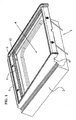
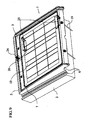
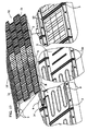
- Fig. 1 generally shows a roof tile 1, consisting of the insulating body 2, in which the trough 4 is formed.
- the outer skin 3 is formed in a frame shape around the tub 4 and the upper edge of the tub or foamed.
- the insulating body 2 has correspondingly a spring 5 and a groove 6, which allow the juxtaposition of roof tiles 1.
- the trough 4 of the insulating body 2 is already below the paragraph 11 of the outer skin 3 one of several possible openings 13 (here bore) shown, which is provided for the attachment of connections for pipelines.
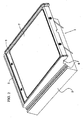
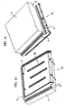
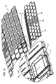
- a roof tile 1 is shown, in which a preferably transparent plate 7 is applied to the shoulder 11 of the outer skin 3 and the trough 4 covers.
- the roof tile is designed as a conductive brick 1a, wherein in the pipes 9 fluid 21 can flow.
- the plate 7 is in this case designed as solar glass, which optimizes the solar radiation to the pipes 9.
- Reference 14 indicates the pipe connections, wherein the pipes 9 are partially guided through the passage opening 13.
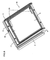
- Fig. 4 shows the conductor brick 1a from below, wherein it is shown that 1 water drainage channels 41 may be formed on the underside of the insulating body 2 and at the bottom of the entire tile, which can dissipate condensate or undesired penetrated water. In the roof structure 32, these groove or channel-shaped water drainage channels 41 can form a continuous network.
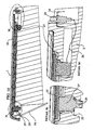
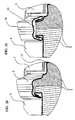
- Fig. 5 shows sectional views of overlapping bricks 1a, wherein in detail A, the transition of the pipe 9 is shown by a tile 1a to the adjacent tile 1a.
- the sealing end piece 15 is connected to the pipe 9 of the next roof tile 1 to form a pipe connection 14 with seal 16.
- the actual solar element here consists of the collector 22, the collector insulation 17 and the pipe 9 guided therein, which are arranged in the trough 4 of the roof tile 1a below the preferably transparent plate 7.
- the collector insulation 17 may also be formed in the form of a vacuum or a vacuum pan or vacuum chamber.
- the attachment of the roof tiles 1a by means of fasteners / screws 19 is shown, which may be attached to any position of the tile 1, in particular along the peripheral edge.
- Detail A also shows a strain compensator 18 which can compensate for the different expansions of the materials at possible high temperatures in the pipeline 9.
- This expansion compensator 18 may be arranged in the entire region of the pipes 9, but preferably in the region of the pipe connections 14.
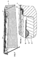
- a sectional drawing of a tile or line tile 1a is shown, wherein in the right area of the pipe connection 14 can be seen.
- the collector 22 can be seen, which in this case is designed as a cast plate which contains the pipe 9 with the fluid 21 contained therein.
- the collector 22 is connected to the collector insulation 17, which are arranged together in the trough 4 of the insulating body 2.
- the plate 7 is connected in the region of the paragraph 11 above the elastic and adhesive material 12 with the outer skin 3.
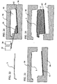
- Fig. 6 ' with the detail C ' shows a tile 1a, in which the preferably metallic outer skin 3 is continuously mounted above the insulating body 2 or foamed on this.
- the insulating body 2 together with the outer skin 3 can be made standardized, after which the corresponding inserts can be used in the trough-shaped recess.
- the outer skin 3 forms not only in the frame area the concrete outer cover but also in the central region of the roof tile 1 an inner layer which protects the insulating body 2 from weathering and other influences continuously in the deck area.
- Fig. 7 and Detail J show an alternative embodiment of a line tile 1c, wherein the pipe 9 is formed by two metal and / or plastic plates 2.3 partially connected to each other, which guide a preferably meandered fluid 21 in a through the metal and / or plastic plates 23 Channel allowed.
- an insulating vacuum in the region of the PV element can be formed in a similar manner.
- Fig. 8 shows a roof tile 1, which is designed as a photovoltaic (PV) brick 1b.
- PV photovoltaic
- an electrical recess 25 is additionally provided in the insulating body 2 in the tub 4.
- the outer skin 3 is applied or foamed around the trough 4 like a frame, wherein in the example shown a plug holder 24 is integrated.
- Fig. 9 shows for this purpose that the plug holder 24 is connected via a plug cable 26 with the electronics recess 25.
- photovoltaic elements 10 are arranged in the tub 4.
- Fig. 10 is to see in the cross section of the PV bricks 1b with photovoltaic element 10, which is arranged in the region of the trough 4 and wherein the electrical connections 27 which are arranged in the electrical recesses 25 form the contact point of the photovoltaic element 10 with the circuit.
- the detail N shows the first electrical connection 27, with the plug receptacle 29.
- the matching plug 28 is shown in detail M, which is in the plug holder 24 is attached and connected via the connector cable 26 with a second electrical connection 27.
- Fig. 11 shows a roof tile 1, which is designed as Lichteinlassziegel 1c.
- the insulating body 2 on an opening 8, which is bounded above and below by a plate 7, which may be embodied for example as insulating or solar control glass.
- Fig. 12 is a cross section of this Lichteinlassziegels 1c to see, it can be seen in detail K that the inner lining 30 is guided to the support frame 31.
- a shoulder 11 can be arranged, to which the lower (glass) plate 7 can be attached via an elastic element 12.
- the detail L with the upper preferably transparent plate. 7
- FIGS. 13 and 14 show a trough-free roof tile 1d, in which the insulating body 2 is foamed to the outer skin 3, wherein the outer skin can have stiffening ribs 39 in any desired configuration.
- the possibility of the tongue and groove connection can be seen.
- the provision of water drainage channels 41 is possible here.
- the Fig. 15 shows further connection variants of roof tiles 1 with the fixing screw 19, which can serve the grounding.
- Fig. 16 shows an umbrella 32, which consists of different roof tile types.
- conductive tiles 1a, PV tiles 1b and troughless roof tiles 1d are provided.
- whole end tiles 1h and half end tiles 1i are arranged on the edge of the roof surface.
- Fig. 17 is the multi-functionality of the present invention very well recognizable, the different brick types 1a, 1b, 1c (see Fig. 18 ) and 1d in any combination can be arranged side by side.
- R is again the transition between the pipes 9 via the pipe connection 14th seen.
- trough-free roof tiles 1d and conductor tiles 1a can be seen side by side, while in detail T, the PV tiles 1b are shown with their photovoltaic elements 10, which are arranged below a transparent plate 7.
- Lichteinlassziegel 1c are integrated into the roof structure.
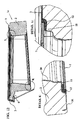
- Fig. 19 shows the mating overlap areas between the individual partially different roof tiles, which are arranged on a roof structure 33. From the overlapping details U, V and W shows that the insulating body 2 does not come directly into contact with the weather, whereby the insulator 2 different roof tiles 1 a tight connection, even through the folded ends of the outer skin 3, received.
- Fig. 21 contrasts an alternative variant of the overlap region Fig. 20 in this Fig. 21 a connecting strip 34 is hooked or clamped in the folded ends of the outer skin 3, wherein between the insulating body 2 and connecting bar 34, a void 35 may remain. Both variants are possible with or without empty space 35.
- Fig. 22 shows the outer skin 3, which may be formed both continuous and frame-shaped.
- This outer skin 3 and, if necessary, the Formstabitisator 42 is applied to the corresponding mold 36. Subsequently, as in Fig. 24 closed, the mold 36 is closed, after which the starting materials for the foam plastic mass are brought into the cavity 40.
- the foam plastic compound 2a is thereby formed by polyol 37 and isocyanate 38 and optionally blowing agents and other auxiliaries such as water, activators, foam stabilizers, flame retardants, pesticides, etc.
- the insulating body 2 may be constructed in layers. Above all, a shape stabilizer 42 can be arranged on the underside, but also in the side regions of the insulating body 2. This may be in the form of a plate, a film, a fabric, a non-woven, a fire-resistant plasterboard, an aluminum plate or the like.
- the shape stabilizer 42 can already during the AnInumvorganges inserted into the mold 36 or even attached to the insulator 2. It can have different functions, but above all serves to reduce or compensate for (tensile) stresses during and / or after foaming in the mold 36.
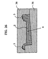
- Fig. 26 shows suitably the design of the mold 36 when the outer skin 3 is frame-shaped introduced into the mold 36, wherein the part of the mold 36 through the frame of the outer skin 3 is the negative part of the trough 4 of the insulating body 2 to be formed.
Landscapes
- Engineering & Computer Science (AREA)
- Architecture (AREA)
- Civil Engineering (AREA)
- Structural Engineering (AREA)
- Physics & Mathematics (AREA)
- Life Sciences & Earth Sciences (AREA)
- Sustainable Development (AREA)
- Sustainable Energy (AREA)
- Thermal Sciences (AREA)
- Chemical & Material Sciences (AREA)
- Combustion & Propulsion (AREA)
- Mechanical Engineering (AREA)
- General Engineering & Computer Science (AREA)
- Roof Covering Using Slabs Or Stiff Sheets (AREA)
Applications Claiming Priority (1)
| Application Number | Priority Date | Filing Date | Title |
|---|---|---|---|
| AT0117108A AT506959B1 (de) | 2008-07-29 | 2008-07-29 | Dachziegel |
Publications (2)
| Publication Number | Publication Date |
|---|---|
| EP2149647A2 true EP2149647A2 (fr) | 2010-02-03 |
| EP2149647A3 EP2149647A3 (fr) | 2015-12-02 |
Family
ID=41203775
Family Applications (1)
| Application Number | Title | Priority Date | Filing Date |
|---|---|---|---|
| EP09009605.8A Withdrawn EP2149647A3 (fr) | 2008-07-29 | 2009-07-24 | Tuile |
Country Status (2)
| Country | Link |
|---|---|
| EP (1) | EP2149647A3 (fr) |
| AT (1) | AT506959B1 (fr) |
Cited By (6)
| Publication number | Priority date | Publication date | Assignee | Title |
|---|---|---|---|---|
| WO2011080169A3 (fr) * | 2009-12-22 | 2012-05-10 | Fraunhofer Gesellschaft zur Förderung der angewandten Forschung e.V. | Élément de construction |
| US20150354217A1 (en) * | 2013-02-21 | 2015-12-10 | Sunscape Systems Ltd | Roof tile system |
| WO2017072345A1 (fr) * | 2015-10-28 | 2017-05-04 | Fraunhofer-Gesellschaft zur Förderung der angewandten Forschung e.V. | Collecteur thermique solaire et/ou isolation destinée à l'intégraion dans une enveloppe de bâtiment |
| CN108678291A (zh) * | 2018-07-06 | 2018-10-19 | 嘉兴思达木塑科技有限公司 | 一种保温效果好的木塑瓦片 |
| EP4257889A2 (fr) | 2022-04-08 | 2023-10-11 | Universität Stuttgart | Éléments de construction multifonctionnels de surface extérieure, leur fabrication et leur utilisation |
| EP4489296A2 (fr) | 2023-07-05 | 2025-01-08 | Universität Stuttgart | Éléments de construction multifonctionnels de surface extérieure, leur fabrication et leur utilisation |
Families Citing this family (1)
| Publication number | Priority date | Publication date | Assignee | Title |
|---|---|---|---|---|
| US10547270B2 (en) | 2016-02-12 | 2020-01-28 | Solarcity Corporation | Building integrated photovoltaic roofing assemblies and associated systems and methods |
Citations (5)
| Publication number | Priority date | Publication date | Assignee | Title |
|---|---|---|---|---|
| US4233962A (en) | 1977-04-20 | 1980-11-18 | Societe D'investissement Pour Le Developpement Des Appareils Menagers | Panels for collecting solar energy |
| DE3213888A1 (de) | 1981-04-17 | 1982-12-16 | Hitachi, Ltd., Tokyo | Oelzufuhrvorrichtung fuer eine spiralfluidvorrichtung |
| US4886554A (en) | 1988-09-29 | 1989-12-12 | Gaf Corporation | Solar roofing assembly |
| GB2299662A (en) | 1995-04-05 | 1996-10-09 | Hoang Shao Kuang | Solar power : collector unit array |
| JP2007009655A (ja) | 2005-07-04 | 2007-01-18 | Panahome Corp | 断熱瓦とその製造方法および屋根構造 |
Family Cites Families (8)
| Publication number | Priority date | Publication date | Assignee | Title |
|---|---|---|---|---|
| DE7702041U1 (de) * | 1977-01-25 | 1977-06-16 | Pantherm Gmbh, 8411 Waldetzenberg | Bausatz fuer daecher von gebaeuden |
| GB2031141B (en) * | 1978-05-24 | 1983-03-23 | Offshore Eng Ltd | Solar panels |
| US4273106A (en) * | 1978-11-16 | 1981-06-16 | Gould Walter M | Composite synthetic roofing structure with integral solar collector |
| DE3535737A1 (de) * | 1985-10-07 | 1987-04-09 | Bernhard Schroeer | Dachpfanne |
| FR2613404B1 (fr) * | 1987-03-31 | 1992-04-24 | Hutchinson Sa | Elements de construction de batiments, notamment elements de couverture et/ou de veture et leurs dispositifs de fixation sur un support sous-jacent |
| JP2001115602A (ja) * | 1999-10-20 | 2001-04-24 | Hitachi Ltd | 断熱材付屋根瓦 |
| JP2003074147A (ja) * | 2001-09-03 | 2003-03-12 | Sekisui Chem Co Ltd | 金属製屋根材 |
| DE20308205U1 (de) * | 2003-05-22 | 2003-09-11 | Helmstädter, Werner, 74834 Elztal | Moduldach, insbesondere für Hallen und Wohngebäude |
-
2008
- 2008-07-29 AT AT0117108A patent/AT506959B1/de not_active IP Right Cessation
-
2009
- 2009-07-24 EP EP09009605.8A patent/EP2149647A3/fr not_active Withdrawn
Patent Citations (5)
| Publication number | Priority date | Publication date | Assignee | Title |
|---|---|---|---|---|
| US4233962A (en) | 1977-04-20 | 1980-11-18 | Societe D'investissement Pour Le Developpement Des Appareils Menagers | Panels for collecting solar energy |
| DE3213888A1 (de) | 1981-04-17 | 1982-12-16 | Hitachi, Ltd., Tokyo | Oelzufuhrvorrichtung fuer eine spiralfluidvorrichtung |
| US4886554A (en) | 1988-09-29 | 1989-12-12 | Gaf Corporation | Solar roofing assembly |
| GB2299662A (en) | 1995-04-05 | 1996-10-09 | Hoang Shao Kuang | Solar power : collector unit array |
| JP2007009655A (ja) | 2005-07-04 | 2007-01-18 | Panahome Corp | 断熱瓦とその製造方法および屋根構造 |
Cited By (7)
| Publication number | Priority date | Publication date | Assignee | Title |
|---|---|---|---|---|
| WO2011080169A3 (fr) * | 2009-12-22 | 2012-05-10 | Fraunhofer Gesellschaft zur Förderung der angewandten Forschung e.V. | Élément de construction |
| US20150354217A1 (en) * | 2013-02-21 | 2015-12-10 | Sunscape Systems Ltd | Roof tile system |
| US10280624B2 (en) * | 2013-02-21 | 2019-05-07 | Sunscape Systems Ltd | Roof tile system |
| WO2017072345A1 (fr) * | 2015-10-28 | 2017-05-04 | Fraunhofer-Gesellschaft zur Förderung der angewandten Forschung e.V. | Collecteur thermique solaire et/ou isolation destinée à l'intégraion dans une enveloppe de bâtiment |
| CN108678291A (zh) * | 2018-07-06 | 2018-10-19 | 嘉兴思达木塑科技有限公司 | 一种保温效果好的木塑瓦片 |
| EP4257889A2 (fr) | 2022-04-08 | 2023-10-11 | Universität Stuttgart | Éléments de construction multifonctionnels de surface extérieure, leur fabrication et leur utilisation |
| EP4489296A2 (fr) | 2023-07-05 | 2025-01-08 | Universität Stuttgart | Éléments de construction multifonctionnels de surface extérieure, leur fabrication et leur utilisation |
Also Published As
| Publication number | Publication date |
|---|---|
| AT506959B1 (de) | 2010-01-15 |
| EP2149647A3 (fr) | 2015-12-02 |
| AT506959A4 (de) | 2010-01-15 |
Similar Documents
| Publication | Publication Date | Title |
|---|---|---|
| AT506959B1 (de) | Dachziegel | |
| AT506953B1 (de) | Dachziegel | |
| DE4140682A1 (de) | Solarmodul | |
| CH684202A5 (de) | Dacheindeckung und Bauelement mit Solarzellen. | |
| EP1907765A1 (fr) | Paroi de batiment a passages fluidiques en tant que barrieres d'energie | |
| AT508902B1 (de) | Dachziegel mit trägerkörper aus wenigstens zwei schichten | |
| EP2584282A1 (fr) | Elément de profil pour un agencement de système solaire intégré dans un toit | |
| DE102011054649B4 (de) | Deckelement für Dächer oder sonstige der Sonnenenergie ausgesetzte Flächengebilde sowie System zur Nutzung von Sonnenenergie | |
| DE10203338A1 (de) | Tragendes Solarenergiedachelement | |
| EP2240728B1 (fr) | Dispositif modulaire photovoltaique | |
| AT506596B1 (de) | Wärmetauscher, sowie eine modulare wärmetauscheranlage | |
| DE102010027046A1 (de) | Gebäudeaußenelement | |
| DE102017011043A1 (de) | Befestigungsvorrichtung für eine komfortable Befestigung von Leichtbau-Platten als Dach- und Fassadenplattensystemen sowie Leichtbau-Platte in Sandwichbauweise mit Befestigungsvorrichtung | |
| EP3703251A1 (fr) | Module photovoltaïque pouvant être intégré dans un bâtiment | |
| EP2131120A2 (fr) | Collecteur solaire | |
| AT505553B1 (de) | Dachziegel | |
| DE19953466A1 (de) | Solardachstein | |
| EP2476971B1 (fr) | Collecteur Solaire | |
| AT409992B (de) | Verfahren zur herstellung einer schwimmbeckenüberlaufrinne und bauelement zur durchführung des verfahrens | |
| AT508903B1 (de) | Dachverband mit nut-feder-verbindung zwischen dachziegeln und schienenförmigem bauteil | |
| DE102010016636A1 (de) | Solarmodul mit verbesserter Verkapselung sowie Anschusskontaktführung | |
| DE102011104376A1 (de) | Solarzellenmodul | |
| DE102006035146A1 (de) | Verfahren und Vorrichtung zur Dachdämmung | |
| DE202010000784U1 (de) | Dachelement zur Abdeckung eines Hausdachs | |
| WO2012022311A2 (fr) | Module collecteur de chaleur destiné à être monté côté toit sur une dalle de couverture |
Legal Events
| Date | Code | Title | Description |
|---|---|---|---|
| PUAI | Public reference made under article 153(3) epc to a published international application that has entered the european phase |
Free format text: ORIGINAL CODE: 0009012 |
|
| AK | Designated contracting states |
Kind code of ref document: A2 Designated state(s): AT BE BG CH CY CZ DE DK EE ES FI FR GB GR HR HU IE IS IT LI LT LU LV MC MK MT NL NO PL PT RO SE SI SK SM TR |
|
| AX | Request for extension of the european patent |
Extension state: AL BA RS |
|
| RAP1 | Party data changed (applicant data changed or rights of an application transferred) |
Owner name: DEUTSCH, SABINE |
|
| RAP1 | Party data changed (applicant data changed or rights of an application transferred) |
Owner name: FRIEDRICH DEUTSCH METALLWERK GESELLSCHAFT M.B.H. |
|
| PUAL | Search report despatched |
Free format text: ORIGINAL CODE: 0009013 |
|
| AK | Designated contracting states |
Kind code of ref document: A3 Designated state(s): AT BE BG CH CY CZ DE DK EE ES FI FR GB GR HR HU IE IS IT LI LT LU LV MC MK MT NL NO PL PT RO SE SI SK SM TR |
|
| AX | Request for extension of the european patent |
Extension state: AL BA RS |
|
| RIC1 | Information provided on ipc code assigned before grant |
Ipc: E04D 1/28 20060101AFI20151027BHEP Ipc: E04D 13/18 20140101ALI20151027BHEP Ipc: F24J 2/04 20060101ALI20151027BHEP |
|
| STAA | Information on the status of an ep patent application or granted ep patent |
Free format text: STATUS: THE APPLICATION IS DEEMED TO BE WITHDRAWN |
|
| 18D | Application deemed to be withdrawn |
Effective date: 20160603 |