EP4257889A2 - Éléments de construction multifonctionnels de surface extérieure, leur fabrication et leur utilisation - Google Patents
Éléments de construction multifonctionnels de surface extérieure, leur fabrication et leur utilisation Download PDFInfo
- Publication number
- EP4257889A2 EP4257889A2 EP23020168.3A EP23020168A EP4257889A2 EP 4257889 A2 EP4257889 A2 EP 4257889A2 EP 23020168 A EP23020168 A EP 23020168A EP 4257889 A2 EP4257889 A2 EP 4257889A2
- Authority
- EP
- European Patent Office
- Prior art keywords
- heat
- fluid
- concrete
- elements
- photovoltaic
- Prior art date
- Legal status (The legal status is an assumption and is not a legal conclusion. Google has not performed a legal analysis and makes no representation as to the accuracy of the status listed.)
- Pending
Links
- 238000004519 manufacturing process Methods 0.000 title claims description 28
- 239000012530 fluid Substances 0.000 claims abstract description 153
- 239000004567 concrete Substances 0.000 claims abstract description 117
- 239000000463 material Substances 0.000 claims abstract description 55
- 239000004570 mortar (masonry) Substances 0.000 claims abstract description 34
- XLYOFNOQVPJJNP-UHFFFAOYSA-N water Substances O XLYOFNOQVPJJNP-UHFFFAOYSA-N 0.000 claims description 88
- 238000003860 storage Methods 0.000 claims description 57
- 239000004033 plastic Substances 0.000 claims description 25
- 229920003023 plastic Polymers 0.000 claims description 25
- 239000011521 glass Substances 0.000 claims description 22
- 238000005338 heat storage Methods 0.000 claims description 16
- 229910052751 metal Inorganic materials 0.000 claims description 16
- 239000002184 metal Substances 0.000 claims description 16
- 238000007710 freezing Methods 0.000 claims description 15
- 230000008014 freezing Effects 0.000 claims description 15
- 229910052782 aluminium Inorganic materials 0.000 claims description 12
- XAGFODPZIPBFFR-UHFFFAOYSA-N aluminium Chemical compound [Al] XAGFODPZIPBFFR-UHFFFAOYSA-N 0.000 claims description 12
- 239000002131 composite material Substances 0.000 claims description 9
- 238000000605 extraction Methods 0.000 claims description 9
- 238000011084 recovery Methods 0.000 claims description 8
- 239000007787 solid Substances 0.000 claims description 6
- 230000036961 partial effect Effects 0.000 claims description 4
- 239000004753 textile Substances 0.000 claims description 4
- 239000004744 fabric Substances 0.000 claims description 3
- 239000011888 foil Substances 0.000 claims description 3
- 238000009415 formwork Methods 0.000 description 79
- 238000010438 heat treatment Methods 0.000 description 33
- 239000007788 liquid Substances 0.000 description 19
- 239000000654 additive Substances 0.000 description 18
- 239000004568 cement Substances 0.000 description 17
- 238000013461 design Methods 0.000 description 17
- 238000000034 method Methods 0.000 description 17
- 238000005266 casting Methods 0.000 description 16
- 239000010410 layer Substances 0.000 description 13
- 239000000049 pigment Substances 0.000 description 13
- 230000005855 radiation Effects 0.000 description 13
- 230000008901 benefit Effects 0.000 description 12
- 230000015572 biosynthetic process Effects 0.000 description 12
- 230000007613 environmental effect Effects 0.000 description 12
- 238000012546 transfer Methods 0.000 description 12
- 239000003570 air Substances 0.000 description 11
- 238000009833 condensation Methods 0.000 description 11
- 230000005494 condensation Effects 0.000 description 11
- 239000000203 mixture Substances 0.000 description 11
- 230000008569 process Effects 0.000 description 11
- 239000011230 binding agent Substances 0.000 description 10
- 239000012071 phase Substances 0.000 description 10
- 239000011449 brick Substances 0.000 description 9
- 239000000523 sample Substances 0.000 description 9
- 239000004576 sand Substances 0.000 description 9
- RYGMFSIKBFXOCR-UHFFFAOYSA-N Copper Chemical compound [Cu] RYGMFSIKBFXOCR-UHFFFAOYSA-N 0.000 description 8
- 229910052802 copper Inorganic materials 0.000 description 8
- 239000010949 copper Substances 0.000 description 8
- 238000009776 industrial production Methods 0.000 description 8
- 238000009434 installation Methods 0.000 description 8
- 230000008859 change Effects 0.000 description 7
- 238000001816 cooling Methods 0.000 description 7
- 239000012615 aggregate Substances 0.000 description 6
- 239000003086 colorant Substances 0.000 description 6
- 230000008878 coupling Effects 0.000 description 6
- 238000010168 coupling process Methods 0.000 description 6
- 238000005859 coupling reaction Methods 0.000 description 6
- 230000000694 effects Effects 0.000 description 6
- 239000004058 oil shale Substances 0.000 description 6
- 238000007639 printing Methods 0.000 description 6
- 239000002689 soil Substances 0.000 description 6
- 239000002390 adhesive tape Substances 0.000 description 5
- 239000004020 conductor Substances 0.000 description 5
- 238000011049 filling Methods 0.000 description 5
- 239000013529 heat transfer fluid Substances 0.000 description 5
- 238000005086 pumping Methods 0.000 description 5
- 230000002829 reductive effect Effects 0.000 description 5
- 238000003303 reheating Methods 0.000 description 5
- XZPVPNZTYPUODG-UHFFFAOYSA-M sodium;chloride;dihydrate Chemical compound O.O.[Na+].[Cl-] XZPVPNZTYPUODG-UHFFFAOYSA-M 0.000 description 5
- 230000003068 static effect Effects 0.000 description 5
- 230000003746 surface roughness Effects 0.000 description 5
- 238000005452 bending Methods 0.000 description 4
- 239000003795 chemical substances by application Substances 0.000 description 4
- 238000004040 coloring Methods 0.000 description 4
- 238000005516 engineering process Methods 0.000 description 4
- 239000010408 film Substances 0.000 description 4
- 238000009413 insulation Methods 0.000 description 4
- 230000007774 longterm Effects 0.000 description 4
- 238000002844 melting Methods 0.000 description 4
- 230000008018 melting Effects 0.000 description 4
- 239000012528 membrane Substances 0.000 description 4
- 239000002985 plastic film Substances 0.000 description 4
- 229920006255 plastic film Polymers 0.000 description 4
- 230000008929 regeneration Effects 0.000 description 4
- 238000011069 regeneration method Methods 0.000 description 4
- 239000000126 substance Substances 0.000 description 4
- 230000008093 supporting effect Effects 0.000 description 4
- 239000010409 thin film Substances 0.000 description 4
- 235000019738 Limestone Nutrition 0.000 description 3
- 235000011779 Menyanthes trifoliata Nutrition 0.000 description 3
- 240000008821 Menyanthes trifoliata Species 0.000 description 3
- 238000010521 absorption reaction Methods 0.000 description 3
- 239000000853 adhesive Substances 0.000 description 3
- 230000001070 adhesive effect Effects 0.000 description 3
- 238000013459 approach Methods 0.000 description 3
- 230000033228 biological regulation Effects 0.000 description 3
- 238000010276 construction Methods 0.000 description 3
- 238000002425 crystallisation Methods 0.000 description 3
- 230000008025 crystallization Effects 0.000 description 3
- 230000007423 decrease Effects 0.000 description 3
- 230000006870 function Effects 0.000 description 3
- 229910052500 inorganic mineral Inorganic materials 0.000 description 3
- 239000006028 limestone Substances 0.000 description 3
- 239000011707 mineral Substances 0.000 description 3
- 238000005065 mining Methods 0.000 description 3
- 239000002245 particle Substances 0.000 description 3
- 229920000642 polymer Polymers 0.000 description 3
- 239000011148 porous material Substances 0.000 description 3
- 238000012805 post-processing Methods 0.000 description 3
- 238000003825 pressing Methods 0.000 description 3
- 230000009467 reduction Effects 0.000 description 3
- 230000002787 reinforcement Effects 0.000 description 3
- 238000011160 research Methods 0.000 description 3
- 230000000007 visual effect Effects 0.000 description 3
- 238000010792 warming Methods 0.000 description 3
- 238000003491 array Methods 0.000 description 2
- 238000009412 basement excavation Methods 0.000 description 2
- 239000011324 bead Substances 0.000 description 2
- 239000012267 brine Substances 0.000 description 2
- 239000000919 ceramic Substances 0.000 description 2
- 238000006243 chemical reaction Methods 0.000 description 2
- 239000011248 coating agent Substances 0.000 description 2
- 238000000576 coating method Methods 0.000 description 2
- 238000005056 compaction Methods 0.000 description 2
- 230000008094 contradictory effect Effects 0.000 description 2
- 230000001419 dependent effect Effects 0.000 description 2
- 230000006866 deterioration Effects 0.000 description 2
- 238000009792 diffusion process Methods 0.000 description 2
- 238000006073 displacement reaction Methods 0.000 description 2
- 230000009977 dual effect Effects 0.000 description 2
- 239000000835 fiber Substances 0.000 description 2
- 239000000945 filler Substances 0.000 description 2
- 238000007667 floating Methods 0.000 description 2
- 230000009969 flowable effect Effects 0.000 description 2
- 239000010881 fly ash Substances 0.000 description 2
- 239000011464 hollow brick Substances 0.000 description 2
- 230000036571 hydration Effects 0.000 description 2
- 238000006703 hydration reaction Methods 0.000 description 2
- 230000001976 improved effect Effects 0.000 description 2
- NLYAJNPCOHFWQQ-UHFFFAOYSA-N kaolin Chemical compound O.O.O=[Al]O[Si](=O)O[Si](=O)O[Al]=O NLYAJNPCOHFWQQ-UHFFFAOYSA-N 0.000 description 2
- 239000011159 matrix material Substances 0.000 description 2
- 238000002156 mixing Methods 0.000 description 2
- 210000003739 neck Anatomy 0.000 description 2
- 238000012856 packing Methods 0.000 description 2
- 230000035515 penetration Effects 0.000 description 2
- 239000000843 powder Substances 0.000 description 2
- 238000009417 prefabrication Methods 0.000 description 2
- 238000002360 preparation method Methods 0.000 description 2
- 230000009257 reactivity Effects 0.000 description 2
- 230000001172 regenerating effect Effects 0.000 description 2
- 239000011435 rock Substances 0.000 description 2
- 239000005336 safety glass Substances 0.000 description 2
- HPALAKNZSZLMCH-UHFFFAOYSA-M sodium;chloride;hydrate Chemical compound O.[Na+].[Cl-] HPALAKNZSZLMCH-UHFFFAOYSA-M 0.000 description 2
- 239000007790 solid phase Substances 0.000 description 2
- 239000005341 toughened glass Substances 0.000 description 2
- 238000012549 training Methods 0.000 description 2
- 239000012780 transparent material Substances 0.000 description 2
- 238000009423 ventilation Methods 0.000 description 2
- 229910001369 Brass Inorganic materials 0.000 description 1
- OKTJSMMVPCPJKN-UHFFFAOYSA-N Carbon Chemical compound [C] OKTJSMMVPCPJKN-UHFFFAOYSA-N 0.000 description 1
- 229920000049 Carbon (fiber) Polymers 0.000 description 1
- 241000195493 Cryptophyta Species 0.000 description 1
- 229910000831 Steel Inorganic materials 0.000 description 1
- 230000009471 action Effects 0.000 description 1
- 230000006978 adaptation Effects 0.000 description 1
- 238000004026 adhesive bonding Methods 0.000 description 1
- 239000012080 ambient air Substances 0.000 description 1
- 238000013473 artificial intelligence Methods 0.000 description 1
- 238000009835 boiling Methods 0.000 description 1
- 239000010951 brass Substances 0.000 description 1
- -1 but rather with thin Substances 0.000 description 1
- 239000004917 carbon fiber Substances 0.000 description 1
- 238000005253 cladding Methods 0.000 description 1
- 239000004927 clay Substances 0.000 description 1
- 150000001875 compounds Chemical class 0.000 description 1
- 238000005336 cracking Methods 0.000 description 1
- 229920003020 cross-linked polyethylene Polymers 0.000 description 1
- 230000006735 deficit Effects 0.000 description 1
- 238000011161 development Methods 0.000 description 1
- 230000018109 developmental process Effects 0.000 description 1
- 229910003460 diamond Inorganic materials 0.000 description 1
- 239000010432 diamond Substances 0.000 description 1
- 230000005611 electricity Effects 0.000 description 1
- 150000002170 ethers Chemical class 0.000 description 1
- 239000000284 extract Substances 0.000 description 1
- 230000002349 favourable effect Effects 0.000 description 1
- 239000011210 fiber-reinforced concrete Substances 0.000 description 1
- 239000010419 fine particle Substances 0.000 description 1
- 239000006260 foam Substances 0.000 description 1
- 239000002803 fossil fuel Substances 0.000 description 1
- 229920000876 geopolymer Polymers 0.000 description 1
- 239000003365 glass fiber Substances 0.000 description 1
- 239000010439 graphite Substances 0.000 description 1
- 229910002804 graphite Inorganic materials 0.000 description 1
- 238000009499 grossing Methods 0.000 description 1
- 230000017525 heat dissipation Effects 0.000 description 1
- 239000011372 high-strength concrete Substances 0.000 description 1
- 230000006872 improvement Effects 0.000 description 1
- 238000003475 lamination Methods 0.000 description 1
- 239000007791 liquid phase Substances 0.000 description 1
- 230000005923 long-lasting effect Effects 0.000 description 1
- 238000012423 maintenance Methods 0.000 description 1
- 239000000155 melt Substances 0.000 description 1
- VNWKTOKETHGBQD-UHFFFAOYSA-N methane Chemical compound C VNWKTOKETHGBQD-UHFFFAOYSA-N 0.000 description 1
- 239000003973 paint Substances 0.000 description 1
- 238000005192 partition Methods 0.000 description 1
- 229920005646 polycarboxylate Polymers 0.000 description 1
- 230000008092 positive effect Effects 0.000 description 1
- 238000004382 potting Methods 0.000 description 1
- 238000004321 preservation Methods 0.000 description 1
- 238000012545 processing Methods 0.000 description 1
- 230000001737 promoting effect Effects 0.000 description 1
- 230000001681 protective effect Effects 0.000 description 1
- 239000002994 raw material Substances 0.000 description 1
- 230000000306 recurrent effect Effects 0.000 description 1
- 239000012783 reinforcing fiber Substances 0.000 description 1
- 238000009418 renovation Methods 0.000 description 1
- 238000009420 retrofitting Methods 0.000 description 1
- 230000001932 seasonal effect Effects 0.000 description 1
- 239000011376 self-consolidating concrete Substances 0.000 description 1
- 230000035945 sensitivity Effects 0.000 description 1
- 238000007493 shaping process Methods 0.000 description 1
- 238000004088 simulation Methods 0.000 description 1
- 238000005245 sintering Methods 0.000 description 1
- 239000000243 solution Substances 0.000 description 1
- 238000001228 spectrum Methods 0.000 description 1
- 230000006641 stabilisation Effects 0.000 description 1
- 238000011105 stabilization Methods 0.000 description 1
- 230000000087 stabilizing effect Effects 0.000 description 1
- 229910001220 stainless steel Inorganic materials 0.000 description 1
- 239000010935 stainless steel Substances 0.000 description 1
- 239000010959 steel Substances 0.000 description 1
- 239000003351 stiffener Substances 0.000 description 1
- 239000002344 surface layer Substances 0.000 description 1
- 230000009885 systemic effect Effects 0.000 description 1
- 238000012360 testing method Methods 0.000 description 1
- 230000007704 transition Effects 0.000 description 1
- 239000002966 varnish Substances 0.000 description 1
- 239000002699 waste material Substances 0.000 description 1
Images


Classifications
-
- F—MECHANICAL ENGINEERING; LIGHTING; HEATING; WEAPONS; BLASTING
- F24—HEATING; RANGES; VENTILATING
- F24S—SOLAR HEAT COLLECTORS; SOLAR HEAT SYSTEMS
- F24S70/00—Details of absorbing elements
- F24S70/10—Details of absorbing elements characterised by the absorbing material
- F24S70/16—Details of absorbing elements characterised by the absorbing material made of ceramic; made of concrete; made of natural stone
-
- F—MECHANICAL ENGINEERING; LIGHTING; HEATING; WEAPONS; BLASTING
- F24—HEATING; RANGES; VENTILATING
- F24S—SOLAR HEAT COLLECTORS; SOLAR HEAT SYSTEMS
- F24S10/00—Solar heat collectors using working fluids
- F24S10/70—Solar heat collectors using working fluids the working fluids being conveyed through tubular absorbing conduits
- F24S10/73—Solar heat collectors using working fluids the working fluids being conveyed through tubular absorbing conduits the tubular conduits being of plastic material
-
- F—MECHANICAL ENGINEERING; LIGHTING; HEATING; WEAPONS; BLASTING
- F24—HEATING; RANGES; VENTILATING
- F24S—SOLAR HEAT COLLECTORS; SOLAR HEAT SYSTEMS
- F24S20/00—Solar heat collectors specially adapted for particular uses or environments
- F24S20/60—Solar heat collectors integrated in fixed constructions, e.g. in buildings
- F24S20/69—Solar heat collectors integrated in fixed constructions, e.g. in buildings in the form of shingles or tiles
-
- H—ELECTRICITY
- H02—GENERATION; CONVERSION OR DISTRIBUTION OF ELECTRIC POWER
- H02S—GENERATION OF ELECTRIC POWER BY CONVERSION OF INFRARED RADIATION, VISIBLE LIGHT OR ULTRAVIOLET LIGHT, e.g. USING PHOTOVOLTAIC [PV] MODULES
- H02S20/00—Supporting structures for PV modules
- H02S20/20—Supporting structures directly fixed to an immovable object
- H02S20/22—Supporting structures directly fixed to an immovable object specially adapted for buildings
- H02S20/23—Supporting structures directly fixed to an immovable object specially adapted for buildings specially adapted for roof structures
- H02S20/25—Roof tile elements
-
- H—ELECTRICITY
- H02—GENERATION; CONVERSION OR DISTRIBUTION OF ELECTRIC POWER
- H02S—GENERATION OF ELECTRIC POWER BY CONVERSION OF INFRARED RADIATION, VISIBLE LIGHT OR ULTRAVIOLET LIGHT, e.g. USING PHOTOVOLTAIC [PV] MODULES
- H02S20/00—Supporting structures for PV modules
- H02S20/20—Supporting structures directly fixed to an immovable object
- H02S20/22—Supporting structures directly fixed to an immovable object specially adapted for buildings
- H02S20/26—Building materials integrated with PV modules, e.g. façade elements
-
- H—ELECTRICITY
- H02—GENERATION; CONVERSION OR DISTRIBUTION OF ELECTRIC POWER
- H02S—GENERATION OF ELECTRIC POWER BY CONVERSION OF INFRARED RADIATION, VISIBLE LIGHT OR ULTRAVIOLET LIGHT, e.g. USING PHOTOVOLTAIC [PV] MODULES
- H02S40/00—Components or accessories in combination with PV modules, not provided for in groups H02S10/00 - H02S30/00
- H02S40/40—Thermal components
- H02S40/44—Means to utilise heat energy, e.g. hybrid systems producing warm water and electricity at the same time
-
- F—MECHANICAL ENGINEERING; LIGHTING; HEATING; WEAPONS; BLASTING
- F24—HEATING; RANGES; VENTILATING
- F24D—DOMESTIC- OR SPACE-HEATING SYSTEMS, e.g. CENTRAL HEATING SYSTEMS; DOMESTIC HOT-WATER SUPPLY SYSTEMS; ELEMENTS OR COMPONENTS THEREFOR
- F24D11/00—Central heating systems using heat accumulated in storage masses
- F24D11/002—Central heating systems using heat accumulated in storage masses water heating system
- F24D11/003—Central heating systems using heat accumulated in storage masses water heating system combined with solar energy
-
- F—MECHANICAL ENGINEERING; LIGHTING; HEATING; WEAPONS; BLASTING
- F24—HEATING; RANGES; VENTILATING
- F24S—SOLAR HEAT COLLECTORS; SOLAR HEAT SYSTEMS
- F24S10/00—Solar heat collectors using working fluids
- F24S10/70—Solar heat collectors using working fluids the working fluids being conveyed through tubular absorbing conduits
- F24S10/72—Solar heat collectors using working fluids the working fluids being conveyed through tubular absorbing conduits the tubular conduits being integrated in a block; the tubular conduits touching each other
Definitions
- the present invention relates to what is claimed in the generic term and therefore relates to exterior building elements.
- exterior building elements serve to permanently protect the building structure from weather influences such as rain and the like, but on the other hand they are often intended to fulfill functions that go beyond this protection, for example to reduce the energy requirements of a building.
- the exterior building elements must be architecturally appealing, available at an acceptable price and should also fulfill other functions.
- photovoltaic and solar thermal arrangements have been proposed.
- photovoltaic arrays photovoltaic cells are arranged on the outside of the building where they receive sunlight to generate electricity.
- Solar thermal arrangements use the heating associated with solar radiation to heat fluid, which in turn can be used to provide hot water for heating or other purposes with less primary energy use than is required when heating with fossil fuels.
- the hot water can be heated directly in heat exchangers, which requires higher flow temperatures in the heat fluid, or, alternatively, using heat pumps, especially if the flow temperatures remain low due to low solar radiation during periods of bad weather or in winter.
- Heat pumps can also be operated with heat exchangers installed in the ground, so-called geothermal probes. Since this leads to a cooling of the soil in the long term and thus to a deterioration in efficiency, it has already been proposed to use energy from solar thermal systems to heat the soil around the heat exchangers installed there or to keep it at an initial temperature. However, the temperature must not exceed certain values. Depending on the desired use of the heated fluid, higher or lower fluid temperatures make sense.
- the exterior building elements equipped with a heat exchanger can be used not only to generate direct solar heat with solar energy input, but also to generate environmental heat throughout most of the year.
- the exterior building elements are coupled with an ice storage, to which the environmental heat can be supplied even at low outside temperatures in such a way that the latent heat extracted by the heat pump through the phase change from liquid to solid is replenished with the environmental heat to regenerate the ice storage.
- Photovoltaic cells are arranged on the outside surface, while a fluid line arrangement for the heat exchanger fluid is provided behind them. This arrangement not only allows both photovoltaic and solar thermal energy to be obtained, but ideally the temperature of the photovoltaic cells can also be reduced, thus promoting the achievement of a higher photovoltaic efficiency; However, the fluid temperatures should then tend to be lower than is desired when heating process water and the like.
- connection of a roof tile with a collector hose is from the DE 201081061 known.
- a roof tile is known with a particularly metallic, weather-resistant outer skin, which at least partially covers the top surface of the roof tile and forms the roof skin in the roof structure, and with an insulated body made of foam plastic for the thermal insulation of the roof structure, the insulated body being attached to the outer skin foamed and forms a mechanical bond with this, with the insulated body being free of the weather-resistant outer skin on its side facing away from the top surface.
- a photovoltaic element can be arranged in the central area of the roof surface of the roof tile.
- the insulated body On its side facing the top surface of the roof tile, the insulated body can form a trough in which at least one pipe for a liquid is arranged.
- a solar roof tile should be made on its top from a transparent, preferably largely transparent material, such as impact-resistant or impact-resistant plastic.
- the top and bottom of the roof tile should be connected to each other in an airtight manner and a thermal solar collector unit should be arranged in the cavity.
- a roof tile with a support body made of at least two layers is made from the EP 2336448A2 known.
- a first layer can be used with the outer skin and the remaining layers with the first layer.
- the first layer with the outer skin is prefabricated and the remaining layers are subsequently connected to it.
- a solar roof construction in which a photovoltaic system is formed with roof elements made of, among other things, concrete and which has solar cells, with a thermal system with solar collectors and a piping system also being used, is from the DE 2020100161591 known.
- roof tiles with photovoltaic elements. It is also known that problems arise with traditional methods of producing bricks, especially when a brick is to be upgraded for photovoltaic applications. This is because roof tiles are typically formed from clay with an earth-moist consistency using high pressures and then fired in a kiln at sintering temperatures to produce a ceramic of high strength and impermeability. If plastic heat exchangers or photovoltaic modules are to be integrated into a brick blank, this is not possible.
- a solar hybrid roof tile made of fine-grain concrete is described there, in the body of which a large fluid heat exchanger is cast, which has connecting pieces protruding from the underside of the tile.
- This fluid heat exchanger is described as a polymer-based twin-channel component for heat transfer; Alternative attempts with copper pipes as heat exchangers are reported to have been too expensive.
- a photovoltaic laminate formed as a CIGS thin-film module is arranged on the top of the known brick.
- the photovoltaic laminate formed by a CIGS thin-film module is fixed to a formwork surface during the production of the roof tile and then cast in.
- the exterior building element shown in the publication is adapted to the shape of conventional bricks.
- the total costs for the owner include, for example, the costs of the components, the costs of installation, the costs of operation and the costs of any necessary maintenance.
- particularly heavy components may require a building to be structurally strengthened. In the case of roof coverings, this may require reinforcement of the roof structure; when using the exterior building elements as facade elements, the overall weights must be taken into account statically, so that low weights also offer static advantages here.
- lightweight elements can be made larger without requiring special machines for installation.
- thermal photovoltaic arrangement will also increase if it can be used for as long a period of the year as possible. While photovoltaic energy generation is still possible at least for a few hours regardless of the weaker solar radiation in winter, the direct use of the fluid heated by solar radiation on the roof tiles can be insufficient on cold days in autumn or spring and even become impossible for a longer period of time in winter. This means that there is no immediate use, especially during the periods when heating is typically required.
- the external building elements equipped with a heat exchanger can ensure a reduction in fossil heat requirements when such bodies are heated, even in winter and in the transitional period. Even in long cold periods of a month or more and with a snow-covered roof, suitable heat storage devices can still be used to use the arrangement without the need for additional heating.
- the requirement to be able to offer components at low costs means that the manufacturing costs should be acceptable, which in particular requires that mass production should be possible.
- the object of the present invention is to provide something new for commercial use.
- an outer surface building element with a cast material base body, at least one fluid heat exchanger and a photovoltaic arrangement wherein the cast material base body is formed from concrete or mortar, which comprises at least one fluid heat exchanger and a fluid guide cast in the cast material base body and the fluid heat exchanger relative to the photovoltaic arrangement
- Positioning means cast into the cast material base body is fixed (ie was fixed during production - if the cast body material has hardened, this is obviously also fixed).
- the base body of the exterior building elements is initially formed from concrete or mortar.
- concrete is understood to be a substance that is made from a preferably mineral binder mixture (low-clinker cements and other alternative mineral binders such as geopolymers, Celitement, etc.), aggregate, water and, to optimize the fresh and hardened concrete properties, possibly other concrete additives and concrete admixtures .
- mineral binder mixture low-clinker cements and other alternative mineral binders such as geopolymers, Celitement, etc.
- concrete or mortar is not only available inexpensively as a base cast material, but its properties can also be adjusted very well to the requirements of the external building elements.
- a mixture can be selected for the concrete or mortar that proves to be sustainable overall by minimizing or keeping the content of clinker-rich cements very low using suitable secondary raw materials in the form of concrete additives.
- the concrete or mortar can even ultimately be recyclable.
- external building elements often have to simultaneously meet a large number of inherently contradictory requirements.
- Many exterior building elements are expected to be very durable; When exterior building elements need to be replaced, high costs usually arise, even if only individual elements need to be replaced. There should therefore be a consistently high level of long-term resistance to all relevant influences.
- the concrete or mortar can be fine concrete or fine-grain concrete mortar.
- this is understood to mean a substance for the production of which preferably mineral binders, aggregate, water and, if appropriate, concrete additives or concrete admixtures are used, but in which the aggregate only has a maximum grain size of 4 mm.
- Fine-grain concrete mixtures are preferably used in the exterior building elements.
- the packing density of bulk materials such as aggregates, cements, additives can be increased by adding a finer substance with which cavities of coarser particles are filled.
- This principle has long been observed and used in concrete technology for coarser aggregates by offering a sufficient amount of finer particles to fill the coarser grain structure through the most graduated grading curves possible. That's why fine grains are (also) used. This reduces cavities in the concrete and thus contributes to the desired good heat conduction from the outer surface to the inside.
- a so-called particle obstruction can affect the packing density, which occurs as soon as fine particles can no longer get into the spaces between the coarser rock grains.
- Exterior building elements are also exposed to the weather over the long term, which in most cases requires a high level of frost protection; This goes hand in hand with the requirement to avoid water penetration even on the surface.
- frost protection This goes hand in hand with the requirement to avoid water penetration even on the surface.
- oil shale burnt for the fine concrete mixtures, which can not only be easily ground, but also has hydraulic, pozzolanic and latent hydraulic reaction potentials, but reacts significantly more slowly than cement clinker, which is why it is advisable to add Oil shale burning, as available under the trade name Dorobase from Holcim, has a positive effect on the development of hydration heat in the sense of avoiding undesirable structural stresses and crack formation.
- the hydraulic reaction of the oil shale burn-off which occurs after the hydration of the C3S clinker phases, increases the tightness of the structure. It can therefore be estimated that the use of oil shale burnt is preferred for the preferred fine-grain concrete.
- the invention therefore does not stop at using concrete or fine-grain concrete for the casting material.
- This is already well known as a material for exterior building elements.
- the invention has recognized that the use of concrete or mortar creates problems precisely when the exterior building elements to be produced are to be designed to be highly multifunctional by integrating a fluid heat exchanger and a photovoltaic arrangement, and it accordingly also indicates how these problems can be solved.
- the positioning means according to the invention therefore easily enables industrial production, in which an automated fixation of the positioning means on the heat exchanger is possible.
- What is possible in a preferred variant, but not mandatory, is that the PV laminate attached to the positioning means is pressed against a (dachstein) top-side formwork by means of two opposing clamping spring elements in such a way that the PV laminate does not stick even when the formwork is being filled of liquid high-performance fine-grain concrete or mortar. If the outer surface building element is removed after hardening, no more complex rework is required to expose the PV laminates as in the prior art and damage to the PV laminate surface can also be avoided. This ensures very low waste in industrial production.
- means other than the clamping spring elements described can be used.
- the positioning means according to the invention also allows the process of merging both the positioning means with initially the lower and then also with the upper half of the formwork to be automated.
- a robotically controlled production system can be realized that enables all sub-components of concrete production, formwork preparation, filling of the self-compacting fine-grain concrete as well as demoulding after hardening in an automated system.
- the positioning means in conjunction with the cast body material according to the invention also allows the base body material thicknesses to be kept comparatively small. This applies not only, but especially when - as is preferred - industrial production lines are used for installation instead of manual production, which enables high production speeds and improved installation technologies that cannot be achieved by hand. It is therefore particularly avoidable that external building elements have to be oversized.
- the given high reproducibility also makes it possible to arrange essential parts of the fluid heat exchanger particularly close to the photovoltaic elements. Because this is successful, it is also possible to use fluid heat exchangers with a larger cross section with the same overall thickness of the outer surface building elements. This in turn improves the usability of the exterior building elements. This is particularly true where a particularly low temperature needs to be maintained for photovoltaic elements; By using a fluid heat exchanger with a particularly large cross section and therefore low flow resistance, larger amounts of heat can be absorbed with the same fluid pumping power and the outflow fluid temperatures can be kept lower. This is advantageous both for the photovoltaic elements and where, for example, geothermal heat collectors are to be flowed through with heated fluid in warm phases to reheat the soil.
- the maximum fluid temperature for reheating is limited by regulations. According to the regulations in force on the registration date, the flow temperature when regenerating the soil around geothermal collectors or geothermal probes in Germany should not be above 20°C. It should be mentioned that there are also advantages for condensing heat exchangers.
- the fixation also ensures that at most minimal movement of the fluid flow occurs, particularly in the direction of the surfaces of the outer surface building element, so that the overlying material cover layer, with which the fluid flow is permanently protected, does not have to be particularly thick.
- the thickness of the enveloping base body mass is not more than 5 mm at the thinnest point between the outer surface and the fluid guide. It should be mentioned that this saves costs due to the lower use of materials.
- the advantage of a comparatively thin covering is that the minimum thickness is at most still determined by stability considerations, which, when using suitable concrete mixtures, such as ultra-high-strength concrete (UHFB) and/or fiber-reinforced concrete, enables very light components to be built on the same area without the There is a risk of cracks or the like.
- UHFB ultra-high-strength concrete
- fiber-reinforced concrete enables very light components to be built on the same area without the There is a risk of cracks or the like.
- This is advantageous because, on the one hand, the static load can be kept low and, on the other hand, because the external building elements that can be moved by workers without machines are larger, which in turn results in cost advantages during assembly.
- large-area elements not only is the number of connections for fluid and electrical power smaller, but the placement of the connections themselves is also easier.
- the positioning means can also be used Elements made of plastic with glass fiber or carbon fiber reinforcement are used as stiffening rods.
- the fixation of the fluid guide also means that the outer surface building elements do not have to be made particularly thick, as would be the case if there was a risk of significant movement of a rather thin and therefore generally very flexible fluid guide during casting, is reduced
- the weight of the external building element with the same size which makes it possible to produce particularly large elements without the risk that they can no longer be easily installed by craftsmen without tools.
- exterior building elements are not yet assembled automatically, such as in many roof coverings, quite large elements can be installed with the same weight, which is clearly advantageous in reducing assembly costs.
- the external surface building element can preferably be a roof covering element that covers an area of at least 40cm*30cm, wherein it preferably has a dimension of at least 50cm, 60cm, 70cm or 80cm in a first direction and where the dimension in the second direction transversely is less than or equal to the dimension in the first direction and is at least 40, 50cm, 60cm.
- a low required thickness of the layer covering the fluid flow also contributes in another way to a more efficient use of the external surface building elements.
- the heat capacity of the outer surface building elements decreases, and on the other hand, the heat transport from the surface to the fluid flow improves. This makes it possible to collect heat not only during phases of particularly intense radiation, but also to use the heat that is convectively present in the form of environmental heat.
- the exterior building elements can be used to capture and use the heat that is released when air moisture condenses to form dew and, as latent heat, offers considerable heat content for use.
- latent heat does not necessarily depend on certain forms of exterior building elements or, more generally, of heat exchangers, but that certain heat exchangers offer particular advantages. It was already mentioned above that surface roughness is considered advantageous. This applies to the design of the individual element. However, advantages can also arise with a preferred design of the building's exterior surface per se, namely if the exterior building elements that belong to a building heat supply arrangement are formed in the form of known roof tile geometries, in particular as non-plane roof tiles that have a partial overlap are laid with other bricks. Here, turbulence arises when water flows over a roof due to the overlapping, scale-like laying. It should be mentioned that the traditional appearance is also preserved.
- the roof tile itself does not necessarily have to be rough.
- the roof tile does not have to be completely rough over the entire surface, especially if it is laid in an overlapping manner that already creates turbulence.
- the roof tile it is possible for the roof tile to include a glass cover over the photovoltaic elements of the photovoltaic arrangement, in particular a transparently printed or solid-colored glass element.
- Transparent here means in particular a (possibly: partial) transparency for radiation, which can be used in the photovoltaic elements located under the glass surface and preferably also for heat radiation. Such printing is easily possible. It should be mentioned that as an alternative and/or in addition to printing, through-coloring would be possible.
- the glass covers can be designed in any shape to match the geometries of the well-known roof tiles made of brick and concrete and to visually replicate these with the exterior building elements. Roof systems designed in this way offer a wide range of application potential, especially for use in a listed environment.
- the cast body material can in particular be fiber-reinforced and/or textile concrete with one or more, typically two, fabric layers could be used.
- the use of such reinforcements or inserts depends on the exact design of the exterior building elements as well as what positioning means are used. Per se, the positioning means only has to have a sufficiently stabilizing effect in order to keep the fluid heat exchanger or the relevant routes along it in the desired spatial position in relation to the photovoltaic element until the concrete has been filled and has achieved sufficient strength upon hardening.
- the PV laminates no longer detach from the formwork surface - which would mean that the liquid and very easily flowable high-performance fine-grain concrete would have access to the gap between the PV laminate and the formwork that forms as a result of the detachment finds and fills it.
- This would cover the PV laminate in the detached and backfilled areas with concrete or mortar and the element would therefore no longer be usable for photovoltaics.
- the electrical performance of the element would also no longer be present. If such a concrete cover is removed in the state of the art, it also requires careful and careful craftsmanship, which is extremely time-consuming. Last but not least, with the mining excavation work to be carried out in the state of the art, damage to the PV laminate surface cannot be ruled out despite all caution.
- the invention can prevent these disadvantages.
- the not yet hardened casting material usually has such a high viscosity that the fluid heat exchanger - apart from possible floating effects - will move little or not at all. Floating can be reduced in particular if the fluid heat exchanger is not empty during casting, but is filled with fluid, in particular with water - this can also contribute to stabilization, especially when the heat exchanger is closed during casting, which allows thinner walls. Alternatively, it can be pressed downwards into the mold or, if parts of the fluid heat exchanger or the positioning means protrude from the cast body, such as fastening elements, lifting tabs or the like, can be pulled onto the lower formwork part.
- the use of the positioning means is also advantageous in that the fluid heat exchangers themselves do not have to be particularly heavy nor particularly suitable for holding loads. It is therefore not necessary to use metallic fluid heat exchanger tubes or other metallic ones To use fluid heat exchanger arrangements, let alone particularly massive metallic fluid heat exchangers.
- the fluid guide in the outer surface building element is rather non-metallic or predominantly non-metallic, and in particular made of plastic.
- the stability of the fluid guidance itself does not have to be particularly high and in particular it is not necessary to bend metallic pipes into a suitable, typically snake-shaped shape.
- the fact that in a preferred embodiment the fluid guide should only be partially non-metallic is due to the fact that certain composite pipes such as aluminum composite pipes are particularly advantageous because they can be used for particularly high temperatures, whereas other pipes or hoses made purely of plastic are no longer the case have the desired resistance at temperatures of, for example, over 70 ° C, such as those that occur on roofs or the outside of facades in strong sunlight.
- the fluid guide in the outer surface building element is formed with an aluminum composite pipe, which includes an aluminum foil in the pipe wall.
- PE-X and PE-RT are particularly preferred as plastics for plastic pipes or plastic hoses.
- these plastics have a significantly higher coefficient of thermal expansion than conventional concrete and mortar, which must be taken into account depending on the intended use.
- Which diffusion-tight or almost diffusion-tight plastics should be used also depends on the maximum operating temperature. Where the exterior building elements serve solely to dissipate heat to reduce cooling costs, the choice is obviously greater.
- plastic pipes offer stability advantages over plastic hoses, but plastic hoses are generally easier to install. Nevertheless, the use of pipes is also problem-free, especially thanks to machine pre-forming. Especially with aluminum composite pipes, there is an advantage in that after bending there is little or no deformation. In addition, aluminum composite pipes are also better adapted to the thermal expansion coefficients that occur when concrete or mortar is used as the cast material base body mass.
- both hoses and pipes if they run in one piece through a respective external building element.
- both aluminum composite pipes and plastic pipes are mass-produced products that are available inexpensively as continuous roll goods.
- a preferred variant for certain applications also provides that where both warm fluid is to be provided with an external building element and, if necessary, heat is to be radiated, which can be the case in data centers, for example, two separate fluid lines are provided , which can be advantageous with regard to the building's internal fluid circuits and / or different fluids.
- reinforcing fibers for example textile fibers
- the cast body base material ie the mortar or concrete
- reinforcing fibers for example textile fibers
- stamped parts made of sheet metal or suitable textile 3D fabrics are preferably used as positioning means.
- Conventional sheets made of brass, steel or the like are sufficiently resistant to the chemical influence of the body base concrete or mortar.
- the use of thin positioning sheets as positioning means is possible in that the photovoltaic elements, which have to be arranged on the surface of the outer surface building element, are typically held in a suitable place in the mold and then a certain mobility for the fluid lines when exposed to the pouring the concrete or mortar is advantageous. This prevents excessive forces from being applied to the mold and, if necessary, tearing the photovoltaic elements away from the surface where they can be additionally attached.
- the typically small movement permitted by resilient positioning means will generally not lead to a critical movement of the fluid conductors, particularly where they are continuous.
- the fluid lines can, if necessary, move back to their intended target position before the base body mass has completely hardened.
- a metal thickness of between 0.4 mm to 3 mm is particularly preferred for positioning means stamped from sheets that are subsequently galvanized or from stainless steel sheets.
- the thickness will also depend on the size of the external surface building element, whereby it is clear that small-area external surface building elements require smaller sheet metal thicknesses, whereas larger-area external surface building elements are additionally reinforced and stabilized in an advantageous manner by thicker sheets.
- the positioning means can be in one piece. This makes it easier to insert prefabricated inserts into the mold if necessary; alternatively, especially when using very long, continuous tubes for fluid guidance, a large number of individual positioning parts can collectively form the positioning means. In such a case, it is possible and preferred if the individual components of the positioning means are stiffened in such a way that, despite the multi-part nature, the photovoltaic elements are held in the mold with only very little mobility and therefore extremely reproducible, which also makes it possible to bring the two formwork halves together Considering the fixation of the positioning means on the heat exchanger, complex gluing etc. is no longer necessary.
- the work on assembling the formwork can be simplified in order to enable industrial production of the hybrid roof systems make possible.
- the PV laminates are pressed reliably and tightly against the formwork surface by means of a stiffening support structure when the formwork half is brought together in order to avoid the formation of a cavity because this would fill with the liquid fine-grain concrete mixture - this would then occur after hardening to the problems already highlighted.
- fixing points can be provided on the heat exchanger for coupling the positioning means to this heat exchanger.
- clamping springs can be used, one end of which is appropriately fixed and the other end of which is to be arranged on the underside of a support structure of the positioning device Brackets are attached.
- the clamping springs two opposite each other at both ends of the heat exchanger, do not yet need to be tensioned. Only when the upper formwork is placed and pressed onto the lower formwork are the clamping springs of the positioning device activated and the PV laminate is pressed against the upper formwork.
- the positioning means will therefore, which is preferred, be arranged between the PV laminate and the heat exchanger, in particular in a manner anchored or fixed on at least one of the PV laminate and the heat exchanger, preferably in a manner anchored or fixed on both. It should be mentioned that a purely frictional connection may be sufficient instead of providing a positive connection.
- the positioning means means that the PV laminate and heat exchanger are positioned or fixed particularly well relative to one another.
- the support structure which can be viewed as part of the positioning means, can be constructed with, for example, three rods arranged on the long sides of the PV laminate. In principle, it is also preferred if a circumferential stiffener is arranged on all edges of the PV laminate, which acts as a supporting substructure made of thin rods fixed together.
- the back of the laminate should be bonded using a suitable adhesive in the form of sanding with coarse, sieved sand grains, it would be advantageous if the positioning unit were fixed to the PV laminate at the same time.
- the laminate can be inserted and installed directly into the formwork with associated positioning.
- the positioning means used according to the invention allows the outer surface building elements according to the invention to be manufactured precisely and reproducibly and in particular contributes to the fact that the safety reserve in order to ensure sufficient containment of the fluid flow in the enveloping base body mass can be small. It is therefore possible and also preferred if the thickness of the enveloping base body mass at the thinnest point and/or in the average between the base body mass interface, in particular the internal interface and the interface side of the fluid guide, is preferably not more than 5 mm. In other words, a particularly thick design does not have to be guaranteed over a large area and throughout.
- the positioning means according to the invention fixes the heat exchanger relative to the photovoltaic arrangement, this would already be the case, for example, if the photovoltaic arrangement is fixed to a mold in a known position and the positioning means are then used to the fluid lines of the heat exchanger must also be arranged in a fixed relation to the mold. However, it is particularly preferred if the photovoltaic arrangement and the fluid lines are arranged together on the positioning means and are then introduced into the mold with this.
- a positioning arrangement for a flat roof tile can be formed in such a way that the positioning element to be prefabricated is fixed to the heat exchanger, which in turn fixes the positioning to the lower half of the formwork.
- the formwork of the roof tile geometry on the top can then be placed on the positioning element and pressed.
- the PV laminate is pressed against the upper formwork and should lie tightly against the upper formwork. In this way, the liquid concrete can be prevented from running behind. Thanks to the spring action of the activated clamping springs, the laminate is pressed against the upper formwork until the concrete hardens.
- the upper formwork can be removed directly, as the double-sided adhesive tapes previously used are no longer required. Further time-consuming post-processing of the roof-facing surfaces is no longer necessary.
- the positioning means can therefore fulfill a dual function both for assembly and for the finished exterior building element. It is therefore preferred if, in the case of the outer surface building element, the positioning means comprises a plastic element and/or a metal element, in particular a stamped part, which each has receptacles for the fluid lines and the photovoltaic elements.
- the exterior building element is formed over a large area.
- the external surface building element is an element for roofing
- the external surface covers an area of at least 40cm*30cm, preferably having a dimension of at least 50cm, 60cm, 70cm or 80cm in a first direction cm and the dimension in the second direction transverse thereto is less than or equal to the dimension in the first direction and is at least 40 cm, 50 cm or 60cm.
- roof tiles of the existing roof area are smaller than the preferably selected minimum size, e.g. with the variety of shapes of plain tile roofing, this can be omitted
- several beavertails can be brought together in groups and formed in the form of an external building element with the appropriate connection details in such a way that the visual appearance of the beavertail roof is preserved, but a functionally, technically and economically larger unit is achieved in the preferred minimum size.
- An otherwise rather problematic challenge but one that is easily solvable thanks to the invention, is the top-side occupancy of smaller units made of photovoltaic modules and glass covers in order to replicate the subdivided structure of the plain roof covering.
- roof covering elements to be designed as exterior building elements according to the invention: hollow tiles, flat tiles, interlocking tiles, uninterrupted, curved hollow tiles, strip tiles. Brim tiles, monk nun tiles, hollow pans, old Dutch pans, Franconian gutter tiles, wing tiles; Unfolded, flat flat tiles, in particular plain tiles, Burgundy plain tiles, plain tiles, interlocking tiles, in particular heart tiles, diamond interlocking tiles, interlocking tiles with a central bar, Altmaschiner interlocking tiles, double-trough interlocking tiles, reform tiles, Jura tiles, Tuile du Nord with a straight top bead, sliding interlocking tiles, large-area interlocking tiles, trough interlocking roof tiles, interlocked hollow tiles gel like Greek Interlocking tiles, Roman interlocking tiles, noir tiles, Dutch pan, corrugated interlocking tiles, hollow interlocking tiles, flat roof tiles, flat brim tiles, Romanesque tiles, sliding tiles, large area tiles, interlocked flat tiles such as interlock
- a positioning means can be particularly helpful, especially with curved shapes, because it can be shaped in such a way that the fluid flow follows the curved shape of the outer surface building element and at least largely corresponds to it.
- the photovoltaic modules are prepared in a suitable manner for embedding in the cast material base body. This is why PV laminate is regularly referred to here, even if techniques other than lamination are used or can be used and are meant are, unless otherwise recognizable and to this extent also considered to be covered by the protection.
- the photovoltaic modules can be formed with thin-film modules (CIGS cells), which have a plastic film on the back, which is coated with a suitable polymer and sanded with sieved sand, which contributes to fixation in a formwork after the polymer has hardened.
- CGS cells thin-film modules
- monocrystalline cells are preferably used in the exterior building elements according to the invention, which, when fixed to plastic films, can also be brought into a corrugated shape with a heat treatment, so that they are in the dimensionally stable positioning means for casting with concrete or .
- Mortar can be fixed and lie against the formwork in such a way that backfilling with the grouting material can be ruled out.
- the exposed or weathered surface of the photovoltaic elements is preferably protected with a glass cover to protect against mechanical influences and direct weathering. It is therefore advantageous if the PV laminates are laminated to the PV module on the top side not with a plastic film, but rather with thin, tempered glass films available on rolls, for example, which can be cut into their geometric shape with a laser.
- the glass film for example according to the patent specification WO2016038178A1 manufactured and cut tailored to the small-format PV laminates can lead to a significantly longer service life and functionality of the electrically and thermally activated exterior building elements compared to corrugated or curved PV laminates that are covered with plastic films.
- the glass cover to be provided on the front, i.e.
- the photovoltaic module on the outside of the external building element, also allows the photovoltaic module to be provided with an appearance that is adapted to the geometry and the surface contour and the color appearance. This is preferable to plastics in order to ensure that the PV modules have sufficient longevity and functionality, even for roofs.
- the glass cover can then be produced with different glass materials.
- Safety glasses such as toughened safety glass (ESG) are to be preferred as an alternative to the still little-known toughened glass films.
- covering glasses are printable, which allows for an inconspicuous look.
- the glasses can be curved, which in turn makes it possible to produce a large series of differently shaped exterior building elements corresponding to conventional roof tiles.
- the actual photovoltaic modules can be produced as strings of smaller, preferably monocrystalline sub-elements, which are arranged on a correspondingly shaped or sufficiently flexible support. It is therefore preferred, where the building surface exterior elements are curved with a comparatively small radius of curvature, if the photovoltaic modules are composed of a large number of small elements or parts that are movable relative to one another before casting.
- pipe wall thicknesses that are too large can generate considerable forces in the outer surface of the building element if they have a thermal expansion that is too different from the cast material of the base body.
- wall thicknesses between 0.7 mm and 3 mm are typically chosen and clear widths of at least 4 mm, preferably up to 15 mm, are used.
- aluminum composite pipes with an aluminum foil inserted between plastic are particularly preferred.
- an aluminum composite pipe which is of particular advantage when carrying out the process, does not tend to deform again after bending.
- condensation is accompanied by the physically caused release of condensation heat, which leads to a heating of the external building elements that are thermally cooled by the heat transfer fluid coming from the ice storage.
- the latent heat supplied in this way is absorbed by the heat transfer fluid in the outer surface of the building element.
- the temperature level accordingly increases as a result of the environmental heat absorbed by the exterior building elements as well as as a result of the previously described condensation heat.
- the heat transfer fluid that heats up in this way is then fed to the ice storage, so that the medium supplied to the ice storage leads to the melting of the ice in the area around the heat exchanger surfaces of the ice storage as a result of a temperature condition above the freezing point.
- the ice storage can therefore also be regenerated during the heating period as the ice melts.
- the heat pump can then again extract the latent heat of the phase change from the liquid water when the melted water transitions back into the ice phase.
- the same latent heat must then be recovered again to regenerate the ice storage in the form of the convective gains from the environment as well as in the form of the condensation heat as a result of the temperature falling below the dew point via the thermally activated external surface building elements. It should be mentioned that different fluid circuits can be present for the heat input into the storage and for the heat removal, without deviating from the above.
- a membrane that is highly open to diffusion but impermeable to driving rain can be provided underneath these panels in order to avoid damage to the roof structure caused by water condensing on the outer surface of the building elements. With sufficiently strong mechanical training, a makeshift cover is created at the same time. It goes without saying that an insulating layer can preferably be provided under the membrane in order to achieve good thermal insulation values.
- the use of an ice storage allows fluid to be used even if it can only be heated to temperatures slightly above zero using the fluid-carrying exterior building element. This is possible for a very long time in the year, so that heat pumps can be used to provide particularly efficient heat storage that can be regenerated again and again, even in the cold season. This becomes particularly efficient if the condensation heat from dew-forming humidity can be used at the same time.
- the condensation of air moisture on the fluid-carrying outer surfaces is also promoted by pumping through cold fluid that needs to be heated.
- the heat pump can cool down due to the large heat of crystallization of the fluid in the ice storage can be operated particularly efficiently and by using condensation heat, the heat collector can also be operated efficiently.
- a heat storage with a higher temperature can also be provided, in particular for those times in which the external surface building elements have fluid at temperatures above the temperature that is required for heating and hot water purposes , can be heated.
- the return temperature of the fluid can be determined in order to decide into which heat storage heat obtained with the outer surface building element is to be fed.
- temperature sensor means will preferably also be provided at at least one point. These can be integrated into the building surface elements, for example in order to accurately record the actual surface temperature during sunshine and/or weather events such as snowfall or hail. As a rule, however, it will be sufficient to record the fluid temperature downstream of the building surface external element.
- the exterior building elements of the present invention are also particularly suitable for heating fluid for reheating the ground around geothermal probes after heat extraction, if such are used. It is particularly important here that there are regulations that specify the maximum temperatures of the fluid used for reheating. Due to the very good reproducibility of the fluid conductor positions within the external surface building elements due to the arrangement of the outer surface building elements according to the invention, it is possible to use fluid conductors with a particularly large clear width, which in turn allows a higher flow rate and thus lower downstream fluid temperatures. Even in fluid conductors with a particularly large clear width, the flow velocity can obviously be reduced to such an extent that strong heating occurs given a given level of solar radiation.
- the upper limit of the fluid outlet temperature is essentially determined by the temperature resistance of the fluid conductors in the outer surface building element or in subsequent piping, etc.;
- control can be designed in such a way that, at very cold, wintry outside temperatures, fluid is pumped through the exterior building elements, cooled there and then passed through a - preferably thermally insulated - cold reservoir, which can be used in summer for energy-efficient cooling.
- the speed at which fluid is pumped through the exterior building elements in order to collect heat there can also be made dependent on the return flow temperature and/or the outside temperature or solar radiation; so When supplying geothermal probes (which are less preferred to use) with fluid that reheats the ground, a limitation of the backflow temperature is required, which requires rapid flow in the case of strong solar radiation, whereas strong heating for a high-temperature heat storage with, for example, over 40 or 50° requires a longer stay of fluid at the given level of sunlight. The situation can be similar in the cold season, where warming occurs due to condensation of air moisture.
- sensors to record a variety of parameters, such as a current air temperature, a current air humidity, a wind speed, solar radiation, a flow temperature and a return temperature, in order to then determine an optimal flow rate for these parameters to determine.
- Such determinations can be made through modeling and/or based on experience with individual systems, for example using fuzzy logic and/or artificial intelligence techniques.
- a dynamic, thermal simulation model for example, with which the storage design and the associated operating strategies can be determined for the case of normal heat supply and for ensuring operation in extremely cold weather conditions, is therefore advantageous for the arrangement.
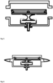
- Fig. 1 is used to produce an outer surface building element with a cast material base body, at least one fluid heat exchanger and a photovoltaic arrangement, the cast material base body being formed from concrete or mortar, which comprises at least one fluid heat exchanger and a fluid guide cast into the cast material base body and the fluid heat exchanger relative to the photovoltaic arrangement by a in the Cast material base body cast positioning means is fixed, a formwork 1 is used from an upper and a lower half of the formwork. The two formwork halves are each viewed from the side without the concrete filler neck 1 (upper part of Fig. 1 ), in the top view into the formwork (middle part of Fig. 1 ) and in section through the formwork (lower part of Fig. 1 ) shown.
- fluid connections 4 lead from the heat exchanger 3 through respective openings 5 in the formwork, which are formed as a hydraulic screw connection 5, with a clamping sleeve 6 being used for bracing or fixing on the lower half of the formwork and thus also fixing the positioning device relative to the formwork can be when this is in turn attached to the heat exchanger 3, as will be seen.
- the exits for the electrical connections of the PV laminate are not shown.
- Fig. 2 now shows how the PV laminate 2 is connected to the heat exchanger 3, which is connected to the lower formwork at its connections 4 - as described - via the hydraulic screw connection 5 and the clamping sleeve 6, and that is sufficiently tight to also hold it To fix the inflow of the casting material to the formwork.
- this fixed i.e. sufficiently immovable connection can be detached so that the formwork can be removed and reused after the cast material has hardened.
- fixed does not have the meaning of insoluble.
- the heat exchanger now has on its top side, i.e. on the side facing the PV laminate 2, receiving bearings for springs 7, with which the PV laminate can be pressed against the upper half of the formwork, which at the same time positions the photovoltaic arrangement relative to the fluid heat exchanger is fixed by a positioning means to be cast into the cast material base body.
- the positioning means and thus also the body 8 can be easily adapted to the geometry of the exterior building element to be produced in such a way that all edges of the PV laminate are stiffened all around, as shown in Fig. 2 with the three rods arranged on the long sides of the PV laminate.
- the stiffening can preferably be achieved by body 8, since a supporting substructure is formed from thin rods fixed together, which allows easy adaptation to different geometries and requires little material.
- the positioning means described here not only enables industrial production, but also ensures that the PV laminate attached to the positioning means is pressed onto the top-side formwork - and thus fixed relative to the heat exchanger - so that the PV laminate does not come off even when the formwork is being filled liquid high-performance fine-grain concrete will run behind it.
- the positioning means is also a pressing means for pressing the PV laminate against the formwork during casting.
- the positioning means shown and its fixation on the heat exchanger also allows the process of merging the positioning means first with the lower and then with the upper half of the formwork to be automated.
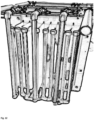
- the arrangement can be used, for example, but not only, to produce a roof tile as an exemplary exterior building element. It should be noted that the elements can be assembled before casting, as shown in the Figures 3 to 6 visible; the expert will understand that the steps there can be easily automated.
- the PV laminate is first prepared - not shown.
- an adhesive bridge is applied to the back of the laminate using a suitable adhesive in the form of sanding with coarse sand sieved grains of sand applied. Once the bonding bridge and coating has hardened, the laminate can be inserted and installed directly into the formwork with associated positioning.
- Fig. 3 the unit is formed from fluid heat exchanger 4, spring elements 7, prefabricated body 8 and photovoltaic laminate 2, which in Fig. 3 is shown. It will be apparent to those skilled in the art that when the formwork half is brought together, the PV laminates are pressed reliably and tightly against the formwork surface by means of the stiffening support structure 8, which avoids the formation of a cavity. It can also be seen that, in order to ensure the contact pressure, fixing points for coupling the positioning means are provided on the heat exchanger, see reference number 3a, where one end of the clamping springs is fixed. The other end is attached to brackets to be arranged on the underside of the support structure of the positioning device (not shown in detail in the figure).
- Fig.6 shows the formwork with fluid heat exchanger and PV laminate prepared for casting, with a seal surrounding the edge of the formwork not being shown.
- the individual components of the positioning means are stiffened in such a way that the photovoltaic elements are held reproducibly in the mold and that, when the two formwork halves are brought together, in view of the fixation of the positioning means on the heat exchanger, complex bonding etc. is no longer necessary. This applies even to cases in which, unlike the exemplary embodiment shown, very long, continuous tubes would be used for the heat exchangers.
- the upper formwork can be removed directly, as the double-sided adhesive tapes previously used are no longer required. Further time-consuming post-processing of the roof-facing surfaces is no longer necessary.
- fixing points for coupling the positioning means are provided on the heat exchanger, see reference number 3a, where one end of the clamping springs is fixed, while in the special exemplary embodiment the other ends of the clamping springs are attached the brackets to be arranged on the underside of the support structure of the positioning device.
- the positioning means used according to the invention allows the exterior building elements according to the invention to be manufactured precisely and reproducibly. It is therefore possible and also preferred if the thickness of the enveloping base body mass at the thinnest point and/or in the average between the base body mass interface, in particular the internal interface and the interface side of the fluid guide, is preferably not more than 5 mm. In other words, a particularly thick design does not have to be guaranteed over a large area and throughout.
- a robotically controlled production system can be implemented that, in addition to the sub-components of concrete production, formwork preparation, filling of the self-compacting fine-grain concrete and demoulding after hardening, can be carried out in an automated system.
- the base body material thicknesses can also be kept comparatively low because industrial production lines are used for installation, which enable installation technologies that cannot be achieved by hand. As a result, the exterior building elements no longer have to be oversized.
- fine-grain concrete In order to produce roof tiles as exemplary exterior building elements using the shapes and positioning means shown, concrete or mortar is used according to the invention, in particular fine-grain concrete.
- fine-grain recipes that can be used for the cast material base body of an exterior building element according to the invention and include binders, additives, sand, flow agents, deaerators and pigments are explained below. It is disclosed which fine-grain recipes are readily suitable for components of the invention.
- cement qualities which are readily suitable for the purposes of the invention, is suggested as a binder: CEM II/B-M (T-LL) 52.5 N; CEM II/B-S 52.5 R; CEM II/A-M (S-LL) 52.5 R; CEM II/B-M (V-LL) 42.5 R; CEM II/A-LL 52.5 R; CEM II/B-M (S-LL) 52.5 N-AZ; CEM II/C-M (S-LL) 42.5 N-NA; CEM IV/A (P) 42.5 N; CEM I 52.5 R and CEM I 42.5 R.
- cement qualities mentioned are readily suitable for producing the desired structural elements, it will be understood that the different cement qualities will be preferred differently due to different properties.
- the use of CEM I 52.5 R or CEM I 42.5 R is viewed as disadvantageous because it results in a particularly high CO2 load. Due to the ecological assessment, cement qualities such as CEM II/AM (S-LL) 52.5 R and CEM II/A-LL 52.5 R are also viewed as less preferred; In contrast, cement qualities such as CEM II/BM (T-LL) 52.5 N are preferred; CEM II/BM (V-LL) 42.5 R and CEM II/BM (S-LL) 52.5 N-AZ.
- cement qualities CEM II/CM (S-LL) 42.5 N-NA and CEM IV/A (P) 42.5 N are currently particularly preferred, although very slow hardening is to be expected with the latter , which can be advantageous depending on the manufacturing process can prove to ensure longer processing times, or is viewed as disadvantageous because an otherwise faster manufacturing process takes longer.
- Celitement should be mentioned here as an example, which can also be used without any problems and can be rated as ecologically very good. Due to its white color, Celitement also offers a very good option for the concrete base body of the exterior building elements through the use of commercially available powdered concrete pigments or - better yet - through the use of liquid colors, such as those used to color cement-bound concrete products, which are increasingly used in industrial concrete production Find to be able to offer in any color in which today's known roof tile systems that are on the market are also offered, so that the solar hybrid exterior building elements according to the invention are not limited in color.
- concrete additives can be added in addition to the selected binder. These can have an advantageous effect on the processability from mixing to pumping to completely filling the formwork.
- hardened concrete properties can be optimized in a targeted manner, since when cement is used alone, the hardening concrete elements tend to crack as a result of the shrinkage deformation that occurs due to the known large amount of cement clinker added to high-performance fine-grain concrete.
- the cement content is reduced through the use of concrete additives, the concrete elements are subject to lower internal and constrained stresses and the risk of cracking decreases. This is particularly important where particularly long-lasting products are desired.
- reactive concrete additives are often used (e.g. the group of pozzolans), which not only allow to improve the ecological balance of the concrete elements, but also result in an improvement in the mechanical performance characteristics and durability thanks to their contribution to strength formation have.
- concrete additives include fly ash, oil shale burning, limestone powder, metakaolin and phonolite. These additives produce different, desired properties. Fly ash contributes to good processability, phonolite contributes to good reactivity and oil shale burnup and metakaolin result in both good reactivity and good processability.
- Concrete ventilators support the ventilation of the fresh mortar to be filled into the formwork by allowing the amount of air that is inevitably mixed into the fresh concrete or mortar during the mixing process to be ventilated again during subsequent compaction after it has been introduced into the formwork.
- self-compacting concrete is preferably used, which should vent completely as it flows into the formwork in order to avoid unwanted air pockets in the fine concrete matrix. Therefore, it is preferred to use additives for ventilation that are adapted to the recipe.
- a variety of commercially available defoamers are suitable; Just as examples, SikaControl - 300 per Fin, Optec 960 from Grace, Centrament Surface Pro for low-pore concrete in exposed concrete quality, ALPHALITH ® Porex FE (BV) and ALPHALITH ® Porex DF 50 (BV) are mentioned.
- PCE polycarboxylate ethers
- Sika Visco Flow product range such as Sika ViscoFlow-26, Sika ViscoFlow-28, Sika ViscoFlow-32, Sika ViscoFlow or from the ViscoCrete product range.
- Sands with small grain sizes are preferred as sand, i.e. especially those with grain sizes of 0/2 mm and 0/4 mm.
- Fine crushed sand such as crushed basalt or crushed limestone, each with a grain size of 0/2 mm, can also be advantageously used; 0/4mm.
- Denser aggregates, e.g. basalt, are advantageous, as they generally also have a higher thermal conductivity and can therefore better dissipate the heat absorbed from the sun or the environment on the outer surface of the building element to the integrated heat exchanger.
- the components mentioned can, for example, be used in the following proportions to produce a quantity of 100 exterior building elements: components a lot of until binder 70kg 150kg Additives 20kg 70kg sand 200kg 300kg Flow agent 3kg 10kg ventilator 2kg 6kg Pigment red 0kg 10kg Black pigment 0kg 35kg
- roof tiles were produced according to the invention for experimental purposes, which were intended to visually match roof tiles commercially available from Laumann.
- the components were used in the following quantities to produce 100 roof tiles: binder 120.00 kg Additives 40.00 kg sand 240.00 kg Flow agent 7.00kg ventilator 3.00kg Pigment red 5.00kg Black pigment 30.00 kg
- roof tiles according to the invention could be produced, which corresponded so closely to the commercially available roof tiles both in terms of their shape and color that, at the typical distance between an observer standing in front of a building and the roof, there was a difference between the roof tiles according to the invention elements and the commercially available elements showed no visual differences. This makes it possible to install roof tiles according to the invention together with conventional roof tiles without affecting the visual appearance of a roof.
- these recipes make it possible to greatly reduce the clinker content in the binders, so that the solar hybrid roof tiles based on the present composition represent an important step towards the climate neutrality sought by the EU Green Deal and meet the goals of resource conservation.
- the latent heat of the water in the storage tank can also be used in addition to the sensitive heat normally used in heating systems.
- an amount of heat of around 117 Wh is stored, cf. Fig. 8 .
- These high sensible heat contents of the water are used, for example, in high-temperature storage systems.
- such storage devices require particularly efficient insulation of the container wall in order to be able to retain the stored heat over a certain period of time without major losses.
- a latent heat of 93 can be achieved with the heat pump simply by using the release of latent heat associated with the phase change from liquid to solid Wh per liter of water that freezes is supplied to the room heat.
- the heat extraction forced by the heat pump to provide room heat causes the phase change below the freezing point, which lasts until all the water has been transferred from the liquid to the solid phase.
- the temperature of the water-ice mixture remains at the freezing point temperature. Once all of the water has been converted into the solid phase, the temperature of the ice decreases as more heat is removed from the ice storage.
- this system allows the melting heat required to melt the ice to be supplied to the ice storage.
- this task is taken on by the exterior building elements. Even during the heating season, outside temperatures are usually more than 5 °C in all normal climate zones in Germany. This is explained using current weather data in the winter of the priority year. According to the observations of the German Weather Service (DWD), winters in Germany are consistently too warm compared to the reference periods. For example, the area average in the winter period 2022/2023 in Germany was 2.9 degrees Celsius (°C), which is 2.7 degrees above the value of the internationally valid reference period 1961 to 1990. In comparison to the current and warmer comparison period 1991 to 2020 the positive deviation was 1.5 degrees.
- the exterior building elements can also be used in an excellent way for the regeneration of the ice storage by supplying the brine, i.e. the heat transfer medium between the ice storage, the heat pump and the exterior building elements, to the hybrid roof elements, which are dependent on each other the prevailing outside temperature as a result of the absorption of environmental heat. Accordingly, the heat transfer medium flowing through the outer surface building elements absorbs the heat, which is then fed to the ice storage.
- brine i.e. the heat transfer medium between the ice storage, the heat pump and the exterior building elements
- a value of 120 Kd can be calculated for the Stuttgart area according to the DWD data. If a heating limit temperature of 15°C is set as the temperature above which no heat supply is required, a degree day number of 1,980 Kd is calculated for the same location and the same year. From this it can be deduced that regeneration of the storage at 1,860 Kd (Kelvin days) can be used for heating purposes. If 1 liter of water (equivalent to 1 kg) is heated by 1 degree using the exterior building elements, approximately 1.17 Wh of solar heat or environmental heat must be absorbed and fed to the heat transfer fluid in order to provide the ice storage with the required heat of melting. Regardless of the solar radiation, which immediately causes the exterior building elements to warm up, 77.5 liters of water can be heated by 1 degree using pure environmental heat absorption during the heating period, which can be used to regenerate the ice storage and thus use latent heat.
- hybrid exterior building elements as metal coverings for roofs and to provide a metal sheet such as a copper panel with standing seams on those longitudinal edges that follow the roof slope on the roof.
- An example of such an exterior building element is in Fig. 13 shown.
- historical copper sheet roofs can also be recreated with such arrangements.
- This is a large-format exterior building element that is provided with printed glass with ceramic digital printing, whereby a special printing pattern with a non-repeating dot grid can be selected, with large-format PV modules inserted between the copper sheets being fixed purely mechanically.
- the thermally and electrically activated system levels are coupled.
Landscapes
- Engineering & Computer Science (AREA)
- Structural Engineering (AREA)
- Civil Engineering (AREA)
- Architecture (AREA)
- Sustainable Development (AREA)
- Life Sciences & Earth Sciences (AREA)
- Thermal Sciences (AREA)
- Chemical & Material Sciences (AREA)
- Combustion & Propulsion (AREA)
- Mechanical Engineering (AREA)
- General Engineering & Computer Science (AREA)
- Sustainable Energy (AREA)
- Physics & Mathematics (AREA)
- Ceramic Engineering (AREA)
- Finishing Walls (AREA)
- Roof Covering Using Slabs Or Stiff Sheets (AREA)
- Photovoltaic Devices (AREA)
- Building Environments (AREA)
Applications Claiming Priority (1)
| Application Number | Priority Date | Filing Date | Title |
|---|---|---|---|
| EP22020159 | 2022-04-08 |
Publications (2)
| Publication Number | Publication Date |
|---|---|
| EP4257889A2 true EP4257889A2 (fr) | 2023-10-11 |
| EP4257889A3 EP4257889A3 (fr) | 2024-01-24 |
Family
ID=81307238
Family Applications (1)
| Application Number | Title | Priority Date | Filing Date |
|---|---|---|---|
| EP23020168.3A Pending EP4257889A3 (fr) | 2022-04-08 | 2023-04-02 | Éléments de construction multifonctionnels de surface extérieure, leur fabrication et leur utilisation |
Country Status (1)
| Country | Link |
|---|---|
| EP (1) | EP4257889A3 (fr) |
Citations (7)
| Publication number | Priority date | Publication date | Assignee | Title |
|---|---|---|---|---|
| DE3314637A1 (de) | 1982-04-27 | 1983-11-17 | BM CHEMIE Kunststoff GmbH, 5678 Wermelskirchen | Dachstein |
| DE3404978A1 (de) | 1984-02-11 | 1985-03-07 | Lammers, Albert, 7886 Murg | Dachpfannen als solarkollektoren |
| WO2008020462A1 (fr) | 2006-08-16 | 2008-02-21 | Maurizio De Nardis | Tuile solaire produisant de l'eau chaude et de l'énergie électrique par énergie solaire et photovoltaïque |
| EP2149647A2 (fr) | 2008-07-29 | 2010-02-03 | Deutsch, Wolfgang | Tuile |
| EP2230362A2 (fr) | 2009-03-21 | 2010-09-22 | Ulf Peter Hadwiger | Elément de revêtement |
| EP2336448A2 (fr) | 2009-12-15 | 2011-06-22 | Deutsch, Sabine Mag. (FH) | Tuile de toit dotée d'un corps de support constitué d'au moins deux couches |
| WO2016038178A1 (fr) | 2014-09-12 | 2016-03-17 | Schott Ag | Rouleau de verre mince et son procédé de fabrication |
Family Cites Families (11)
| Publication number | Priority date | Publication date | Assignee | Title |
|---|---|---|---|---|
| DE3011840A1 (de) * | 1980-03-27 | 1981-10-08 | Stefan Nau Gmbh & Co, 7405 Dettenhausen | Heizungsanlage zum ausnutzen der umweltwaerme und dazugehoeriger erdwaermeabsorber |
| AT380948B (de) * | 1981-05-12 | 1986-07-25 | Arnold Hefter | Anlage zur waermegewinnung mittels sonnenkollektoren |
| DE10104297A1 (de) * | 2000-02-01 | 2001-08-02 | Sylvia Bold | Ziegelanordnung für ein Dach oder eine Außenwand eines Gebäudes |
| JP2002294935A (ja) * | 2001-03-27 | 2002-10-09 | Sekisui Chem Co Ltd | 太陽電池付き屋根材及び屋根葺き構造 |
| DE102004052447A1 (de) * | 2004-10-26 | 2006-04-27 | Alex Von Rohr | Energiespeicher, Wärmetauscheranordnung für einen Energiespeicher, Verfahren zum Betreiben eines Energiespeichers, Energiespeichersystem sowie Verfahren zum Betreiben eines Energiespeichersystems |
| IT1392931B1 (it) * | 2009-02-17 | 2012-04-02 | Gigi Molina Brevetti Plastici Spa | Moduli fotovoltaici e procedimento per la loro produzione |
| EP2491596A4 (fr) * | 2009-10-22 | 2015-12-09 | Renewable Resource Recovery Corp | Assemblage de paroi avec panneau photovoltaïque |
| DE102011001273A1 (de) * | 2011-03-15 | 2012-09-20 | Isocal Heizkühlsysteme Gmbh | Speichertank für ein Energiespeichersystem und Energiespeichersystem mit derartigen Speichertanks |
| DE102012008852A1 (de) * | 2012-05-07 | 2013-11-07 | Ecomol AG | Dachziegel und Anordnung aus Dachziegeln |
| DE102016112784A1 (de) * | 2016-07-12 | 2018-01-18 | Viessmann Werke Gmbh & Co Kg | Kollektorfeld, Energieversorgungssystem mit einem Kollektorfeld sowie Verfahren zum Betreiben eines Energieversorgungssystems |
| IT201600101227A1 (it) * | 2016-10-10 | 2018-04-10 | Univ Bologna Alma Mater Studiorum | Pannello termofotovoltaico e procedimento di realizzazione di un pannello termofotovoltaico |
-
2023
- 2023-04-02 EP EP23020168.3A patent/EP4257889A3/fr active Pending
Patent Citations (7)
| Publication number | Priority date | Publication date | Assignee | Title |
|---|---|---|---|---|
| DE3314637A1 (de) | 1982-04-27 | 1983-11-17 | BM CHEMIE Kunststoff GmbH, 5678 Wermelskirchen | Dachstein |
| DE3404978A1 (de) | 1984-02-11 | 1985-03-07 | Lammers, Albert, 7886 Murg | Dachpfannen als solarkollektoren |
| WO2008020462A1 (fr) | 2006-08-16 | 2008-02-21 | Maurizio De Nardis | Tuile solaire produisant de l'eau chaude et de l'énergie électrique par énergie solaire et photovoltaïque |
| EP2149647A2 (fr) | 2008-07-29 | 2010-02-03 | Deutsch, Wolfgang | Tuile |
| EP2230362A2 (fr) | 2009-03-21 | 2010-09-22 | Ulf Peter Hadwiger | Elément de revêtement |
| EP2336448A2 (fr) | 2009-12-15 | 2011-06-22 | Deutsch, Sabine Mag. (FH) | Tuile de toit dotée d'un corps de support constitué d'au moins deux couches |
| WO2016038178A1 (fr) | 2014-09-12 | 2016-03-17 | Schott Ag | Rouleau de verre mince et son procédé de fabrication |
Non-Patent Citations (1)
| Title |
|---|
| H. GARRECHT ET AL.: "Praxistest für die Denkmalpflege - Solardachsteine", SCHÜTZEN UND ERHALTEN - MIT SACHVERSTAND UND HANDWERKSKUNST, vol. 31, 2021 |
Also Published As
| Publication number | Publication date |
|---|---|
| EP4257889A3 (fr) | 2024-01-24 |
Similar Documents
| Publication | Publication Date | Title |
|---|---|---|
| EP2061091B1 (fr) | Plaque de toit ou de façade avec panneaux solaires | |
| EP0850388B1 (fr) | Installation de production d'energie pour batiments | |
| DE2811829A1 (de) | Dachbelag | |
| EP1907765A1 (fr) | Paroi de batiment a passages fluidiques en tant que barrieres d'energie | |
| DE212012000104U1 (de) | Modulare Vorrichtung zur Wärmeübertragung mit einer Flüssigkeit | |
| EP2738479A2 (fr) | Revêtement de sol à accumulation de chaleur et plaque d'accumulation correspondante | |
| CN207484846U (zh) | 一种模块化海草房屋面 | |
| EP4257889A2 (fr) | Éléments de construction multifonctionnels de surface extérieure, leur fabrication et leur utilisation | |
| CN104631650A (zh) | 一种设有保温层的网板外墙及施工方法 | |
| EP2362156A2 (fr) | Système d'isolation thermique composite | |
| DE102008033398A1 (de) | Fassadenelement zur Verkleidung von Gebäuden | |
| DE3017223A1 (de) | Klimaanlage fuer wohnhaeuser | |
| CN101787775B (zh) | 混凝土结构太阳能房顶 | |
| DE4110116C2 (de) | Energiespeichernde Wärmedämmplatte | |
| DE102010054394A1 (de) | Solarfassadenelement, Solarfassadensystem | |
| DE2932628A1 (de) | Klimatisierungseinrichtung fuer gebaeude | |
| WO1999042766A1 (fr) | Dispositif pour capter l'energie solaire sur des batiments | |
| DE102008027309A1 (de) | Solarkollektor | |
| DE202011104258U1 (de) | Bauelement sowie Energiegewinnungsanordnung | |
| DE2937071A1 (de) | Verfahren zur rueckgewinnung der transmissionswaermeverluste bei gebaeuden aller art, sowie konstruktionsvorschlaege fuer solche gebaeude | |
| CN219316257U (zh) | 一种装配式外墙保温装饰一体板 | |
| DE3227899A1 (de) | Bau- und/oder betriebsweise zur verbesserung der energienutzung | |
| CN209099576U (zh) | 轻钢结构装配建筑的墙面结构 | |
| CN101851991B (zh) | 陶瓷太阳能房顶热水容器 | |
| EP0976886A2 (fr) | Elément de construction pour revêtement de toiture et/ou de façade et son procédé de fabrication |
Legal Events
| Date | Code | Title | Description |
|---|---|---|---|
| PUAI | Public reference made under article 153(3) epc to a published international application that has entered the european phase |
Free format text: ORIGINAL CODE: 0009012 |
|
| STAA | Information on the status of an ep patent application or granted ep patent |
Free format text: STATUS: THE APPLICATION HAS BEEN PUBLISHED |
|
| AK | Designated contracting states |
Kind code of ref document: A2 Designated state(s): AL AT BE BG CH CY CZ DE DK EE ES FI FR GB GR HR HU IE IS IT LI LT LU LV MC ME MK MT NL NO PL PT RO RS SE SI SK SM TR |
|
| PUAL | Search report despatched |
Free format text: ORIGINAL CODE: 0009013 |
|
| AK | Designated contracting states |
Kind code of ref document: A3 Designated state(s): AL AT BE BG CH CY CZ DE DK EE ES FI FR GB GR HR HU IE IS IT LI LT LU LV MC ME MK MT NL NO PL PT RO RS SE SI SK SM TR |
|
| RIC1 | Information provided on ipc code assigned before grant |
Ipc: H02S 20/25 20140101ALI20231219BHEP Ipc: F24S 70/16 20180101ALI20231219BHEP Ipc: F24S 20/66 20180101ALI20231219BHEP Ipc: F24S 20/69 20180101AFI20231219BHEP |
|
| STAA | Information on the status of an ep patent application or granted ep patent |
Free format text: STATUS: REQUEST FOR EXAMINATION WAS MADE |
|
| 17P | Request for examination filed |
Effective date: 20240718 |
|
| RBV | Designated contracting states (corrected) |
Designated state(s): AL AT BE BG CH CY CZ DE DK EE ES FI FR GB GR HR HU IE IS IT LI LT LU LV MC ME MK MT NL NO PL PT RO RS SE SI SK SM TR |