EP2149682A1 - Condensateur pour centrale à cycle combiné - Google Patents
Condensateur pour centrale à cycle combiné Download PDFInfo
- Publication number
- EP2149682A1 EP2149682A1 EP09165813A EP09165813A EP2149682A1 EP 2149682 A1 EP2149682 A1 EP 2149682A1 EP 09165813 A EP09165813 A EP 09165813A EP 09165813 A EP09165813 A EP 09165813A EP 2149682 A1 EP2149682 A1 EP 2149682A1
- Authority
- EP
- European Patent Office
- Prior art keywords
- steam
- condenser
- heat pipes
- heat
- passing
- Prior art date
- Legal status (The legal status is an assumption and is not a legal conclusion. Google has not performed a legal analysis and makes no representation as to the accuracy of the status listed.)
- Withdrawn
Links
- XLYOFNOQVPJJNP-UHFFFAOYSA-N water Substances O XLYOFNOQVPJJNP-UHFFFAOYSA-N 0.000 claims abstract description 23
- 238000000034 method Methods 0.000 claims description 9
- 239000002826 coolant Substances 0.000 claims description 4
- 238000011084 recovery Methods 0.000 claims description 4
- 239000011248 coating agent Substances 0.000 claims description 2
- 238000000576 coating method Methods 0.000 claims description 2
- 239000007791 liquid phase Substances 0.000 claims description 2
- 239000012808 vapor phase Substances 0.000 claims 1
- 239000007789 gas Substances 0.000 description 16
- 239000012530 fluid Substances 0.000 description 8
- 238000001816 cooling Methods 0.000 description 3
- 239000000463 material Substances 0.000 description 3
- CSCPPACGZOOCGX-UHFFFAOYSA-N Acetone Chemical compound CC(C)=O CSCPPACGZOOCGX-UHFFFAOYSA-N 0.000 description 2
- LFQSCWFLJHTTHZ-UHFFFAOYSA-N Ethanol Chemical compound CCO LFQSCWFLJHTTHZ-UHFFFAOYSA-N 0.000 description 2
- RYGMFSIKBFXOCR-UHFFFAOYSA-N Copper Chemical compound [Cu] RYGMFSIKBFXOCR-UHFFFAOYSA-N 0.000 description 1
- DGAQECJNVWCQMB-PUAWFVPOSA-M Ilexoside XXIX Chemical compound C[C@@H]1CC[C@@]2(CC[C@@]3(C(=CC[C@H]4[C@]3(CC[C@@H]5[C@@]4(CC[C@@H](C5(C)C)OS(=O)(=O)[O-])C)C)[C@@H]2[C@]1(C)O)C)C(=O)O[C@H]6[C@@H]([C@H]([C@@H]([C@H](O6)CO)O)O)O.[Na+] DGAQECJNVWCQMB-PUAWFVPOSA-M 0.000 description 1
- XAGFODPZIPBFFR-UHFFFAOYSA-N aluminium Chemical compound [Al] XAGFODPZIPBFFR-UHFFFAOYSA-N 0.000 description 1
- 229910052782 aluminium Inorganic materials 0.000 description 1
- -1 but not limited to Substances 0.000 description 1
- 229910052802 copper Inorganic materials 0.000 description 1
- 239000010949 copper Substances 0.000 description 1
- 238000001704 evaporation Methods 0.000 description 1
- 239000000446 fuel Substances 0.000 description 1
- 239000007788 liquid Substances 0.000 description 1
- QSHDDOUJBYECFT-UHFFFAOYSA-N mercury Chemical compound [Hg] QSHDDOUJBYECFT-UHFFFAOYSA-N 0.000 description 1
- 229910052753 mercury Inorganic materials 0.000 description 1
- 239000012071 phase Substances 0.000 description 1
- 229910052708 sodium Inorganic materials 0.000 description 1
- 239000011734 sodium Substances 0.000 description 1
- 229910001220 stainless steel Inorganic materials 0.000 description 1
- 239000010935 stainless steel Substances 0.000 description 1
Images

Classifications
-
- F—MECHANICAL ENGINEERING; LIGHTING; HEATING; WEAPONS; BLASTING
- F01—MACHINES OR ENGINES IN GENERAL; ENGINE PLANTS IN GENERAL; STEAM ENGINES
- F01K—STEAM ENGINE PLANTS; STEAM ACCUMULATORS; ENGINE PLANTS NOT OTHERWISE PROVIDED FOR; ENGINES USING SPECIAL WORKING FLUIDS OR CYCLES
- F01K9/00—Plants characterised by condensers arranged or modified to co-operate with the engines
-
- F—MECHANICAL ENGINEERING; LIGHTING; HEATING; WEAPONS; BLASTING
- F01—MACHINES OR ENGINES IN GENERAL; ENGINE PLANTS IN GENERAL; STEAM ENGINES
- F01K—STEAM ENGINE PLANTS; STEAM ACCUMULATORS; ENGINE PLANTS NOT OTHERWISE PROVIDED FOR; ENGINES USING SPECIAL WORKING FLUIDS OR CYCLES
- F01K11/00—Plants characterised by the engines being structurally combined with boilers or condensers
- F01K11/02—Plants characterised by the engines being structurally combined with boilers or condensers the engines being turbines
-
- F—MECHANICAL ENGINEERING; LIGHTING; HEATING; WEAPONS; BLASTING
- F01—MACHINES OR ENGINES IN GENERAL; ENGINE PLANTS IN GENERAL; STEAM ENGINES
- F01K—STEAM ENGINE PLANTS; STEAM ACCUMULATORS; ENGINE PLANTS NOT OTHERWISE PROVIDED FOR; ENGINES USING SPECIAL WORKING FLUIDS OR CYCLES
- F01K23/00—Plants characterised by more than one engine delivering power external to the plant, the engines being driven by different fluids
- F01K23/02—Plants characterised by more than one engine delivering power external to the plant, the engines being driven by different fluids the engine cycles being thermally coupled
- F01K23/06—Plants characterised by more than one engine delivering power external to the plant, the engines being driven by different fluids the engine cycles being thermally coupled combustion heat from one cycle heating the fluid in another cycle
- F01K23/10—Plants characterised by more than one engine delivering power external to the plant, the engines being driven by different fluids the engine cycles being thermally coupled combustion heat from one cycle heating the fluid in another cycle with exhaust fluid of one cycle heating the fluid in another cycle
- F01K23/106—Plants characterised by more than one engine delivering power external to the plant, the engines being driven by different fluids the engine cycles being thermally coupled combustion heat from one cycle heating the fluid in another cycle with exhaust fluid of one cycle heating the fluid in another cycle with water evaporated or preheated at different pressures in exhaust boiler
-
- F—MECHANICAL ENGINEERING; LIGHTING; HEATING; WEAPONS; BLASTING
- F28—HEAT EXCHANGE IN GENERAL
- F28B—STEAM OR VAPOUR CONDENSERS
- F28B1/00—Condensers in which the steam or vapour is separate from the cooling medium by walls, e.g. surface condenser
-
- F—MECHANICAL ENGINEERING; LIGHTING; HEATING; WEAPONS; BLASTING
- F28—HEAT EXCHANGE IN GENERAL
- F28D—HEAT-EXCHANGE APPARATUS, NOT PROVIDED FOR IN ANOTHER SUBCLASS, IN WHICH THE HEAT-EXCHANGE MEDIA DO NOT COME INTO DIRECT CONTACT
- F28D15/00—Heat-exchange apparatus with the intermediate heat-transfer medium in closed tubes passing into or through the conduit walls ; Heat-exchange apparatus employing intermediate heat-transfer medium or bodies
- F28D15/02—Heat-exchange apparatus with the intermediate heat-transfer medium in closed tubes passing into or through the conduit walls ; Heat-exchange apparatus employing intermediate heat-transfer medium or bodies in which the medium condenses and evaporates, e.g. heat pipes
-
- Y—GENERAL TAGGING OF NEW TECHNOLOGICAL DEVELOPMENTS; GENERAL TAGGING OF CROSS-SECTIONAL TECHNOLOGIES SPANNING OVER SEVERAL SECTIONS OF THE IPC; TECHNICAL SUBJECTS COVERED BY FORMER USPC CROSS-REFERENCE ART COLLECTIONS [XRACs] AND DIGESTS
- Y02—TECHNOLOGIES OR APPLICATIONS FOR MITIGATION OR ADAPTATION AGAINST CLIMATE CHANGE
- Y02E—REDUCTION OF GREENHOUSE GAS [GHG] EMISSIONS, RELATED TO ENERGY GENERATION, TRANSMISSION OR DISTRIBUTION
- Y02E20/00—Combustion technologies with mitigation potential
- Y02E20/16—Combined cycle power plant [CCPP], or combined cycle gas turbine [CCGT]
Definitions
- Exemplary embodiments of the present invention relate to the art of combined cycle power plants and, more particularly, to a condenser for a steam turbine portion of a combined cycle power plant.
- the gas turbine system includes a compressor coupled to a gas turbine.
- the steam turbine system includes a high pressure turbine (HP) portion operatively coupled to an intermediate pressure (IP) turbine portion that, in turn is coupled to low pressure (LP) turbine.
- HP high pressure turbine
- IP intermediate pressure
- LP low pressure
- the LP turbine is employed to drive, for example, a generator.
- exhaust gas from the steam turbine typically in the form of steam, is passed to a cooling system, onto a bottoming cycle and back to a heat recovery steam generator to be reheated and passed back to the steam turbine.
- a large amount of latent heat must be removed from the exhaust gas in to condense the steam back to water.
- Conventional cooling systems employ water to remove the latent heat from the exhaust/steam through a water-to-steam heat exchanger. Once condensed, a large cooling tower or a large water reservoir is required to cool/store the water. In places that lack water, a steam-to-air heat exchanger is used. Steam-to-air heat exchangers are less efficient that water-to-steam heat exchangers and require a large footprint.
- a combined cycle power plant in accordance with one exemplary embodiment of the invention, includes a steam turbine section having an inlet section and an outlet section.
- the steam turbine section passes steam from the inlet section toward the outlet section.
- the combined cycle power plant also includes a condenser fluidly connected to the outlet section of the steam turbine section.
- the condenser includes a plurality of heat pipes configured to extract latent heat from steam passing from the steam turbine section to form condensed water.
- a method of extracting latent heat from a steam flow passing from a steam turbine section includes passing the steam flow from the steam turbine section, guiding the steam flow to a condenser having a plurality of heat pipes, and passing the steam flow over the plurality of heat pipes.
- the heat pipes absorbing latent heat from the steam flow to form condensed water.
- a condenser fluidly connected to a steam turbine section includes a plurality of heat pipes configured to extract latent heat from steam passing from the steam turbine section to form condensed water.
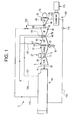
- FIG. 1 is a schematic view of a combined cycle power plant including a condenser constructed in accordance with exemplary embodiments of the invention.
- FIG. 2 is a partially cut-away right perspective view of a condenser constructed in accordance with exemplary embodiments of the invention.
- Power plant 2 includes a gas turbomachine system 4 operatively connected to steam turbomachine system 6.
- gas turbomachine system 4 includes a turbine 9 having an inlet portion 12 and an outlet portion 14.
- Turbine 9 is operatively connected to a compressor 17 via a shaft 19.
- Compressor 17 includes an inlet portion 22 and an outlet portion 24.
- Gas turbomachine system 4 further includes a combustor 27. With this arrangement, inlet air 30 passing into inlet portion 22 of compressor 17 is compressed, mixed with fuel from combustor 27 and ignited to form a high pressure, high temperate gas stream. The high temperature, high pressure gas stream is passed to turbine 9.
- Turbine 9 converts the high temperature, high pressure gas stream to rotational energy to produce work.
- the high temperature gases pass from outlet portion 14 of turbine 9 in the form of exhaust gases at a first temperature.
- steam turbomachine system 6 includes a high pressure (HP) turbine section 40 operatively coupled to compressor 17 via a shaft 42.
- HP turbine section 40 includes an inlet or high pressure stage section 45 and an outlet or low pressure stage section 47.
- HP turbine section 40 is also operatively coupled to an intermediate pressure (IP) turbine section 50 via a shaft 54.
- IP turbine section 50 includes an inlet section 56 and an outlet section 58. Steam at outlet section 58 is at a lower pressure than steam at inlet section 56.
- IP turbine section 50 is also operatively connected to a low pressure (LP) turbine section 64 via a shaft 66.
- LP low pressure
- LP turbine section 64 operates at a pressure of between approximately 60 psi -70 psi. Of course operating pressures both above 70 psi and below 60 psi could also employed. In any event, LP turbine section 64 includes an inlet section 68 and an outlet section 70, with steam at outlet section 70 being at a lower pressure at inlet section 68. LP turbine section 64 is operatively coupled to a generator 75 via a shaft 78. Steam turbomachine system 6 utilizes steam as a working fluid to drive generator 75. As will be discussed more fully below, power plant 2 is coupled to a heat recovery steam generator 90 that receives water from a condenser 100.
- condenser 100 is fluidly connected to LP turbine section 64 via conduit 105 and to HRSG 90 via a conduit 110. Water is pumped via a water pump 112 from condenser 100 to HRSG 90. HRSG 90 heats water obtained from condenser 100 to form steam at various pressures. The steam is delivered back to steam turbomachine system 6 via steam conduits indicated at 119-123.
- condenser 100 includes a main body 124 that defines a vessel having an inlet 125, an outlet 126 and an interior chamber 128.
- condenser 100 includes a plurality of heat pipes, indicated generally at 146, that are configured to absorb latent heat from a steam passing from LP turbine section 64.
- heat pipes should be construed to mean sealed pipes or tubes made of a material with having a high thermal conductivity such as, but not limited to, copper, stainless steel and/or aluminum.
- a vacuum pump is used to exclude all fluids (both gases and liquids) from an interior of the seal pipes after which the pipes are filled with a fraction of a percent by volume of a working fluid or coolant such as, but not limited to, water, ethanol, acetone, sodium or mercury.
- the partial vacuum is near to or below the vapor pressure of the working fluid such that, some of the fluid will be in a liquid phase and some will be in a gas phase.
- a wick (not shown) capable of absorbing fluid is located within the sealed pipes. The thermal energy is transferred to the heat pipe by evaporating fluid in the wick.
- Other examples of heat pipes include sealed pipes having no internal working fluid. Instead, such heat pipes include "Qu-materials" (not separately labeled) having a very high thermal conductivity. The"Qu-material” is typically in the form of a coating provided on internal or interior surfaces (not separately labeled) of the heat pipes.
- Each of the plurality of heat pipes 146 includes an external surface (not separately labeled), a first end portion 160 that extends through interior chamber 128, leading to a second end portion 161, arranged outside of the vessel, through an intermediate or heat exchange zone 163.
- Heat exchange zone 163 actually includes a first heat exchange portion 167, e.g., the portion of each of the plurality of heat pipes 146 located within interior chamber 128, and a second heat exchange portion 168, e.g., the portion of each of the plurality of heat pipes 146 located outside of interior chamber 128.
- second heat exchange portion 168 is arranged in a heat exchanger 170 positioned adjacent a pair of fans 174 and 175.
- a condenser constructed in accordance with exemplary embodiments of the invention would be simple to build and be easy to maintain and provide enhanced heat removal efficiency. Moreover, the condenser in accordance with the exemplary embodiment would not require water as a coolant or any associated water handling/storage equipment. Finally, the condenser in accordance with exemplary embodiments of the invention can be constructed on a relatively small footprint.
Landscapes
- Engineering & Computer Science (AREA)
- Mechanical Engineering (AREA)
- General Engineering & Computer Science (AREA)
- Chemical & Material Sciences (AREA)
- Combustion & Propulsion (AREA)
- Life Sciences & Earth Sciences (AREA)
- Sustainable Development (AREA)
- Physics & Mathematics (AREA)
- Thermal Sciences (AREA)
- Engine Equipment That Uses Special Cycles (AREA)
Applications Claiming Priority (1)
| Application Number | Priority Date | Filing Date | Title |
|---|---|---|---|
| US12/181,741 US20100024424A1 (en) | 2008-07-29 | 2008-07-29 | Condenser for a combined cycle power plant |
Publications (1)
| Publication Number | Publication Date |
|---|---|
| EP2149682A1 true EP2149682A1 (fr) | 2010-02-03 |
Family
ID=41278779
Family Applications (1)
| Application Number | Title | Priority Date | Filing Date |
|---|---|---|---|
| EP09165813A Withdrawn EP2149682A1 (fr) | 2008-07-29 | 2009-07-17 | Condensateur pour centrale à cycle combiné |
Country Status (4)
| Country | Link |
|---|---|
| US (1) | US20100024424A1 (fr) |
| EP (1) | EP2149682A1 (fr) |
| JP (1) | JP2010031863A (fr) |
| CN (1) | CN101660432A (fr) |
Citations (4)
| Publication number | Priority date | Publication date | Assignee | Title |
|---|---|---|---|---|
| US4033406A (en) * | 1974-09-03 | 1977-07-05 | Hughes Aircraft Company | Heat exchanger utilizing heat pipes |
| GB2099126A (en) * | 1981-04-27 | 1982-12-01 | Foster Wheeler Energy Corp | Steam condenser |
| EP0794401A2 (fr) * | 1996-03-06 | 1997-09-10 | Hudson Products Corporation | Condenseur de vapeur |
| US6241009B1 (en) * | 2000-02-07 | 2001-06-05 | Hudson Products Corporation | Integrated heat pipe vent condenser |
Family Cites Families (15)
| Publication number | Priority date | Publication date | Assignee | Title |
|---|---|---|---|---|
| US3517730A (en) * | 1967-03-15 | 1970-06-30 | Us Navy | Controllable heat pipe |
| US3722797A (en) * | 1970-11-04 | 1973-03-27 | Cci Aerospace Corp | Convergent divergent ejector exhaust nozzle |
| US4036290A (en) * | 1972-01-24 | 1977-07-19 | Kelly Donald A | Helical expansion condenser |
| US3852805A (en) * | 1973-06-18 | 1974-12-03 | Gen Electric | Heat-pipe cooled power semiconductor device assembly having integral semiconductor device evaporating surface unit |
| US4149588A (en) * | 1976-03-15 | 1979-04-17 | Mcdonnell Douglas Corporation | Dry cooling system |
| US4226282A (en) * | 1978-08-30 | 1980-10-07 | Foster Wheeler Energy Corporation | Heat exchange apparatus utilizing thermal siphon pipes |
| US4932204A (en) * | 1989-04-03 | 1990-06-12 | Westinghouse Electric Corp. | Efficiency combined cycle power plant |
| US5738024A (en) * | 1996-04-19 | 1998-04-14 | Winegar; Phillip | Catalytic reduction apparatus for NOX reduction |
| BR9713274A (pt) * | 1996-10-25 | 2000-03-21 | Yuzhi Qu | Meio de transferência de calor supercondutor |
| JPH1193694A (ja) * | 1997-09-18 | 1999-04-06 | Toshiba Corp | ガスタービンプラント |
| US7069716B1 (en) * | 2002-04-24 | 2006-07-04 | Express Integrated Technologies Llc | Cooling air distribution apparatus |
| JP2006284144A (ja) * | 2005-04-04 | 2006-10-19 | Denso Corp | 排熱回収装置 |
| US20070017207A1 (en) * | 2005-07-25 | 2007-01-25 | General Electric Company | Combined Cycle Power Plant |
| US20070234704A1 (en) * | 2005-09-01 | 2007-10-11 | General Electric Company | Methods and apparatus for operating gas turbine engines |
| US7382047B2 (en) * | 2005-12-27 | 2008-06-03 | Fu Zhun Precision Industry (Shen Zhen) Co., Ltd. | Heat dissipation device |
-
2008
- 2008-07-29 US US12/181,741 patent/US20100024424A1/en not_active Abandoned
-
2009
- 2009-07-17 EP EP09165813A patent/EP2149682A1/fr not_active Withdrawn
- 2009-07-23 JP JP2009171693A patent/JP2010031863A/ja not_active Withdrawn
- 2009-07-29 CN CN200910165351.7A patent/CN101660432A/zh active Pending
Patent Citations (4)
| Publication number | Priority date | Publication date | Assignee | Title |
|---|---|---|---|---|
| US4033406A (en) * | 1974-09-03 | 1977-07-05 | Hughes Aircraft Company | Heat exchanger utilizing heat pipes |
| GB2099126A (en) * | 1981-04-27 | 1982-12-01 | Foster Wheeler Energy Corp | Steam condenser |
| EP0794401A2 (fr) * | 1996-03-06 | 1997-09-10 | Hudson Products Corporation | Condenseur de vapeur |
| US6241009B1 (en) * | 2000-02-07 | 2001-06-05 | Hudson Products Corporation | Integrated heat pipe vent condenser |
Also Published As
| Publication number | Publication date |
|---|---|
| US20100024424A1 (en) | 2010-02-04 |
| CN101660432A (zh) | 2010-03-03 |
| JP2010031863A (ja) | 2010-02-12 |
Similar Documents
| Publication | Publication Date | Title |
|---|---|---|
| US8359824B2 (en) | Heat recovery steam generator for a combined cycle power plant | |
| CN102032070B (zh) | 双再热兰金循环系统及其方法 | |
| US8418467B2 (en) | System including feedwater heater for extracting heat from low pressure steam turbine | |
| US8157512B2 (en) | Heat pipe intercooler for a turbomachine | |
| KR101536988B1 (ko) | 초임계 열 회수 증기 발생기 재가열기 및 초임계 증발기 장치 | |
| US7600382B2 (en) | Turbine engine with interstage heat transfer | |
| RU2613100C2 (ru) | Газовая турбина (варианты) и способ эксплуатации газовой турбины | |
| US8037703B2 (en) | Heat recovery system for a turbomachine and method of operating a heat recovery steam system for a turbomachine | |
| CN101660451A (zh) | 用于燃气涡轮机入口的热管理的系统和方法 | |
| US20140331671A1 (en) | Water/steam cycle and method for operating the same | |
| JP4972708B2 (ja) | 蒸気を利用するプラント及びそのプラントの運転方法並びに蒸気供給装置及び蒸気供給方法 | |
| JP2011202657A (ja) | チラー復水系 | |
| US20100043442A1 (en) | Dimpled serrated fintube structure | |
| CN115199365A (zh) | 具有串联热交换器的联合循环发电厂 | |
| US20100024424A1 (en) | Condenser for a combined cycle power plant | |
| CN101881189A (zh) | 蒸汽涡轮动力系统及其组装方法 | |
| JP7833267B2 (ja) | 複合サイクル発電プラント用のグランド蒸気復水器およびその運転方法 | |
| RU2449134C2 (ru) | Паротурбинная мультитеплотрубная установка | |
| RU2686541C1 (ru) | Парогазовая установка | |
| US12116907B1 (en) | Steam discharge pipe blowback protection system | |
| KR101912014B1 (ko) | 누설증기를 이용한 터빈의 열교환 시스템 | |
| JP5262428B2 (ja) | ヒートポンプシステム | |
| KR101855001B1 (ko) | 터빈의 냉각 및 누설 차단 시스템 | |
| CN117287994A (zh) | 一种膨胀自凝式汽动系统 | |
| WO2017014027A1 (fr) | Système à cycle de rankine |
Legal Events
| Date | Code | Title | Description |
|---|---|---|---|
| PUAI | Public reference made under article 153(3) epc to a published international application that has entered the european phase |
Free format text: ORIGINAL CODE: 0009012 |
|
| AK | Designated contracting states |
Kind code of ref document: A1 Designated state(s): AT BE BG CH CY CZ DE DK EE ES FI FR GB GR HR HU IE IS IT LI LT LU LV MC MK MT NL NO PL PT RO SE SI SK SM TR |
|
| AX | Request for extension of the european patent |
Extension state: AL BA RS |
|
| 17P | Request for examination filed |
Effective date: 20100803 |
|
| 17Q | First examination report despatched |
Effective date: 20100831 |
|
| STAA | Information on the status of an ep patent application or granted ep patent |
Free format text: STATUS: THE APPLICATION IS DEEMED TO BE WITHDRAWN |
|
| 18D | Application deemed to be withdrawn |
Effective date: 20110311 |