EP2149694B1 - Vorrichtung zur Steuerung eines Verbrennungsmotors - Google Patents
Vorrichtung zur Steuerung eines Verbrennungsmotors Download PDFInfo
- Publication number
- EP2149694B1 EP2149694B1 EP09166873.1A EP09166873A EP2149694B1 EP 2149694 B1 EP2149694 B1 EP 2149694B1 EP 09166873 A EP09166873 A EP 09166873A EP 2149694 B1 EP2149694 B1 EP 2149694B1
- Authority
- EP
- European Patent Office
- Prior art keywords
- rotational
- internal combustion
- engine speed
- combustion engine
- engine
- Prior art date
- Legal status (The legal status is an assumption and is not a legal conclusion. Google has not performed a legal analysis and makes no representation as to the accuracy of the status listed.)
- Ceased
Links
- 238000002485 combustion reaction Methods 0.000 title claims description 135
- 230000002401 inhibitory effect Effects 0.000 claims description 193
- 238000000034 method Methods 0.000 claims description 94
- 230000008569 process Effects 0.000 claims description 91
- 238000013459 approach Methods 0.000 claims description 23
- 230000009977 dual effect Effects 0.000 claims description 22
- 230000005540 biological transmission Effects 0.000 claims description 13
- 230000008859 change Effects 0.000 claims description 13
- 230000004044 response Effects 0.000 claims description 8
- 230000009467 reduction Effects 0.000 claims description 3
- 239000000446 fuel Substances 0.000 description 24
- 238000002347 injection Methods 0.000 description 17
- 239000007924 injection Substances 0.000 description 17
- 230000005764 inhibitory process Effects 0.000 description 15
- 230000002829 reductive effect Effects 0.000 description 14
- 230000007423 decrease Effects 0.000 description 11
- 238000010586 diagram Methods 0.000 description 8
- 230000035939 shock Effects 0.000 description 8
- 230000000694 effects Effects 0.000 description 7
- 230000010355 oscillation Effects 0.000 description 7
- 230000003247 decreasing effect Effects 0.000 description 6
- 238000001514 detection method Methods 0.000 description 6
- 230000001133 acceleration Effects 0.000 description 4
- 230000001276 controlling effect Effects 0.000 description 3
- 230000000717 retained effect Effects 0.000 description 3
- 230000002265 prevention Effects 0.000 description 2
- 238000011144 upstream manufacturing Methods 0.000 description 2
- 239000003054 catalyst Substances 0.000 description 1
- 230000000052 comparative effect Effects 0.000 description 1
- 230000001934 delay Effects 0.000 description 1
- 230000000881 depressing effect Effects 0.000 description 1
- 238000001914 filtration Methods 0.000 description 1
- 239000012530 fluid Substances 0.000 description 1
- 230000001105 regulatory effect Effects 0.000 description 1
- 239000007858 starting material Substances 0.000 description 1
Images






Classifications
-
- F—MECHANICAL ENGINEERING; LIGHTING; HEATING; WEAPONS; BLASTING
- F02—COMBUSTION ENGINES; HOT-GAS OR COMBUSTION-PRODUCT ENGINE PLANTS
- F02D—CONTROLLING COMBUSTION ENGINES
- F02D41/00—Electrical control of supply of combustible mixture or its constituents
- F02D41/02—Circuit arrangements for generating control signals
- F02D41/021—Introducing corrections for particular conditions exterior to the engine
- F02D41/0215—Introducing corrections for particular conditions exterior to the engine in relation with elements of the transmission
-
- B—PERFORMING OPERATIONS; TRANSPORTING
- B60—VEHICLES IN GENERAL
- B60W—CONJOINT CONTROL OF VEHICLE SUB-UNITS OF DIFFERENT TYPE OR DIFFERENT FUNCTION; CONTROL SYSTEMS SPECIALLY ADAPTED FOR HYBRID VEHICLES; ROAD VEHICLE DRIVE CONTROL SYSTEMS FOR PURPOSES NOT RELATED TO THE CONTROL OF A PARTICULAR SUB-UNIT
- B60W10/00—Conjoint control of vehicle sub-units of different type or different function
- B60W10/04—Conjoint control of vehicle sub-units of different type or different function including control of propulsion units
- B60W10/06—Conjoint control of vehicle sub-units of different type or different function including control of propulsion units including control of combustion engines
-
- B—PERFORMING OPERATIONS; TRANSPORTING
- B60—VEHICLES IN GENERAL
- B60W—CONJOINT CONTROL OF VEHICLE SUB-UNITS OF DIFFERENT TYPE OR DIFFERENT FUNCTION; CONTROL SYSTEMS SPECIALLY ADAPTED FOR HYBRID VEHICLES; ROAD VEHICLE DRIVE CONTROL SYSTEMS FOR PURPOSES NOT RELATED TO THE CONTROL OF A PARTICULAR SUB-UNIT
- B60W10/00—Conjoint control of vehicle sub-units of different type or different function
- B60W10/10—Conjoint control of vehicle sub-units of different type or different function including control of change-speed gearings
- B60W10/11—Stepped gearings
-
- B—PERFORMING OPERATIONS; TRANSPORTING
- B60—VEHICLES IN GENERAL
- B60W—CONJOINT CONTROL OF VEHICLE SUB-UNITS OF DIFFERENT TYPE OR DIFFERENT FUNCTION; CONTROL SYSTEMS SPECIALLY ADAPTED FOR HYBRID VEHICLES; ROAD VEHICLE DRIVE CONTROL SYSTEMS FOR PURPOSES NOT RELATED TO THE CONTROL OF A PARTICULAR SUB-UNIT
- B60W30/00—Purposes of road vehicle drive control systems not related to the control of a particular sub-unit, e.g. of systems using conjoint control of vehicle sub-units
- B60W30/18—Propelling the vehicle
- B60W30/20—Reducing vibrations in the driveline
-
- B—PERFORMING OPERATIONS; TRANSPORTING
- B60—VEHICLES IN GENERAL
- B60W—CONJOINT CONTROL OF VEHICLE SUB-UNITS OF DIFFERENT TYPE OR DIFFERENT FUNCTION; CONTROL SYSTEMS SPECIALLY ADAPTED FOR HYBRID VEHICLES; ROAD VEHICLE DRIVE CONTROL SYSTEMS FOR PURPOSES NOT RELATED TO THE CONTROL OF A PARTICULAR SUB-UNIT
- B60W50/00—Details of control systems for road vehicle drive control not related to the control of a particular sub-unit, e.g. process diagnostic or vehicle driver interfaces
- B60W50/08—Interaction between the driver and the control system
- B60W50/14—Means for informing the driver, warning the driver or prompting a driver intervention
- B60W2050/146—Display means
-
- B—PERFORMING OPERATIONS; TRANSPORTING
- B60—VEHICLES IN GENERAL
- B60W—CONJOINT CONTROL OF VEHICLE SUB-UNITS OF DIFFERENT TYPE OR DIFFERENT FUNCTION; CONTROL SYSTEMS SPECIALLY ADAPTED FOR HYBRID VEHICLES; ROAD VEHICLE DRIVE CONTROL SYSTEMS FOR PURPOSES NOT RELATED TO THE CONTROL OF A PARTICULAR SUB-UNIT
- B60W2510/00—Input parameters relating to a particular sub-units
- B60W2510/06—Combustion engines, Gas turbines
- B60W2510/0614—Position of fuel or air injector
- B60W2510/0628—Inlet air flow rate
-
- B—PERFORMING OPERATIONS; TRANSPORTING
- B60—VEHICLES IN GENERAL
- B60W—CONJOINT CONTROL OF VEHICLE SUB-UNITS OF DIFFERENT TYPE OR DIFFERENT FUNCTION; CONTROL SYSTEMS SPECIALLY ADAPTED FOR HYBRID VEHICLES; ROAD VEHICLE DRIVE CONTROL SYSTEMS FOR PURPOSES NOT RELATED TO THE CONTROL OF A PARTICULAR SUB-UNIT
- B60W2520/00—Input parameters relating to overall vehicle dynamics
- B60W2520/10—Longitudinal speed
-
- B—PERFORMING OPERATIONS; TRANSPORTING
- B60—VEHICLES IN GENERAL
- B60W—CONJOINT CONTROL OF VEHICLE SUB-UNITS OF DIFFERENT TYPE OR DIFFERENT FUNCTION; CONTROL SYSTEMS SPECIALLY ADAPTED FOR HYBRID VEHICLES; ROAD VEHICLE DRIVE CONTROL SYSTEMS FOR PURPOSES NOT RELATED TO THE CONTROL OF A PARTICULAR SUB-UNIT
- B60W2540/00—Input parameters relating to occupants
- B60W2540/10—Accelerator pedal position
-
- B—PERFORMING OPERATIONS; TRANSPORTING
- B60—VEHICLES IN GENERAL
- B60W—CONJOINT CONTROL OF VEHICLE SUB-UNITS OF DIFFERENT TYPE OR DIFFERENT FUNCTION; CONTROL SYSTEMS SPECIALLY ADAPTED FOR HYBRID VEHICLES; ROAD VEHICLE DRIVE CONTROL SYSTEMS FOR PURPOSES NOT RELATED TO THE CONTROL OF A PARTICULAR SUB-UNIT
- B60W2540/00—Input parameters relating to occupants
- B60W2540/12—Brake pedal position
Definitions
- the present invention relates to a control device for an internal combustion engine which transmits output to a drive-train via a dual mass flywheel.
- a technique is known that a dual mass flywheel is used to inhibit torque fluctuation of an internal combustion engine from being transmitted to a drive-train (see, for example, Japanese Patent Application Publication No. 2005-54601 ( JP-A-2005-54601 ) and Japanese Patent Application Publication No. 2006-183484 ( JP-A-2006-183484 )).
- the dual mass flywheel includes two flywheels that are connected together by an elastic body such as a spring. Therefore, the dual mass flywheel has a resonance frequency. If resonance occurs, it causes a large oscillation amplitude between the two flywheels. This may result in a shock due to an impact with the spring.
- the resonance point is normally set at an engine speed range that is lower than the idling speed.
- the engine speed temporarily becomes lower than the idling speed depending on the operating state of the internal combustion engine. Therefore, only such a setting of the resonance point cannot sufficiently inhibit resonance of the dual mass flywheel.
- JP-A-2005-54601 on pages 5 to 9 and FIGs. 2 to 5
- fuel supply is stopped or reduced to control so that the engine speed of the internal combustion engine is retained out of the resonance rotational speed range.
- JP-A-2006-183484 on pages 3 to 5 and FIG. 2
- the maximum fuel injection amount at the engine speed that is lower than the idling speed is limited to not more than the maximum fuel injection amount at the idling speed.
- European Patent Application EP 2 031 223 discloses a controller for an internal combustion engine.
- the controller includes a rotation speed fluctuation detection means and an output fluctuation adjusted means.
- the rotation speed fluctuation detection means detects the level of fluctuation in a crankshaft rotation speed of the internal combustion engine.
- the output fluctuation adjustment means reduces or eliminates fluctuations in the output of the internal combustion engine when the level of fluctuation detected by the rotation speed fluctuation detection means becomes greater than a reference value.
- European Patent Application EP 2 071 163 discloses a control apparatus for an engine and a method for controlling an engine.
- Japanese Patent Application JP 59085443 discloses a device for reducing torque fluctuation at two-divided fly-wheels.
- UK Patent Application GB 2329427 discloses a controller for controlling vibration in an internal combustion engine when the engine passes through a low speed resonance range.
- Examples of the present invention control the resonance inhibiting process at an appropriate timing in contemplation of the approaching of the engine speed of the internal combustion engine to the resonance rotational speed.
- a first example provides a control device for an internal combustion engine that transmits output to a drive-train via a dual mass flywheel, the control device including: an engine rotational state detecting unit that detects a rotational state of the internal combustion engine; a rotational fluctuation inhibiting unit that executes a process of inhibiting rotational fluctuation for the internal combustion engine when a rotational state that is detected by the engine rotational state detecting unit satisfies a rotational fluctuation inhibiting condition; and a rotational fluctuation inhibiting condition adjusting unit that adjusts the rotational fluctuation inhibiting condition based on a operating state of the internal combustion engine.
- the rotational fluctuation inhibiting condition adjusting unit adjusts the rotational fluctuation inhibiting condition that is used in the rotational fluctuation inhibiting unit based on the operating state of the internal combustion engine.
- the adjustment allows the control device taking into consideration the approaching state of the engine speed of the internal combustion engine to the resonance rotational speed. Therefore, the resonance inhibiting process may be executed at an appropriate timing, thus allowing inhibition of strong resonance and an engine stall.
- the rotational fluctuation inhibiting condition adjusting unit adjusts the rotational fluctuation inhibiting condition so that the rotational fluctuation inhibiting condition is earlier satisfied when the rotational state that is detected by the engine rotational state detecting unit more easily approaches the resonance rotational speed of the dual mass flywheel.
- the rotational fluctuation inhibiting condition is adjusted, and thereby the rotational fluctuation inhibiting condition is earlier satisfied when the rotational state of the internal combustion engine more easily approaches the resonance rotational speed of the dual mass flywheel.
- the rotational fluctuation inhibiting condition is more slowly satisfied when the rotational state of the internal combustion engine less easily approaches the resonance rotational speed of the dual mass flywheel.
- the resonance inhibiting process can be executed at an appropriate timing, thus allowing inhibition of strong resonance and an engine stall.
- the internal combustion engine rotational state detecting unit may detect an average engine speed of the internal combustion engine as the rotational state.
- the rotational fluctuation inhibiting unit may set, as the rotational fluctuation inhibiting condition, a condition that an actual average engine speed of the internal combustion engine is lower than a reference value that is set for the average engine speed of the internal combustion engine.
- the rotational fluctuation inhibiting condition adjusting unit may adjust the reference value so that the rotational fluctuation inhibiting condition is earlier satisfied when the deceleration of the average engine speed of the internal combustion engine that is detected by the internal combustion engine rotational state detecting unit is larger.
- the rotational fluctuation inhibiting condition adjusting unit may increase the reference value to a larger value when the deceleration of the average engine speed of the internal combustion engine that is detected by the engine rotational state detecting unit is larger.
- the reference value is increased to a larger value when the deceleration of the average engine speed of the internal combustion engine is larger, as described above. This allows the rotational fluctuation inhibiting condition being early satisfied. Further, the reference value is reduced to a smaller value when the deceleration of the average engine speed of the internal combustion engine is smaller. This allows the rotational fluctuation inhibiting condition being slowly satisfied.
- the resonance inhibiting process can be executed at an appropriate timing, thus allowing inhibition of strong resonance and an engine stall.
- the engine rotational state detecting unit may detect rotational fluctuation of the internal combustion engine and the average engine speed of the internal combustion engine as the rotational state.
- the rotational fluctuation inhibiting unit may set, as the rotational fluctuation inhibiting condition, a condition that an actual engine speed fluctuation amount of the internal combustion engine is larger than a reference value that is set for the engine speed fluctuation amount of the internal combustion engine.
- the rotational fluctuation inhibiting condition adjusting unit may adjust the reference value so that the rotational fluctuation inhibiting condition is earlier satisfied when the deceleration of the average engine speed of the internal combustion engine that is detected by the internal combustion engine rotational state detecting unit is larger.
- the rotational state more rapidly approaches the resonance rotational speed and more rapidly approaches a state that the actual engine speed fluctuation amount of the internal combustion engine becomes larger than the reference value.
- the rotational fluctuation inhibiting condition is earlier satisfied when the deceleration of the average engine speed of the internal combustion engine is larger. Accordingly, the resonance inhibiting process is earlier started. This allows the control device to work before strong resonance actually occurs. Thereby, resonance can be inhibited. In other words, the rotational fluctuation inhibiting condition is more slowly satisfied when the deceleration of the average engine speed of the internal combustion engine is smaller. Therefore, the resonance inhibiting process is not executed unnecessarily early. Accordingly, the output of the internal combustion engine can be prevented from decreasing more than necessary, thus allowing prevention of an engine stall.
- the rotational fluctuation inhibiting condition adjusting unit may reduce the reference value to a smaller value when the deceleration of the average engine speed of the internal combustion engine that is detected by the engine rotational state detecting unit is larger.
- the reference value is reduced to a smaller value when the deceleration of the average engine speed of the internal combustion engine is larger, as described above. This allows the rotational fluctuation inhibiting condition being early satisfied.
- the reference value is increased to a larger value when the deceleration of the average engine speed of the internal combustion engine is smaller.
- the reference value is increased to a larger value as described above. This allows the rotational fluctuation inhibiting condition being slowly satisfied.
- the resonance inhibiting process can be executed at an appropriate timing, thus allowing inhibition of strong resonance and an engine stall.
- the rotational fluctuation inhibiting unit may set, as the rotational fluctuation inhibiting condition, a condition that an actual average engine speed of the internal combustion engine is lower than the reference value that is set for the average engine speed of the internal combustion engine and an actual engine speed fluctuation amount of the internal combustion engine is larger than the reference value set for the engine speed fluctuation amount of the internal combustion engine. Further, the rotational fluctuation inhibiting unit may execute the process of inhibiting rotational fluctuation for the internal combustion engine when the both conditions are satisfied.
- the rotational state more rapidly approaches a state that the actual average engine speed of the internal combustion engine becomes lower than the reference value, and more rapidly approaches a state that the actual engine speed fluctuation amount of the internal combustion engine becomes larger than the reference value.
- the two rotational fluctuation inhibiting conditions are earlier satisfied when the deceleration of the average engine speed of the internal combustion engine is larger. Accordingly, the resonance inhibiting process is early started. In other words, the two rotational fluctuation inhibiting conditions are more slowly satisfied when the deceleration of the average engine speed of the internal combustion engine is smaller, and thereby the resonance inhibiting process is slowly started.
- the internal combustion engine is for driving a vehicle.
- the engine rotational state detecting unit may detect vehicle deceleration as the rotational state of the internal combustion engine.
- the vehicle deceleration can be used as the rotational state of the internal combustion engine in the case that the internal combustion engine is for driving the vehicle. This also allows an execution of the resonance inhibiting process at an appropriate timing, thus allowing inhibition of strong resonance and an engine stall.
- control device may further include a drive-train output transmitting state detecting unit that detects an output transmitting state of the drive-train.
- the rotational fluctuation inhibiting condition adjusting unit may change the adjustment state of the rotational fluctuation inhibiting condition based on the output transmitting state that is detected by the drive-train output transmitting state detecting unit.
- the rotational fluctuation inhibiting condition adjusting unit changes the adjustment state of the rotational fluctuation inhibiting condition based on the output transmitting state that is detected by the drive-train output transmitting state detecting unit. This allows the control device handling the change in the resonance rotational speed. Accordingly, the rotational fluctuation inhibiting condition can be more highly accurately set.
- the rotational fluctuation inhibiting condition adjusting unit may change the adjustment state of the rotational fluctuation inhibiting condition based on resonance rotational speed of the dual mass flywheel that changes in response to the output transmitting state that is detected by the drive-train output transmitting state detecting unit.
- the adjustment state of the rotational fluctuation inhibiting condition is changed based on the resonance rotational speed of the dual mass flywheel that changes in response to the output transmitting state, thereby realizing more highly accurate setting of the rotational fluctuation inhibiting condition.
- the drive-train may include a transmission.
- the drive-train output transmitting state detecting unit may detect a gear position of the transmission as the output transmitting state of the drive-train.
- the gear position of the transmission can be used as the output transmitting state of the drive-train. Accordingly, the rotational fluctuation inhibiting condition can be highly accurately set based on the difference in the resonance rotational speed according to the gear positions.
- a second example provides a control device for an internal combustion engine that transmits output to a drive-train via a dual mass flywheel, the control device including: a drive-train output transmitting state detecting unit that detects an output transmitting state of the drive-train; an engine rotational state detecting unit that detects a rotational state of the internal combustion engine; a rotational fluctuation inhibiting unit that executes a process of inhibiting rotational fluctuation for the internal combustion engine when a rotational state that is detected by the engine rotational state detecting unit satisfies a rotational fluctuation inhibiting condition; and a rotational fluctuation inhibiting condition adjusting unit that adjusts the rotational fluctuation inhibiting condition based on an output transmitting state that is detected by the drive-train output transmitting state detecting unit.
- the rotational fluctuation inhibiting condition adjusting unit adjusts the rotational fluctuation inhibiting condition that is used in the rotational fluctuation inhibiting unit based on the output transmitting state from the internal combustion engine to the drive-train.
- the adjustment allows the control device accurately determining the approaching state of the average engine speed of the internal combustion engine to the resonance rotational speed. Therefore, the resonance inhibiting process can be executed at an appropriate timing, thus allowing inhibition of strong resonance and an engine stall.
- the drive-train may include a transmission.
- the drive-train output transmitting state detecting unit may detect the gear position of the transmission as the output transmitting state of the drive-train.
- the gear position of the transmission can be used as the output transmitting state of the drive-train. Accordingly, the rotational fluctuation inhibiting condition can be highly accurately set based on the difference in the resonance rotational speed according to the gear positions.
- the rotational fluctuation inhibiting condition adjusting unit may adjust the rotational fluctuation inhibiting condition so that the rotational fluctuation inhibiting condition is earlier satisfied when the output transmitting state that is detected by the drive-train output transmitting state detecting unit more easily approaches the resonance rotational speed of the dual mass flywheel.
- the rotational fluctuation inhibiting condition is adjusted so that the rotational fluctuation inhibiting condition is early satisfied when the output transmitting state more easily approaches the resonance rotational speed.
- the rotational fluctuation inhibiting condition is adjusted so that the rotational fluctuation inhibiting condition is more slowly satisfied when the output transmitting state less easily approaches the resonance rotational speed. Accordingly, the resonance inhibiting process can be executed at an appropriate timing, thus allowing inhibition of strong resonance and an engine stall.
- the rotational fluctuation inhibiting condition adjusting unit may adjust the rotational fluctuation inhibiting condition based on the resonance rotational speed of the dual mass flywheel that corresponds to the output transmitting state that is detected by the drive-train output transmitting state detecting unit.
- the rotational fluctuation inhibiting condition is adjusted based on the resonance rotational speed of the dual mass flywheel that corresponds to the output transmitting state. This allows more accurate determination about the state that strong resonance actually occurs and allows the control device working before strong resonance occurs.
- the engine rotational state detecting unit may detect an average engine speed of the internal combustion engine as the rotational state.
- the rotational fluctuation inhibiting unit may set, as the rotational fluctuation inhibiting condition, a condition that an actual average engine speed of the internal combustion engine is lower than a reference value that is set for the average engine speed of the internal combustion engine.
- the rotational fluctuation inhibiting condition adjusting unit may increase the reference value to a larger value when the resonance rotational speed that corresponds to the output transmitting state that is detected by the drive-train output transmitting state detecting unit is higher, and thereby adjust the rotational fluctuation inhibiting condition so that the condition is early satisfied.
- the reference value is increased to a larger value when the resonance rotational speed is higher, in other words, when the rotational state more easily approaches the resonance rotational speed. Accordingly, the rotational fluctuation inhibiting condition is early satisfied. Conversely, the reference value is reduced to a smaller value when the resonance rotational speed is lower, in other words, when the rotational speed less easily approaches the resonance rotational speed. Thereby, the rotational fluctuation inhibiting condition is slowly satisfied.
- the resonance inhibiting process can be executed at an appropriate timing, thus allowing inhibition of strong resonance and an engine stall.
- the engine rotational state detecting unit may detect rotational fluctuation of the internal combustion engine as the rotational state.
- the rotational fluctuation inhibiting unit may set, as the rotational fluctuation inhibiting condition, a condition that an actual engine speed fluctuation amount of the internal combustion engine is larger than a reference value that is set for the engine speed fluctuation amount of the internal combustion engine.
- the rotational fluctuation inhibiting condition adjusting unit may reduce the reference value to a smaller value when the resonance rotational speed that corresponds to the output transmitting state that is detected by the drive-train output transmitting state detecting unit is higher, and thereby may adjust the rotational fluctuation inhibiting condition so that the condition is early satisfied.
- the reference value is reduced to a smaller value when the resonance rotational speed is higher, in other words, when the rotational state more easily approaches the resonance rotational speed. Accordingly, the rotational fluctuation inhibiting condition is early satisfied. Conversely, the reference value is increased to a larger value when the resonance rotational speed is lower, in other words, when the rotational speed less easily approaches the resonance rotational speed. Thereby, the rotational fluctuation inhibiting condition is slowly satisfied.
- the resonance inhibiting process can be executed at an appropriate timing, thus allowing inhibition of strong resonance and an engine stall.
- the rotational fluctuation inhibiting unit may set, as the rotational fluctuation inhibiting condition, a condition that an actual average engine speed of the internal combustion engine is lower than the reference value that is set for the average engine speed of the internal combustion engine and an actual engine speed fluctuation amount of the internal combustion engine is larger than the reference value that is set for the engine speed fluctuation amount of the internal combustion engine. Further, the rotational fluctuation inhibiting unit may execute the process of inhibiting rotational fluctuation for the internal combustion engine when the conditions are both satisfied.
- the adjustment when the resonance rotational speed is higher, the adjustment is earlier made so that the actual average engine speed becomes lower than the reference value and the engine speed fluctuation amount of the internal combustion engine becomes larger than the reference value. Conversely, when the resonance rotational speed is lower, the adjustment is more slowly made so that the actual average engine speed becomes lower than the reference value and the engine speed fluctuation amount of the internal combustion engine becomes larger than the reference value.
- the rotational fluctuation inhibiting unit may execute either reduction of the output of the internal combustion engine or a change of the output fluctuation frequency of the internal combustion engine or both of those and thereby may execute a process of inhibiting rotational fluctuation for the internal combustion engine.
- either the reduction of the output of the internal combustion engine or the change of the output fluctuation frequency of the internal combustion engine is executed, or both of those are executed, thereby allowing inhibition of rotational fluctuation of the internal combustion engine.
- FIG. 1 is a block diagram showing a diesel engine (hereinafter referred to as "engine") 2 as an internal combustion engine for driving a vehicle to which an embodiment of the present invention is applied, a drive-train, and a control system thereof.
- the engine 2 is a inline four-cylinder engine.
- a fuel injection valve 4 for directly injecting fuel into a combustion chamber is disposed in each cylinder.
- the fuel injection valve 4 communicates with a common rail 6 that accumulates fuel at a predetermined pressure.
- the common rail 6 is supplied with pressurized fuel from a fuel pump that is rotated by the engine 2.
- a specified drive current is applied to the fuel injection valve 4, and thereby the fuel injection valve 4 is opened.
- pressurized fuel that is distributed from the common rail 6 to the fuel injection valve 4 of each cylinder is injected from the fuel injection valve 4 into the cylinder.
- An intake manifold 8 is connected to the engine 2. Each branch pipe of the intake manifold 8 communicates with the combustion chamber of each cylinder via an intake port. The intake manifold 8 is connected to an intake pipe 10. Intake air flows into the intake manifold 8 through the intake pipe 10.
- a diesel throttle valve (hereinafter referred to as "D-throttle") 12 for regulating the intake air amount is mounted on the intake pipe 10.
- An electric actuator 14 adjusts the opening of the D-throttle 12. Further, an inter-cooler, a compressor of a turbocharger, and an air cleaner are disposed upstream of the intake pipe 10.
- An exhaust gas recirculation passage (EGR passage) 16 opens at a portion of the intake pipe 10 downstream of the D-throttle 12. A part of exhaust gas that flows in the exhaust passage of the engine 2 is introduced into the EGR passage 16 at a portion upstream thereof. Thereby, exhaust gas is introduced into the intake pipe 10 as EGR gas via an EGR valve 18 for adjusting the flow rate.
- EGR passage exhaust gas recirculation passage
- a turbine of the turbocharger On the exhaust passage, a turbine of the turbocharger is rotated by fluid energy of exhaust gas.
- the exhaust gas that has rotated the turbine is purified by an exhaust purifying catalyst and thereafter discharged.
- the output of the engine 2 is transmitted toward a manual transmission (hereinafter abbreviated as "MT") 28 via a dual mass flywheel (hereinafter abbreviated as "DMF") 24 that includes a primary flywheel 20 and a secondary flywheel 22 and a clutch 26 that is provided on the secondary flywheel 22 side.
- the MT 28 is a transmission that has six forward speed and one rearward speed.
- the DMF 24 is constructed such that the primary flywheel 20 and the secondary flywheel 22 are connected together via a spring 24a.
- the primary flywheel 20 and the secondary flywheel 22 are connected together in a manner such that the respective rotational shafts 20a and 22a are capable of relative rotation with bearings 24b interposed therebetween.
- the output of the engine 2 is transmitted from a crankshaft 2a toward the MT 28 by the DMF 24. Output fluctuation of the engine 2 is absorbed and reduced by the spring 24a. Therefore, torsional oscillation of the drive-train can be inhibited in the normal operation. Further, generation of noise and oscillation due to the torsional oscillation can be reduced.
- An electronic control unit (ECU) 30 for controlling the engine operating state is provided for such an engine 2.
- the ECU 30 is a control circuit that controls the engine operating state according to the engine operating state and demands of a driver.
- the ECU 30 is mainly constructed with a microcomputer which includes CPU, ROM, RAM, and backup RAM.
- the ECU 30 receives various signals from a crankshaft rotational speed sensor 32 that detects the rotational speed of the crankshaft 2a, an opening sensor 34 that detects the opening of the D-throttle 12, and a shift sensor 36 that detects the gear position of the MT 28.
- the ECU 30 also receives signals from a vehicle speed sensor, an accelerator operation amount sensor, a brake switch, a clutch switch, an intake air amount sensor, a fuel pressure sensor, and other kinds of sensors and switches.
- the ECU 30 makes appropriate adjustments for the fuel injection amount, fuel injection timing, opening of the D-throttle 12, and opening of the EGR valve 18 according to detection data of the sensors and switches and each kind of control computation.
- Information about states of the vehicle and the engine 2 is provided to the driver according to need by LCDs and lamps on a display 38 that is disposed on a dashboard.
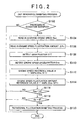
- a DMF resonance inhibiting process that is executed by the ECU 30 will be shown in a flowchart in FIG. 2 .
- the process is repeatedly executed by interruption at a constant time period. Steps in the flowchart corresponding to each process will be denoted as "S-(numeral)".
- the prerequisite condition is satisfied only if the following three conditions (1) to (3) are all satisfied.
- the clutch switch is turned off (the clutch 26 is connected).
- the starter is turned off.
- the brake switch is turned on (braking by depressing the brake pedal is being made).
- an average engine speed Nea (rpm) of the engine 2 is read (S104).
- the average engine speed Nea is an engine speed from which rotational fluctuation of engine 2 is removed and is a value that the ECU 30 separately and repeatedly calculates with the detection value of the crankshaft rotational speed sensor 32 by a filtering process such as a weighted mean process.
- an engine speed fluctuation amount ⁇ Ne (rpm) is read (S106).
- the engine speed fluctuation amount ⁇ Ne is a peak value in the absolute values of the differences between the average engine speed Nea and an instant engine speed Ne and is a value that the ECU 30 separately and repeatedly calculates.
- a gear position SFT of the MT 28 is detected based on the signal of the shift sensor 36 (S108).
- an engine speed deceleration Dne (rpm/s) is detected (S110).
- the engine speed deceleration Dne is a decrease in the averatge engine speed Nea per a unit time (here one second).
- an engine speed reference value A (a reference value that is set on the average engine speed of the internal combustion engine) is set according to an engine speed reference value setting map MAPa that is shown in FIG. 4 and based on the engine speed deceleration Dne and the gear position SFT (S112).
- the map MAPa indicates that if the gear position is fixed, when the engine speed deceleration Dne is larger, in other words, when the average engine speed Nea more rapidly decreases, a higher engine speed is set as the engine speed reference value A.
- upper and lower limits lower engine speed limit and upper engine speed limit in the drawing
- the reference value A converges into a certain engine speed.
- the engine speed reference value A converges into different lower engine speed limit for each of the gear positions SFT in the lower range of the engine speed deceleration Dne. In this case, the engine speed reference value A converges into a higher engine speed when the gear position SFT is set to a higher gear position. On the other hand, the engine speed reference value A converges into the same upper engine speed limit for all the gear positions in the higher range of the engine speed deceleration Dne.
- FIG. 5 is a graph that indicates the relationship between the average engine speed Nea and the engine speed fluctuation amount ⁇ Ne at a certain gear position (herein, the fourth gear position).
- each of engine speeds Ne1, Ne2, and Ne3 indicates the engine speed reference value A that is set on the map MAPa based on the engine speed deceleration Dne.
- the engine speed Ne1 corresponds to the engine speed reference value A in the higher range of the engine speed deceleration Dne.
- the engine speed Ne2 corresponds to the engine speed reference value A in the intermediate range of the engine speed deceleration Dne.
- the engine speed Ne3 corresponds to the engine speed reference value A in the lower range of the engine speed deceleration Dne.
- a range that such an engine speed reference value A is set according to the map MAPa is set in the higher range that is away from a resonance rotational speed NeR of the DMF 24. Therefore, since the engine speed reference value A is larger when the engine speed deceleration Dne is larger, the decreasing average engine speed Nea early reaches the engine speed reference value A. Conversely, the engine speed reference value A is smaller when the engine speed deceleration Dne is smaller. Therefore, the average engine speed Nea more slowly reaches the engine speed reference value A than the case that the engine speed deceleration Dne is large, in other words, reaches the engine speed reference value A after the average engine speed Nea sufficiently decreases.
- FIG. 6 is a graph that indicates the relationship between the average engine speed Nea and the engine speed fluctuation amount ⁇ Ne according to different gear positions.
- engine speeds Ne11, Ne12, and Ne13 indicate values of the average engine speed Nea for the respective gear positions at the same engine speed fluctuation amount ⁇ Ne.
- the average engine speed Nea becomes high in the high gear position
- the average engine speed Nea becomes an intermediate value in the medium gear position
- the average engine speed Nea becomes low in the low gear position. Therefore, on the map MAPa, the reference value A is set to a large value for the high gear position, an intermediate value for the medium gear position, and a small value for the low gear position.
- the decreasing average engine speed Nea early reaches the engine speed reference value A.
- the engine speed reference value A is smaller when the MT 28 is in the lower gear position. Therefore, the average engine speed Nea more slowly reaches the engine speed reference value A than the higher gear position, in other words, reaches the engine speed reference value A after the average engine speed Nea sufficiently decreases.
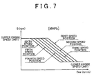
- an engine speed reference value B (a reference value that is set on the engine speed fluctuation amount of the internal combustion engine) is set according to an engine speed reference value setting map MAPb that is shown in FIG 7 and based on the engine speed deceleration Dne and the gear position SFT (S114).
- the map MAPb indicates that if the gear position is fixed, when the engine speed deceleration Dne is larger, in other words, when the average engine speed Nea more rapidly decreases, a smaller engine speed fluctuation amount is set as the engine speed reference value B.
- upper and lower limits (lower engine speed limit and upper engine speed limit in the drawing) are provided in a low range and a high range of the engine speed deceleration Dne, the reference value B converges into a certain engine speed fluctuation amount.
- the engine speed fluctuation amount reference value B when the gear position SFT is shifted to a higher gear position, a smaller engine speed fluctuation amount is set as the engine speed fluctuation amount reference value B on the map MAPb.
- the engine speed fluctuation amount reference value B may not become smaller as described above when the gear position SFT is shifted to a higher gear position, depending on types of the MT 28.
- the same engine speed fluctuation amount reference value B may be set for several gear positions.
- the magnitude correspondence between the gear position and the engine speed fluctuation amount reference value B may be reversed. Such a setting is to cope with change in the resonance rotational speed of the DMF 24 that occurs in response to the difference in the gear position SFT.
- the engine speed fluctuation amount reference value B converges into the same engine speed fluctuation amount for all the gear positions in the lower and higher ranges of the engine speed deceleration Dne.
- the engine speed fluctuation amount ⁇ Ne1 corresponds to the engine speed fluctuation amount reference value B in the higher range of the engine speed deceleration Dne.
- the engine speed fluctuation amount ⁇ Ne2 corresponds to the engine speed fluctuation amount reference value B in the intermediate range of the engine speed deceleration Dne.
- the engine speed fluctuation amount ⁇ Ne3 corresponds to the engine speed fluctuation amount reference value B in the lower range of the engine speed deceleration Dne.
- a range that such an engine speed fluctuation amount reference value B is set according to the map MAPb is set in the lower range that is away from an engine speed fluctuation amount ⁇ NeR at which resonance occurs.
- the engine speed fluctuation amount reference value B becomes smaller when the engine speed deceleration Dne is larger, the increasing engine speed fluctuation amount ⁇ Ne early reaches the engine speed fluctuation amount reference value B. Conversely, the engine speed fluctuation amount reference value B becomes larger when the engine speed deceleration Dne is smaller. Therefore, the engine speed fluctuation amount ⁇ Ne more slowly reaches the engine speed fluctuation amount reference value B than the case that the engine speed deceleration Dne is large, in other words, reaches the engine speed fluctuation amount reference value B after the engine speed fluctuation amount ⁇ Ne increases to a certain degree.
- resonance rotational speeds NeR1, NeR2, and NeR3 of the DMF 24 fall into different values in different gear positions.
- a same average engine speed Nea is a range that the engine speed fluctuation amount ⁇ Ne rapidly increases for the high gear position, a range that the engine speed fluctuation amount ⁇ Ne intermediately increases for the medium gear position, and a range that the engine speed fluctuation amount ⁇ Ne not rapidly increases for the low gear position. Therefore, on the map MAPb, the engine speed fluctuation reference value B is set to a small value for the high gear position, an intermediate value for the medium gear position, and a large value for the low gear position.
- the engine speed fluctuation amount reference value B is smaller when the MT 28 is in the higher gear position, the engine speed fluctuation amount ⁇ Ne that increases in response to decrease in the average engine speed Nea early reaches the engine speed fluctuation reference value B.
- the engine speed fluctuation amount reference value B is larger when the MT 28 is in the lower gear position. Therefore, even if the engine speed fluctuation amount ⁇ Ne increases to a certain degree, there is time for a fluctuation inhibiting process until the engine speed fluctuation amount ⁇ Ne reaches the engine speed fluctuation amount reference value B.
- Nea ⁇ A (“YES” in S116)
- a determination is next made about whether or not the engine speed fluctuation amount ⁇ Ne is larger than the engine speed fluctuation amount reference value B (S118). If Nea B ("NO" in S118), then the process is terminated.
- a rotational fluctuation inhibiting process (S120) is next executed. In other words, if a rotational fluctuation inhibiting condition that is provided by two conditions of "Nea ⁇ A" AND “ ⁇ Ne > B" is satisfied, the engine speed fluctuation inhibiting process (S120) is executed.
- the following processes are executed separately or in a combination. (1). Between the cylinders of the engine 2, either or both of differences in the fuel injection timing and the fuel injection amount by the fuel injection valves 4 are generated, thereby changing the frequency of the output fluctuation that is generated due to change in the crank angle of the engine 2. Accordingly, the average engine speed Nea is varied from the resonance rotational speed of the DMF 24.
- the fuel injection timing from the fuel injection valve 4 is retarded. Accordingly, the engine output is reduced.
- the rotational fluctuation inhibiting process (S120) is executed separately or in a combination with those processes thereby inhibiting an excessive torque shock due to resonance.
- the ECU 30 functions as an engine rotational state detecting unit, a rotational fluctuation inhibiting unit, and a rotational fluctuation inhibiting condition adjusting unit.
- the shift sensor 36 functions as a drive-train output transmitting state detecting unit.
- the engine rotational state detecting unit may execute the process for obtaining the average engine speed Nea and the engine speed fluctuation amount ⁇ Ne that is executed by the ECU 30 based on the detection value of the crankshaft rotational speed sensor 32.
- the rotational fluctuation inhibiting unit may execute the processes of steps S116, S118, and S120 that are executed by the ECU 30.
- the rotational fluctuation inhibiting condition adjusting unit may execute the processes of steps S112 and S114 that the engine speed reference value A and the engine speed fluctuation amount reference value B are set according to the maps MAPa and MAPb.
- the engine speed reference value A and the engine speed fluctuation reference value B are set (S112 and S114). Those reference values A and B are compared with the average engine speed Nea and the engine speed fluctuation amount ⁇ Ne, and thereby a determination is made about the state whether or not the engine rotational state approaches the resonance rotational speed (S116 and S118). If the engine rotational state approaches the resonance rotational speed ("YES" in both steps S116 and S118), the rotational fluctuation inhibiting process (S120) is executed. This inhibits strong resonance and an engine stall.
- Values of the engine speed reference value A and the engine speed fluctuation amount reference value B are adjusted based on the operating state of the engine 2 and the output transmitting state of the drive-train with the maps MAPa and MAPb ( FIGs. 4 and 7 ) (S112 and S114).
- the average engine speed Nea is calculated as the operating state of the engine 2.
- the engine speed reference value A is gradually set to a larger value between the lower engine speed limit for resonance inhibition and the upper engine speed limit for preventing an error determination, as shown in FIG 4 .
- the engine speed fluctuation amount reference value B is gradually set to a smaller value between the upper engine speed limit fluctuation amount for resonance inhibition and the lower engine speed limit fluctuation amount for preventing an error determination, as shown in FIG. 7 .
- FIGs. 9A to 9D indicate a case that the rotational fluctuation inhibiting process (S120) is executed later than an appropriate timing due to use of fixed engine speed reference value A and engine speed fluctuation amount reference value B.
- the changes in the instant engine speed Ne, the engine speed fluctuation amount, the vehicle acceleration g, and the torque fluctuation Nm of the crankshaft 2a are indicated in FIGs. 9A, 9B , 9C, and 9D , respectively.
- Each of the drawings shows that large vertical oscillation is generated and strong resonance is generated.
- FIG 8A to 8D in accordance with the first embodiment show that even if the engine finally stops, no large vertical oscillation is generated, and strong resonance can be inhibited.
- the maps MAPa and MAPb may be set to correspond to the sixth gear position and the gear positions near the sixth gear position.
- the engine speed deceleration Dne and the gear position SFT are together taken into consideration on the maps MAPa and MAPb. Accordingly, an engine stall due to such unnecessary decrease in the engine output may be inhibited.
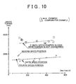
- the generated shock torque can be inhibited to a low level. Therefore, the shock torque to the DMF 24 can be retained lower than the fatigue limit torque according to Miner's law. Accordingly, the life of the DMF 24 can be made longer. This allows a sufficiently long guarantee period.
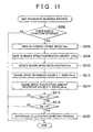
- FIG. 11 a process as demonstrated in FIG. 11 is executed as the DMF resonance inhibiting process.
- the configuration of the internal combustion engine is as shown in FIG. 1 .
- steps S202, S204, S206, S210, S216, S218, and S220 are the same processes as steps S102, S104, S106, S110, S116, S118, S120 in FIG. 2 .
- the engine speed reference value A is set according to a map MAPad shown in FIG. 12 and based only on the engine speed deceleration Dne in step S212
- the engine speed fluctuation amount reference value B is set according to a map MAPbd shown in FIG. 13 and based only on the engine speed deceleration Dne in step S214.
- the maps MAPad and MAPbd have, for example, settings based on the relationship between the engine speed deceleration Dne and the reference values A and B in the sixth gear position in the maps MAPa and MAPb that are shown in FIGs. 4 and 7 , or the relationship in the gear position near the sixth gear position.
- the rotational fluctuation inhibiting unit may execute the process of steps S216, S218, and S220 that are executed by the ECU 30.
- the rotational fluctuation inhibiting condition adjusting unit may execute the process of steps S212 and S214 that the engine speed reference value A and the engine speed fluctuation amount reference value B are set according to the maps MAPad and MAPbd.
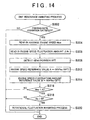
- FIG. 14 a process as demonstrated in FIG. 14 is executed as the DMF resonance inhibiting process.
- the configuration of the internal combustion engine is as shown in FIG. 1 .
- steps S302, S304, S306, S308, S316, S318, and S320 are the same processes as steps S102, S104, S106, S108, S116, S118, S120 in FIG. 2 .
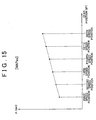
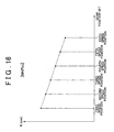
- the engine speed reference value A is set according to a map MAPas shown in FIG. 15 and based only on the gear position SFT in step S312, and the engine speed fluctuation amount reference value B is set according to a map MAPbs shown in FIG. 16 and based only on the gear position SFT in step S314.
- the engine speed reference value A is increased to a larger value for the higher gear positions so that the condition of step S316 among the rotational fluctuation inhibiting condition is early satisfied.
- the rotational fluctuation inhibiting unit may execute the process of steps S316, S318, and S320 that are executed by the ECU 30.
- the rotational fluctuation inhibiting condition adjusting unit may execute the process of steps S312 and S314 that the engine speed reference value A and the engine speed fluctuation amount reference value B are set according to the maps MAPas and MAPbs.
- the engine speed reference value A and the engine speed reference fluctuation reference value B are set (S312 and S314). Those reference values A and B are compared with the average engine speed Nea and the engine speed fluctuation amount ⁇ Ne, and thereby a determination is made about the state whether or not the engine speed approaches the resonance rotational speed (S316 and S318). If the engine speed approaches the resonance rotational speed ("YES" in both steps S316 and S318), the rotational fluctuation inhibiting process (S320) is executed. This inhibits strong resonance and an engine stall.
- Values of the engine speed reference value A and the engine speed fluctuation amount reference value B are adjusted based on the output transmitting state of the drive-train with the maps MAPas and MAPbs ( FIGs. 15 and 16 ) (S312 and S314).
- the engine speed reference value A is gradually set to a larger value based on the change in the resonance rotational speed according to the gear position SFT.
- the engine speed fluctuation amount reference value B is gradually set to a smaller value based on the change in the resonance rotational speed according to the gear position SFT.
- the reference values A and B are adjusted based on the output transmitting state from the engine 2 to the drive-train by the MT 28. This adjustment allows accurate determination about the approaching of the engine speed to the resonance rotational speed.
- the rotational fluctuation inhibiting process (S320) as the resonance inhibiting process can be executed at an appropriate timing. As a result, strong resonance and an engine stall can be inhibited.
- the reference values A and B are obtained with use of the rotational state of the crankshaft 2a (engine speed deceleration Dne).
- the rotational state of the crankshaft 2a (average engine speed Nea and engine speed fluctuation amount ⁇ Ne) is compared with the reference values A and B, thereby determining whether or not the rotational fluctuation inhibiting process (S120 or S220) is executed.
- the vehicle deceleration that is obtained from the vehicle speed detected by the vehicle speed sensor on the output shaft of the MT 28 may be obtained as a value corresponding to the rotational state of the crankshaft 2a.
- the reference values A and B may be obtained with the vehicle deceleration instead of the engine speed deceleration Dne.
- the reference values A and B are compared with the average engine speed Nea and the engine speed fluctuation amount ⁇ Ne, and thereby a determination may be made about whether or not the rotational fluctuation inhibiting process (S120 or S220) is executed.
- the engine speed reference value A and the engine speed fluctuation amount reference value B are compared with the average engine speed Nea and the engine speed fluctuation amount ⁇ Ne, respectively. However, only the engine speed reference value A is compared with the average engine speed Nea, and thereby a determination may be made about whether or not the rotational fluctuation inhibiting process (S120, S220, or S320) is executed. Otherwise, only the engine speed fluctuation amount reference value B is compared with the engine speed fluctuation amount ⁇ Ne, and thereby a determination may be made about whether or not the rotational fluctuation inhibiting process (S120, S220, or S320) is executed.
- step S120, S220, or S320 the processes (1) to (4) can be executed in a combination or separately.
- the rotational fluctuation inhibiting condition may be changed for each of the processes (1) to (4).
- a different map among the maps MAPa, MAPb, MAPad, MAPbd, MAPas, and MAPbs is selected for each of the processes (1) to (4), and thereby the rotational fluctuation inhibiting condition may be set.
- crankshaft rotational speed fluctuation corresponds to the work fluctuation of the crankshaft 2a. Therefore, the work fluctuation of the crankshaft 2a is calculated, and thereby the peak of the work fluctuation may be used as the engine speed fluctuation amount ⁇ Ne.
- each of the DMF resonance inhibiting processes ( FIGs. 2 , 11 , and 14 ) is executed with the peak value of the work fluctuation.
- the square value of the change in the engine speed in time corresponds to the work. Therefore, the resonance state may be determined with the square value of the change in the engine speed in time.
Landscapes
- Engineering & Computer Science (AREA)
- Chemical & Material Sciences (AREA)
- Combustion & Propulsion (AREA)
- Mechanical Engineering (AREA)
- Transportation (AREA)
- Automation & Control Theory (AREA)
- General Engineering & Computer Science (AREA)
- Control Of Vehicle Engines Or Engines For Specific Uses (AREA)
- Combined Controls Of Internal Combustion Engines (AREA)
- Electrical Control Of Air Or Fuel Supplied To Internal-Combustion Engine (AREA)
Claims (18)
- Steuereinrichtung für eine Verbrennungskraftmaschine, die über ein Zweimassenschwungrad (24) Leistung an einen Antriebsstrang überträgt, wobei die Steuereinrichtung aufweist:eine Motor-Rotationszustands-Erfassungseinheit (30), die Rotationsfluktuationen der Verbrennungskraftmaschine und eine Durchschnitts-Motordrehzahl der Verbrennungskraftmaschine (Nea) erfasst;eine Rotationsfluktuations-Hemmeinheit (30), die einen Vorgang ausführt, bei dem Rotationsfluktuationen der Verbrennungskraftmaschine gehemmt werden,wenn eine Rotationsfluktuationshemmbedingung erfüllt wird, wobei die Rotationsfluktuationshemmbedingung eine Bedingung ist, derzufolge ein tatsächlicher Motordrehzahlfluktuationswert der Verbrennungskraftmaschine größer ist als ein Referenzwert, der für den Motordrehzahlfluktuationswert der Verbrennungskraftmaschine eingestellt wird; undeine Rotationsfluktuationshemmbedingungs-Einstelleinheit (30), die den Referenzwert verringert, so dass die Rotationsfluktuationshemmbedingung früher erfüllt wird, wenn die Verlangsamung der Durchschnitts-Motordrehzahl der Verbrennungskraftmaschine (Nea), die von der Motor-Rotationszustands-Erfassungseinheit erfasst wird, größer ist.
- Steuereinrichtung nach Anspruch 1, wobei die Rotationsfluktuationshemmbedingungs-Einstelleinheit verwendet werden kann, um den Motordrehzahlfluktuations-Referenzwert, über dem die Rotationsfluktuationshemmbedingung erfüllt wird, so zu verringern, dass die Rotationsfluktuationshemmbedingung früher erfüllt wird, wenn der Rotationszustand, der von der Motor-Rotationszustands-Erfassungseinheit erfasst wird, sich leichter der Resonanz-Rotationsgeschwindigkeit des Zweimassenschwungrads annähert, was geschieht, wenn die Schaltposition auf eine höhere Position geschaltet wird.
- Steuereinrichtung nach Anspruch 1 oder 2, wobei die Motor-Rotationszustands-Erfassungseinheit eine Durchschnitts-Motordrehzahl der Verbrennungskraftmaschine als den Rotationszustand erfasst, die Rotationsfluktuations-Hemmeinheit als Rotationsfluktuationshemmbedingung eine Bedingung einstellt, derzufolge eine tatsächliche Durchschnitts-Motordrehzahl der Verbrennungskraftmaschine geringer ist als ein Referenzwert, der für die Durchschnitts-Motordrehzahl der Verbrennungskraftmaschine eingestellt wird, und die Rotationsfluktuations-Hemmbedingungs-Einstelleinheit den Referenzwert so einstellt, dass die Rotationsfluktuationshemmbedingung früher erfüllt wird, wenn die Verlangsamung der Durchschnitts-Motordrehzahl der Verbrennungskraftmaschine, die von der Motor-Rotationszustands-Erfassungseinheit erfasst wird, größer ist.
- Steuereinrichtung nach Anspruch 3, wobei die Rotationsfluktuations-Hemmbedingungs-Einstelleinheit den Referenzwert auf einen größeren Wert erhöht, wenn die Verlangsamung der Durchschnitts-Motordrehzahl der Verbrennungskraftmaschine, die von der Motor-Rotationszustands-Erfassungseinheit erfasst wird, größer ist.
- Steuereinrichtung nach Anspruch 1, wobei die Rotationsfluktuations-Hemmbedingungs-Einstelleinheit den Referenzwert auf einen niedrigeren Wert verringert, wenn die Verlangsamung der Durchschnitts-Motordrehzahl der Verbrennungskraftmaschine, die von der Motor-Rotationszustands-Erfassungseinheit erfasst wird, größer ist.
- Steuereinrichtung nach Anspruch 1 oder 5, wobei die Rotationsfluktuations-Hemmeinheit als Rotationsfluktuationshemmbedingung eine Bedingung einstellt, derzufolge eine tatsächliche Durchschnitts-Motordrehzahl der Verbrennungskraftmaschine niedriger als der Referenzwert ist, der für die Durchschnitts-Motordrehzahl der Verbrennungskraftmaschine eingestellt wird, und ein tatsächlicher Motordrehzahlfluktuationswert der Verbrennungskraftmaschine größer als der Referenzwert ist, der für den Motordrehzahlfluktuationswert der Verbrennungskraftmaschine eingestellt wird, und die Rotationsfluktuations-Hemmeinheit den Vorgang des Hemmens von Rotationsfluktuationen für die Verbrennungskraftmaschine ausführt, wenn die beiden Bedingungen erfüllt sind.
- Steuereinrichtung nach einem der Ansprüche 1 bis 6, wobei die Verbrennungskraftmaschine zum Antreiben eines Fahrzeugs bestimmt ist und die Motor-Rotationszustands-Erfassungseinheit eine Verlangsamung des Fahrzeugs als den Rotationszustand der Verbrennungskraftmaschine erfasst.
- Steuereinrichtung nach einem der Ansprüche 1 bis 7, ferner aufweisend:eine Antriebsstrang-Leistungsübertragungszustands-Erfassungseinheit (36), die einen Leistungsübertragungszustand des Antriebsstrangs erfasst;wobei die Rotationsfluktuations-Hemmbedingungs-Einstelleinheit einen Einstellzustand der Rotationsfluktuationshemmbedingung auf Basis eines Leistungsübertragungszustands ändert, der von der Antriebsstrang-Leistungsübertragungszustands-Erfassungseinheit erfasst wird.
- Steuereinrichtung nach Anspruch 8, wobei die Rotationsfluktuations-Hemmbedingungs-Einstelleinheit den Einstellzustand der Rotationsfluktuationshemmbedingung auf Basis der Resonanz-Rotationsgeschwindigkeit des Zweimassenschwungrads ändert, die sich als Reaktion auf den Leistungsübertragungszustand, der von der Antriebsstrang-Leistungsübertragungszustands-Erfassungseinheit erfasst wird, ändert.
- Steuereinrichtung nach Anspruch 8 oder 9, wobei der Antriebsstrang ein Getriebe (28) beinhaltet und die Antriebsstrang-Leistungsübertragungszustands-Erfassungseinheit eine Schaltposition des Getriebes als den Leistungsübertragungszustand des Antriebsstrangs erfasst.
- Steuereinrichtung nach Anspruch 1, ferner aufweisend:eine Antriebsstrang-Leistungsübertragungszustands-Erfassungseinheit (36), die einen Leistungsübertragungszustand des Antriebsstrangs erfasst.
- Steuereinrichtung nach Anspruch 11, wobei der Antriebsstrang ein Getriebe (28) beinhaltet und die Antriebsstrang-Leistungsübertragungszustands-Erfassungseinheit eine Schaltposition des Getriebes als den Leistungsübertragungszustand des Antriebsstrangs erfasst.
- Steuereinrichtung nach Anspruch 11 oder 12, wobei die Rotationsfluktuations-Hemmbedingungs-Einstelleinheit die Rotationsfluktuationshemmbedingung so einstellt, dass die Rotationsfluktuationshemmbedingung früher erfüllt wird, wenn der Leistungsübertragungszustand, der von der Antriebsstrang-Leistungsübertragungszustands-Erfassungseinheit erfasst wird, sich leichter der Resonanz-Rotationsgeschwindigkeit des Zweimassenschwungrads (24) annähert.
- Steuereinrichtung nach einem der Ansprüche 11 bis 13, wobei die Rotationsfluktuations-Hemmbedingungs-Einstelleinheit die Rotationsfluktuationshemmbedingung auf Basis der Resonanz-Rotationsgeschwindigkeit des Zweimassenschwungrads (24) einstellt, die dem Leistungsübertragungszustand entspricht, der von der Antriebsstrang-Leistungsübertragungszustands-Erfassungseinheit erfasst wird.
- Steuereinrichtung nach Anspruch 14, wobei die Motor-Rotationszustands-Erfassungseinheit eine Durchschnitts-Motordrehzahl der Verbrennungskraftmaschine als den Rotationszustand erfasst, die Rotationsfluktuations-Hemmeinheit als Rotationsfluktuationshemmbedingung eine Bedingung einstellt, derzufolge eine tatsächliche Durchschnitts-Motordrehzahl der Verbrennungskraftmaschine geringer ist als ein Referenzwert, der für die Durchschnitts-Motordrehzahl der Verbrennungskraftmaschine eingestellt wird, und die Rotationsfluktuations-Hemmbedingungs-Einstelleinheit den Referenzwert auf einen größeren Wert erhöht, wenn die Resonanz-Rotationsgeschwindigkeit, die dem Leistungsübertragungszustand entspricht, der von der Antriebsstrang-Leistungsübertragungszustands-Erfassungseinheit erfasst wird, höher ist, und somit die Rotationsfluktuationshemmbedingung so einstellt, dass die Bedingung früher erfüllt wird.
- Steuereinrichtung nach Anspruch 14, wobei die Motor-Rotationszustands-Erfassungseinheit Rotationsfluktuationen der Verbrennungskraftmaschine als Rotationszustand erfasst, die Rotationsfluktuations-Hemmeinheit als Rotationsfluktuationshemmbedingung eine Bedingung einstellt, derzufolge ein tatsächlicher Motordrehzahl-Fluktuationswert der Verbrennungskraftmaschine größer ist als ein Referenzwert, der für den Motordrehzahl-Fluktuationswert der Verbrennungskraftmaschine eingestellt wird, und die Rotationsfluktuations-Hemmbedingungs-Einstelleinheit den Referenzwert auf einen niedrigeren Wert verringert, wenn die Resonanz-Rotationsgeschwindigkeit, die dem Leistungsübertragungszustand entspricht, der von der Antriebsstrang-Leistungsübertragungszustands-Erfassungseinheit erfasst wird, höher ist, und somit die Rotationsfluktuationshemmbedingung so einstellt, dass die Bedingung früher erfüllt wird.
- Steuereinrichtung nach Anspruch 16, wobei die Rotationsfluktuations-Hemmeinheit als Rotationsfluktuationshemmbedingung eine Bedingung einstellt, derzufolge eine tatsächliche Durchschnitts-Motordrehzahl der Verbrennungskraftmaschine niedriger ist als der Referenzwert, der für die Durchschnitts-Motordrehzahl der Verbrennungskraftmaschine eingestellt wird, und ein tatsächlicher Motordrehzahl-Fluktuationswert der Verbrennungskraftmaschine größer ist als der Referenzwert, der für den Motordrehzahl-Fluktuationswert der Verbrennungskraftmaschine eingestellt wird, und den Vorgang des Hemmens von Rotationsfluktuationen für die Verbrennungskraftmaschine ausführt, wenn beide Bedingungen erfüllt sind.
- Steuereinrichtung nach einem der Ansprüche 1 bis 17, wobei die Rotationsfluktuations-Hemmeinheit entweder die Verringerung der Leistung der Verbrennungskraftmaschine oder eine Änderung der Leistungsfluktuationsfrequenz der Verbrennungskraftmaschine oder beides herbeiführt, wodurch ein Vorgang des Hemmens von Rotationsfluktuationen der Verbrennungskraftmaschine zur Ausführung gelangt.
Applications Claiming Priority (1)
| Application Number | Priority Date | Filing Date | Title |
|---|---|---|---|
| JP2008199930A JP4670912B2 (ja) | 2008-08-01 | 2008-08-01 | 内燃機関制御装置 |
Publications (2)
| Publication Number | Publication Date |
|---|---|
| EP2149694A1 EP2149694A1 (de) | 2010-02-03 |
| EP2149694B1 true EP2149694B1 (de) | 2014-05-14 |
Family
ID=41137259
Family Applications (1)
| Application Number | Title | Priority Date | Filing Date |
|---|---|---|---|
| EP09166873.1A Ceased EP2149694B1 (de) | 2008-08-01 | 2009-07-30 | Vorrichtung zur Steuerung eines Verbrennungsmotors |
Country Status (3)
| Country | Link |
|---|---|
| US (1) | US7934485B2 (de) |
| EP (1) | EP2149694B1 (de) |
| JP (1) | JP4670912B2 (de) |
Families Citing this family (18)
| Publication number | Priority date | Publication date | Assignee | Title |
|---|---|---|---|---|
| DE102009018081B4 (de) * | 2009-04-20 | 2011-01-13 | Continental Automotive Gmbh | Verfahren und Vorrichtung zum Betreiben einer Brennkraftmaschine |
| JP5334678B2 (ja) * | 2009-05-14 | 2013-11-06 | トヨタ自動車株式会社 | 車両駆動システムの制御装置 |
| US8086391B2 (en) * | 2010-11-02 | 2011-12-27 | Ford Global Technologies Llc | Vehicle launch anticipation |
| US9103646B2 (en) | 2010-12-21 | 2015-08-11 | Bradford W. Bur | Active fuel management systems and methods for vehicles with a manual transmission |
| US8874337B2 (en) | 2011-09-06 | 2014-10-28 | GM Global Technology Operations LLC | System and method for controlling loads on a manual transmission based on a selected gear of the manual transmission |
| US8798880B2 (en) * | 2011-09-23 | 2014-08-05 | GM Global Technology Operations LLC | System and method for controlling loads on a dual mass flywheel attached to an engine based on engine speed |
| DE102011115927A1 (de) * | 2011-10-13 | 2013-04-18 | Audi Ag | Verfahren und Vorrichtung zum Erkennen von Drehzahl-/Drehmomentschwankungen in einer Antriebsvorrichtung |
| US9656665B2 (en) * | 2012-05-04 | 2017-05-23 | Ford Global Technologies, Llc | Methods and systems for a driveline dual mass flywheel |
| DE102014205136A1 (de) * | 2014-03-19 | 2015-09-24 | Zf Friedrichshafen Ag | Hybridmodul sowie Antriebsstrang mit dem Hybridmodul |
| CN104198181B (zh) * | 2014-07-31 | 2017-02-01 | 长城汽车股份有限公司 | 双质量飞轮的共振检测方法及系统 |
| JP6149833B2 (ja) * | 2014-09-12 | 2017-06-21 | トヨタ自動車株式会社 | 内燃機関の制御装置 |
| DE102014219043A1 (de) | 2014-09-22 | 2016-03-24 | Volkswagen Ag | Antriebsstrang einer Brennkraftmaschine und Verfahren zur Erkennung von Zündaussetzern der Brennkraftmaschine |
| DE102015101005B4 (de) * | 2015-01-23 | 2022-12-08 | Dr. Ing. H.C. F. Porsche Aktiengesellschaft | Verfahren zum Starten eines Kraftfahrzeugmotors sowie Motorsteuergerät zur Steuerung eines Kraftfahrzeugmotors |
| CN104929786A (zh) * | 2015-05-12 | 2015-09-23 | 安徽江淮汽车股份有限公司 | 车辆断油控制方法及装置 |
| CN107664083B (zh) * | 2016-07-28 | 2019-09-27 | 一汽海马汽车有限公司 | 用于保护汽车发动机的飞轮的方法及系统 |
| US10731582B2 (en) * | 2016-11-16 | 2020-08-04 | GM Global Technology Operations LLC | Determination of engine parameter based on determining a metric over three or more cylinder combustion cycles |
| JP6624034B2 (ja) * | 2016-12-13 | 2019-12-25 | トヨタ自動車株式会社 | 車両の制御装置 |
| CN113586270A (zh) * | 2021-07-19 | 2021-11-02 | 东风汽车集团股份有限公司 | 一种发动机双质量飞轮的保护方法和存储介质 |
Family Cites Families (25)
| Publication number | Priority date | Publication date | Assignee | Title |
|---|---|---|---|---|
| JPS5623564A (en) * | 1979-08-06 | 1981-03-05 | Nippon Denso Co Ltd | Method of controlling energizing time of ignition coil |
| JPS5985442A (ja) * | 1982-11-08 | 1984-05-17 | Toyota Motor Corp | 二分割フライホイ−ルのトルク変動低減装置 |
| JPS5985443A (ja) | 1982-11-08 | 1984-05-17 | Toyota Motor Corp | 二分割フライホイ−ルのトルク変動低減装置 |
| GB8700758D0 (en) * | 1987-01-14 | 1987-02-18 | Lucas Ind Plc | Adaptive control system |
| JPH01173818A (ja) * | 1987-12-28 | 1989-07-10 | Aisin Aw Co Ltd | 車両用ナビゲーション装置 |
| JPH0821290A (ja) * | 1994-07-06 | 1996-01-23 | Honda Motor Co Ltd | 内燃機関の電子制御システムのセンサ異常処理装置 |
| JP3731025B2 (ja) * | 1996-08-09 | 2006-01-05 | 三菱自動車工業株式会社 | 内燃機関の空気量制御装置 |
| DE19724921C2 (de) | 1997-06-12 | 1999-08-12 | Mannesmann Sachs Ag | Antriebssystem für ein Kraftfahrzeug und Verfahren zum Betreiben einer Brennkraftmaschine |
| JP3767258B2 (ja) * | 1999-07-28 | 2006-04-19 | 株式会社デンソー | At車のエンジン自動停止装置 |
| JP3890827B2 (ja) * | 1999-09-28 | 2007-03-07 | トヨタ自動車株式会社 | 内燃機関の制御装置 |
| JP2002047982A (ja) * | 2000-08-03 | 2002-02-15 | Honda Motor Co Ltd | 内燃機関の制御装置 |
| JP3991674B2 (ja) * | 2001-12-18 | 2007-10-17 | 株式会社デンソー | 内燃機関の制御装置 |
| US6993426B2 (en) * | 2003-07-14 | 2006-01-31 | Detroit Diesel Corporation | Method of engine overspeed protection by inhibiting operator throttle input |
| JP4135587B2 (ja) | 2003-08-05 | 2008-08-20 | いすゞ自動車株式会社 | エンジンの始動時制御方法及び装置 |
| JP3982506B2 (ja) * | 2004-02-17 | 2007-09-26 | 株式会社デンソー | 内燃機関の噴射量制御装置 |
| JP4066971B2 (ja) * | 2004-03-29 | 2008-03-26 | トヨタ自動車株式会社 | 内燃機関の制御装置 |
| JP4539211B2 (ja) * | 2004-07-23 | 2010-09-08 | 日産自動車株式会社 | 内燃機関の制御装置 |
| JP2006183484A (ja) | 2004-12-27 | 2006-07-13 | Nissan Motor Co Ltd | 内燃機関の制御装置 |
| JP4529832B2 (ja) * | 2005-07-26 | 2010-08-25 | 日産自動車株式会社 | 筒内直接噴射式火花点火内燃機関の制御装置 |
| JP3927584B2 (ja) * | 2005-10-26 | 2007-06-13 | 三菱電機株式会社 | 自動車用動力制御装置 |
| JP4731401B2 (ja) * | 2006-05-19 | 2011-07-27 | ヤマハ発動機株式会社 | 船舶用推進機の電子式遠隔制御装置及び船舶 |
| JP4916867B2 (ja) * | 2006-12-18 | 2012-04-18 | 富士重工業株式会社 | ディーゼルエンジンの停止制御装置 |
| US7698052B2 (en) * | 2007-02-09 | 2010-04-13 | Yamaha Hatsudoki Kabushiki Kaisha | Engine rotation control device and boat |
| JP4433018B2 (ja) | 2007-08-31 | 2010-03-17 | トヨタ自動車株式会社 | 内燃機関制御装置 |
| JP4483937B2 (ja) | 2007-12-13 | 2010-06-16 | トヨタ自動車株式会社 | エンジンの制御装置および制御方法 |
-
2008
- 2008-08-01 JP JP2008199930A patent/JP4670912B2/ja not_active Expired - Fee Related
-
2009
- 2009-07-29 US US12/461,014 patent/US7934485B2/en not_active Expired - Fee Related
- 2009-07-30 EP EP09166873.1A patent/EP2149694B1/de not_active Ceased
Also Published As
| Publication number | Publication date |
|---|---|
| US7934485B2 (en) | 2011-05-03 |
| US20100024768A1 (en) | 2010-02-04 |
| JP4670912B2 (ja) | 2011-04-13 |
| EP2149694A1 (de) | 2010-02-03 |
| JP2010037988A (ja) | 2010-02-18 |
Similar Documents
| Publication | Publication Date | Title |
|---|---|---|
| EP2149694B1 (de) | Vorrichtung zur Steuerung eines Verbrennungsmotors | |
| US7509201B2 (en) | Sensor feedback control for noise and vibration | |
| US5431139A (en) | Air induction control system for variable displacement internal combustion engine | |
| EP2227625B1 (de) | Vorrichtung zur steuerung der übergangsphase eines brennstoffverbrauchsstatus eines verbrennungsmotors | |
| EP2031223B1 (de) | Regler für Verbrennungsmotor | |
| JP2006291803A (ja) | エンジンのトルク制御装置とそれを備えた車両制御システム | |
| CN102052174A (zh) | 发动机的控制装置 | |
| US8033266B2 (en) | Throttle valve controller for internal combustion engine | |
| EP2071163A2 (de) | Steuerungseinrichtung für Brennkraftmaschine und Motorsteuerungsverfahren | |
| EP2230393A2 (de) | System und Verfahren zur Detektion der Verbrennungsmotorresonanz beim Start und Verbrennungsmotorsteuerung | |
| JP5171738B2 (ja) | 電制スロットル特性学習制御装置及び方法 | |
| JP2010127105A (ja) | 内燃機関制御装置 | |
| EP2123886B1 (de) | Fahrzeugantriebssteuerungsvorrichtung | |
| KR20020086708A (ko) | 차량의 구동 유닛 제어 방법 및 장치 | |
| JP2010203249A (ja) | 内燃機関制御装置 | |
| JP2004100528A (ja) | 内燃機関の点火時期制御装置 | |
| JP4508995B2 (ja) | 車両用パワートレイン制御装置 | |
| JP2560501B2 (ja) | 車両用排気ターボチャージャ付エンジンの過給圧制御装置 | |
| JP4409065B2 (ja) | エンジンのアイドル制御弁の制御装置 | |
| JP7468323B2 (ja) | 内燃機関の燃料噴射制御装置 | |
| JP4884337B2 (ja) | 内燃機関の制御装置 | |
| JP6079952B2 (ja) | エンジンの制御装置 | |
| JPH11200928A (ja) | 車両用エンジンのアイドル回転数制御装置 | |
| JP2023161735A (ja) | エンジンのトルク異常判定装置及びそれを備えたハイブリッド車両 | |
| JP6365840B2 (ja) | 内燃機関のバランサ装置 |
Legal Events
| Date | Code | Title | Description |
|---|---|---|---|
| PUAI | Public reference made under article 153(3) epc to a published international application that has entered the european phase |
Free format text: ORIGINAL CODE: 0009012 |
|
| 17P | Request for examination filed |
Effective date: 20090814 |
|
| AK | Designated contracting states |
Kind code of ref document: A1 Designated state(s): AT BE BG CH CY CZ DE DK EE ES FI FR GB GR HR HU IE IS IT LI LT LU LV MC MK MT NL NO PL PT RO SE SI SK SM TR |
|
| AX | Request for extension of the european patent |
Extension state: AL BA RS |
|
| 17Q | First examination report despatched |
Effective date: 20111125 |
|
| RAP1 | Party data changed (applicant data changed or rights of an application transferred) |
Owner name: TOYOTA JIDOSHA KABUSHIKI KAISHA |
|
| GRAP | Despatch of communication of intention to grant a patent |
Free format text: ORIGINAL CODE: EPIDOSNIGR1 |
|
| INTG | Intention to grant announced |
Effective date: 20131217 |
|
| RIN1 | Information on inventor provided before grant (corrected) |
Inventor name: SAIGO, YUSUKE Inventor name: OTA, MASAYOSHI Inventor name: ITO, YOSHIYASU |
|
| GRAS | Grant fee paid |
Free format text: ORIGINAL CODE: EPIDOSNIGR3 |
|
| GRAA | (expected) grant |
Free format text: ORIGINAL CODE: 0009210 |
|
| RBV | Designated contracting states (corrected) |
Designated state(s): DE |
|
| AK | Designated contracting states |
Kind code of ref document: B1 Designated state(s): DE |
|
| REG | Reference to a national code |
Ref country code: DE Ref legal event code: R096 Ref document number: 602009024064 Country of ref document: DE Effective date: 20140703 |
|
| REG | Reference to a national code |
Ref country code: DE Ref legal event code: R097 Ref document number: 602009024064 Country of ref document: DE |
|
| PLBE | No opposition filed within time limit |
Free format text: ORIGINAL CODE: 0009261 |
|
| STAA | Information on the status of an ep patent application or granted ep patent |
Free format text: STATUS: NO OPPOSITION FILED WITHIN TIME LIMIT |
|
| REG | Reference to a national code |
Ref country code: DE Ref legal event code: R084 Ref document number: 602009024064 Country of ref document: DE |
|
| 26N | No opposition filed |
Effective date: 20150217 |
|
| REG | Reference to a national code |
Ref country code: DE Ref legal event code: R097 Ref document number: 602009024064 Country of ref document: DE Effective date: 20150217 |
|
| REG | Reference to a national code |
Ref country code: DE Ref legal event code: R084 Ref document number: 602009024064 Country of ref document: DE Effective date: 20150417 |
|
| PGFP | Annual fee paid to national office [announced via postgrant information from national office to epo] |
Ref country code: DE Payment date: 20210630 Year of fee payment: 13 |
|
| REG | Reference to a national code |
Ref country code: DE Ref legal event code: R119 Ref document number: 602009024064 Country of ref document: DE |
|
| PG25 | Lapsed in a contracting state [announced via postgrant information from national office to epo] |
Ref country code: DE Free format text: LAPSE BECAUSE OF NON-PAYMENT OF DUE FEES Effective date: 20230201 |