EP2150478B1 - Conteneur de déchets avec un dispositif de décharge - Google Patents
Conteneur de déchets avec un dispositif de décharge Download PDFInfo
- Publication number
- EP2150478B1 EP2150478B1 EP08780645.1A EP08780645A EP2150478B1 EP 2150478 B1 EP2150478 B1 EP 2150478B1 EP 08780645 A EP08780645 A EP 08780645A EP 2150478 B1 EP2150478 B1 EP 2150478B1
- Authority
- EP
- European Patent Office
- Prior art keywords
- storage tank
- debris
- extension
- plate
- extension arm
- Prior art date
- Legal status (The legal status is an assumption and is not a legal conclusion. Google has not performed a legal analysis and makes no representation as to the accuracy of the status listed.)
- Active
Links
- 238000004140 cleaning Methods 0.000 claims description 15
- 238000000034 method Methods 0.000 description 7
- 239000010865 sewage Substances 0.000 description 7
- XLYOFNOQVPJJNP-UHFFFAOYSA-N water Substances O XLYOFNOQVPJJNP-UHFFFAOYSA-N 0.000 description 2
- 230000004075 alteration Effects 0.000 description 1
- 238000010276 construction Methods 0.000 description 1
- 230000005484 gravity Effects 0.000 description 1
- 239000000463 material Substances 0.000 description 1
- 239000007787 solid Substances 0.000 description 1
- 238000006467 substitution reaction Methods 0.000 description 1
Images


Classifications
-
- E—FIXED CONSTRUCTIONS
- E03—WATER SUPPLY; SEWERAGE
- E03F—SEWERS; CESSPOOLS
- E03F7/00—Other installations or implements for operating sewer systems, e.g. for preventing or indicating stoppage; Emptying cesspools
- E03F7/10—Wheeled apparatus for emptying sewers or cesspools
Definitions
- This invention relates to a device for unloading debris from a vehicle-mounted storage tank into a dump box, and more particularly, the invention relates to a debris storage tank emptying system having extension plate that moves axially within the storage tank to assist in the unloading process.
- Sewage cleaning vehicles are specially designed vehicles for cleaning sewers, storm drains, and catch basins and for transporting collected debris to a dumpsite.
- a storage tank mounted on the vehicle holds the collected debris until it is transported to a dumpsite.
- the vehicle operator typically dumps the debris into a dump box.
- Crew members manually assist in removing debris from the storage tank.
- DE 1932653A discloses a device according to the pre-characterising portion of claim 1.
- the present invention provides a new apparatus that overcomes the above and other shortcomings of the known art.
- the inventive apparatus allows an operator to more evenly distribute debris in a dump box without the need for crew members to manually spread the debris.
- the extension arm may also be 121,9 cm (4 feet) long.
- the extension arm of the debris storage tank emptying system may be generally parallel to the inner floor of said storage tank when said extension plate is within said storage tank and said extension arm may be configured to angled downward when said extension plate is outside of said storage tank. Additionally, the extension plate may be pivotally attached to said extension arm so that it is generally perpendicular to said extension arm when said pusher plate is being moved toward the opening in said storage tank. The extension plate may be pivotally attached to said extension arm to reduce resistance from debris when said pusher plate is moved toward the retracted position.
- An extension plate assembly may further include a support arm extending from said extension arm and engaging said extension plate when said extension plate is pushing debris.
- the support arm may maintain said extension plate generally perpendicular to said extension arm when said extension arm is pushed by a pusher plate.
- the support arm may be unitary with said extension arm.
- the extension plate assembly may further comprise an auxiliary support arm extending from said extension arm, wherein said auxiliary support arm is configured to follow a path inside a storage tank. Additionally or alternatively, the auxiliary support arm may limit the clockwise angular rotation of said extension arm.
- the extension arm may have a cross section that maintains said extension plate in a generally perpendicular position with respect to said extension arm when said extension arm is pushed by a pusher plate.
- the extension arm may be sized to extend the length of a storage tank.
- the assembly may also include more then one extension arm. For example, two extension arms may be used.
- a sewer cleaning vehicle according to claim 11.
- the extension plate may be configured to push debris away from said debris collection tank but not pull debris toward said debris collection tank.
- the length of said extension arm is equal to or less than the distance said pusher plate travels between its most retracted position and its most extended position.
- the sewer clearing vehicle may also include positionable debris guides.
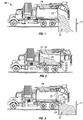
- FIG. 1 shows sewage utility cleaning vehicle (10).
- the vehicle includes pusher plate (13) that can be moved forward and backward within storage tank (14).
- debris (12) piles up at the edge of dump box (11).
- the crew distributes debris (12) in the dump box using shovels or the like.
- FIG. 2 shows a sewage utility cleaning vehicle equipped with the novel extension plate assembly (20).
- the extension plate assembly (20) is mounted on pusher plate (13) and moves with pusher plate (13) axially within the storage tank (14).
- Extension plate (22) may ride on wear pads (not shown) as it slides backwards and forwards in storage tank (14).
- FIG. 3 shows extension plate assembly (20) in an extended position.
- the extension plate assembly has extension arms (21) that are attached to pusher plate (13) at hinges (23) (See FIG. 4A ).
- the extension plate assembly (20) rotates about hinges (23) and extension plate (22) drops downward into dumb box (11).
- pusher plate (13) pushes extension plate assembly (20) downward and into dump box (11), moving debris (12) away from the edge of dump box (11).
- extension plate assembly (20) protrudes from storage tank (14) into dump box (11).
- the dumping system may include debris guiding structures that can be attached to the vehicle on the outer rim of the storage tank near the open end.
- the guiding structures direct the debris into the dump box and prevent spillage out of the sides of the storage tank during the dumping process.
- the debris guide structures including upper right and left side guides (31) (shown with a dashed line), lower right and left side guides (32), right and left lower guide plates (33), and a water shed (34).
- the upper right and left side guides are welded to the outer rim of storage tank (14), but other rotatable attachments are envisioned.
- the lower right and left side guides, lower guide plate, and water shed are preferably rotatably attached to the rim of the tank.
- the rotatable guides are adjusted from a vertical hanging position to a substantially horizontal engaged position for better directing the debris outward away from the tank and into dump box (11).
- FIGS 4A and 4B show an extension plate assembly (20).
- Extension plate assembly (20) includes extension arms (21), which in one embodiment are rectangular, that transmit the axial force from pusher plate (13) to extension plate (22) during use. Although two extension arms (21) are shown, any number may be used. Extension arms (21) are sized to push debris into dump box (11).
- Fig 2 shows extension arms (21) as being relatively short compared to the length of storage tank (14). However, one skilled in the art readily understand the arms can be made much longer. For example, the arms can be made so that the extension plate (22) is just inside the opening of storage tank (14) when pusher plate (13) is in its most retracted (forward) position.
- Extension plate (22) is preferably shaped to match storage tank (14) and has a surface area less than that of pusher plate (13). Extension plate (22) is shown as being solid, but one skilled in the art readily understands that it may be mesh, wire, or combinations thereof. Extension plate (22) is rotatably coupled to the extension arms (21) by hinges (23), allowing extension plate (22) to rotate from a vertical to a more horizontal position during use. Support arms (24) extend from extension arms (21) to provide axial support against extension plate (22) as it pushes debris out of the tank and into dump box (11). Although support arms (24) are shown as arms, one skilled in the art readily understands "support arms” as used herein can be any shape. For example, the support arms can be a triangular or rectangular.
- support arms can be the lower portion of extension arms (21). Still further, support arms can be part of extension plate (22). Support arms (24) keep extension plate (22) in a generally vertical position as the assembly moves backward (toward the opening) in storage tank (14). As extension plate assembly (20) is retracted (moves forward in the tank toward the front of truck (10)), the extension plate is free to pivot (rotate) counter-clockwise to a more horizontal position to pass over debris that may exist between the pusher plate and extension plate. Although some debris may be pulled toward the truck when the pusher plate is being retracted, extension plate (22) should pivot easy enough to ride on top of most of the debris while being retracted.
- One embodiment includes auxiliary support arms (26) shaped to guide the path of extension plate (22) as extension plate assembly (20) is moved backward and out of storage tank (14).
- support arms (26) may engage a wedge on the bottom of storage tank (14) (not shown). As support arms (26) move up and over the wedge, extension plate (22) is lifted off of the bottom of storage tank (14).
- Another example of how support arms (26) can be shaped to guide extension plate (22) is by limiting how low into dump box (11) extension plate (22) can extend. In limiting the lower extension, support arms (26) essentially create an optimal pushing angle between pusher plate (13) and the debris pile after the extension plate has cleared the back of storage tank (14).
- Support arm (26) is preferably shaped to allow extension arm (21) to hang at a specific angle relative to pusher plate (13) when the assembly is fully extended.
- material in the holding tank of a sewage utility cleaning vehicle is dumped as follows: The vehicle is backed to the edge of dump box (11). The debris guides and plates are locked into their dump positions. The tank lid is opened and the dumping of debris begins.
- truck (10) includes a control switch positioned within sight of the dump box (11) and storage tank (14). The control switch can be used to control movement of pusher plate (13).
- pusher plate (13) is moved toward the back of truck (10).
- extension plate assembly (20) helps spread the debris pile in dump box (11).
- the pusher plate (13) is then retracted (moved toward the front of truck (10)). The process may be repeated multiple time to fully spread the debris pile in dump box (11).
- the lid is closed, the debris guides are restored to their transport position, and the vehicle is readied for movement.
Landscapes
- Health & Medical Sciences (AREA)
- Life Sciences & Earth Sciences (AREA)
- Engineering & Computer Science (AREA)
- Hydrology & Water Resources (AREA)
- Public Health (AREA)
- Water Supply & Treatment (AREA)
- Refuse-Collection Vehicles (AREA)
- Refuse Collection And Transfer (AREA)
- Cleaning In General (AREA)
Claims (15)
- Système de vidange de réservoir de stockage de débris comprenant,
un réservoir de stockage (14) avec un plancher intérieur et une ouverture à l'intérieur pour vider les débris ;
une plaque de poussée (13) configurée pour pousser les débris hors de l'ouverture du réservoir de stockage (14), mobile à l'intérieur dudit réservoir de stockage (14) entre une position rétractée et une position étendue, dans lequel la position étendue est proche de l'ouverture dudit réservoir de stockage (14) ;
un bras d'extension (21) positionné à l'intérieur dudit réservoir de stockage (14) entre ladite plaque de poussée (13) et l'ouverture dudit réservoir de stockage (14) et configuré pour se déplacer avec ladite plaque de poussée (13) ; dans lequel ledit bras d'extension (21) s'étend au-delà de l'ouverture dans ledit réservoir de stockage (14) lorsque ladite plaque de poussée (13) est dans la position étendue ; et
une plaque d'extension (22) fixée audit bras d'extension (21), dans lequel ladite plaque d'extension (22) est configurée pour pousser les débris (12), et dans lequel ledit bras d'extension (21) est dimensionné pour supporter ladite plaque d'extension (22) à l'intérieur dudit réservoir de stockage (14) lorsque ladite plaque de poussée (13) est complètement rétractée ;
caractérisé en ce que :
ledit bras d'extension (21) est fixé de manière pivotante à ladite plaque de poussée (13). - Système de vidange de réservoir de stockage de débris selon la revendication 1, dans lequel ledit bras d'extension (21) a une longueur d'environ 121,9 cm (4 pieds).
- Système de vidange de réservoir de stockage de débris selon la revendication 1, dans lequel ledit bras d'extension (21) est généralement parallèle au plancher intérieur dudit réservoir de stockage (14) lorsque ladite plaque d'extension (22) est à l'intérieur dudit réservoir de stockage (14) et le bras d'extension (21) est incliné vers le bas lorsque ladite plaque d'extension (22) est à l'extérieur dudit réservoir de stockage (14), et éventuellement dans lequel ladite plaque d'extension (22) est soit :fixée de manière pivotante audit bras d'extension (21) et est généralement perpendiculaire audit bras d'extension (21) lorsque ladite plaque de poussée (13) est déplacée vers l'ouverture dans ledit réservoir de stockage (14),ou :
attachée de manière pivotante audit bras d'extension (21) pour réduire la résistance des débris (12) lorsque ladite plaque de poussée (13) est déplacée vers la position rétractée. - Système de vidange de réservoir de stockage de débris selon la revendication 1, dans lequel ladite plaque d'extension (22) est fixée de manière pivotante audit bras d'extension (21) de telle sorte que ladite plaque d'extension (22) peut pousser les débris (12) mais ne peut pas tirer les débris (12).
- Système de vidange de réservoir de stockage de débris selon la revendication 4, comprenant en outre un bras de support (24) s'étendant depuis ledit bras d'extension (21) et engageant ladite plaque d'extension (22) lorsque ladite plaque d'extension (22) pousse des débris (12), et éventuellement :
dans lequel ledit bras de support (24) maintient ladite plaque d'extension (22) généralement perpendiculaire audit bras d'extension (21) lorsque ledit bras d'extension (21) est poussé par ladite plaque de poussée (13), et de préférence dans lequel ledit bras de support (24) est unitaire avec ledit bras d'extension (21). - Système de vidange de réservoir de stockage de débris selon la revendication 5, comprenant en outre un bras de support auxiliaire (26) s'étendant à partir dudit bras d'extension (21), dans lequel ledit bras de support auxiliaire (26) est configuré pour suivre un chemin à l'intérieur dudit réservoir de stockage (14), et en plus ou en variante,
dans lequel ledit bras de support auxiliaire (26) est configuré pour limiter la rotation angulaire dans le sens des aiguilles d'une montre dudit bras d'extension (21). - Système de vidange de réservoir de stockage de débris selon la revendication 1, dans lequel ledit bras d'extension (21) a une section transversale qui maintient ladite plaque d'extension (22) dans une position généralement perpendiculaire par rapport audit bras d'extension (21) lorsque ledit bras d'extension (21) est poussé par ladite plaque de poussée (13).
- Système de vidange de réservoir de stockage de débris selon la revendication 1, dans lequel ledit bras d'extension (21) est dimensionné pour s'étendre sur la longueur dudit réservoir de stockage (14).
- Système de vidange de réservoir de stockage de débris selon la revendication 1, comprenant en outre un second bras d'extension (21) configuré pour être monté de manière pivotante sur ladite plaque de poussée (13).
- Système de vidange de réservoir de stockage de débris selon la revendication 9, dans lequel ledit bras d'extension (21) et ledit second bras d'extension (21) sont fixés à ladite plaque de poussée (13) au niveau des charnières (23), et dans lequel, en position complètement déployée de la plaque de poussée (13), la plaque d'extension (22) est poussée hors du réservoir de stockage (14), de sorte que la plaque d'extension (22) fait saillie à partir du réservoir de stockage et descend à partir de celui-ci vers le bas.
- Véhicule de nettoyage d'égouts (10) comprenant,
un camion ; et
un système de vidange de réservoir de stockage de débris selon la revendication 1 positionné sur ledit camion. - Véhicule de nettoyage d'égouts (10) selon la revendication 11, dans lequel ledit bras d'extension (21) est relié de manière pivotante à ladite plaque d'extension (22).
- Véhicule de nettoyage d'égouts (10) selon la revendication 12, dans lequel ladite plaque d'extension (22) est configurée pour éloigner les débris (12) dudit réservoir de collecte de débris (14) mais de ne pas tirer les débris (12) vers ledit réservoir de collecte de débris (14).
- Véhicule de nettoyage d'égouts (10) selon la revendication 12, dans lequel la longueur dudit bras d'extension (21) est égale ou inférieure à la distance parcourue par ladite plaque de poussée (13) entre sa position complètement rétractée et sa position complètement étendue.
- Véhicule de nettoyage d'égouts (10) selon la revendication 14, comprenant en outre des guides de débris positionnables (31).
Applications Claiming Priority (2)
| Application Number | Priority Date | Filing Date | Title |
|---|---|---|---|
| US91737407P | 2007-05-11 | 2007-05-11 | |
| PCT/US2008/063356 WO2008141257A1 (fr) | 2007-05-11 | 2008-05-11 | Appareil pour enlever des déchets d'un conteneur de stockage |
Publications (3)
| Publication Number | Publication Date |
|---|---|
| EP2150478A1 EP2150478A1 (fr) | 2010-02-10 |
| EP2150478A4 EP2150478A4 (fr) | 2015-11-18 |
| EP2150478B1 true EP2150478B1 (fr) | 2021-04-28 |
Family
ID=39968182
Family Applications (1)
| Application Number | Title | Priority Date | Filing Date |
|---|---|---|---|
| EP08780645.1A Active EP2150478B1 (fr) | 2007-05-11 | 2008-05-11 | Conteneur de déchets avec un dispositif de décharge |
Country Status (3)
| Country | Link |
|---|---|
| US (1) | US7896605B2 (fr) |
| EP (1) | EP2150478B1 (fr) |
| WO (1) | WO2008141257A1 (fr) |
Families Citing this family (7)
| Publication number | Priority date | Publication date | Assignee | Title |
|---|---|---|---|---|
| US8764566B2 (en) | 2006-02-24 | 2014-07-01 | Igt | Internet remote game server |
| US9123204B2 (en) | 2007-02-27 | 2015-09-01 | Igt | Secure smart card operations |
| US9156611B1 (en) * | 2011-08-31 | 2015-10-13 | Paul Campbell | Front loading garbage truck |
| US9643526B2 (en) | 2014-12-09 | 2017-05-09 | Somerset Welding & Steel, Inc. | Horizontal ejector truck body |
| CN108146918A (zh) * | 2018-04-10 | 2018-06-12 | 郑州东之诺科技有限公司 | 一种具有排污水功能的环保治理用废弃物收集车 |
| US12188218B2 (en) * | 2021-05-19 | 2025-01-07 | Hi-Vac Corp. | Sewer cleaning system with water treatment system |
| WO2023009440A1 (fr) * | 2021-07-26 | 2023-02-02 | DBO Solutions, LLC | Systèmes de remorque |
Family Cites Families (12)
| Publication number | Priority date | Publication date | Assignee | Title |
|---|---|---|---|---|
| US3273728A (en) * | 1966-09-20 | Kelso rear unloading box | ||
| DE1059362B (de) * | 1957-07-11 | 1959-06-11 | Keller & Knappich Ges Mit Besc | Kolbenausstossvorrichtung fuer die Sammelbehaelter von Schlamm-saugewagen, selbstaufnehmenden Kehrmaschinen u. dgl. |
| US3252602A (en) * | 1964-03-05 | 1966-05-24 | Samuel V Bowles | Refuse handling and transporting apparatus |
| DE1932653A1 (de) | 1969-06-27 | 1971-04-22 | Keller & Knappich Gmbh | Kolbenausstossvorrichtung fuer Schlammsaugewagen u.dgl. |
| US4134174A (en) * | 1977-08-29 | 1979-01-16 | Super Products Corporation | Sewer and catch basin cleaner |
| US4221527A (en) * | 1979-02-21 | 1980-09-09 | Universal Truck Body, Inc. | Refuse truck body |
| US4260316A (en) * | 1979-05-11 | 1981-04-07 | Leach Company | Refuse collection vehicle |
| US4627783A (en) * | 1983-01-21 | 1986-12-09 | Quinto De Filippi | Refuse disposal apparatus and vehicle |
| US5049026A (en) * | 1990-02-16 | 1991-09-17 | Sunbelt Automated Systems, Inc. | Refuse collection and loading system |
| US5314290A (en) * | 1991-10-04 | 1994-05-24 | Lutz David E | Cargo carrying vehicle having a movable bulkhead located therein |
| DE19538845C2 (de) * | 1995-10-19 | 1999-01-28 | Karl Wiedemann | Vorrichtung zum Aufnehmen und Abführen von Schmutz |
| US20050254930A1 (en) * | 2004-05-14 | 2005-11-17 | Russell Weinstein | Load pusher |
-
2008
- 2008-05-11 EP EP08780645.1A patent/EP2150478B1/fr active Active
- 2008-05-11 WO PCT/US2008/063356 patent/WO2008141257A1/fr not_active Ceased
- 2008-05-12 US US12/119,093 patent/US7896605B2/en not_active Expired - Fee Related
Non-Patent Citations (1)
| Title |
|---|
| None * |
Also Published As
| Publication number | Publication date |
|---|---|
| US20080276406A1 (en) | 2008-11-13 |
| WO2008141257A1 (fr) | 2008-11-20 |
| US7896605B2 (en) | 2011-03-01 |
| EP2150478A1 (fr) | 2010-02-10 |
| EP2150478A4 (fr) | 2015-11-18 |
Similar Documents
| Publication | Publication Date | Title |
|---|---|---|
| EP2150478B1 (fr) | Conteneur de déchets avec un dispositif de décharge | |
| CA2669342C (fr) | Systeme de bourrage pour benne a ordures | |
| US20090067965A1 (en) | Side-loading refuse collection apparatus and method | |
| CA2227863A1 (fr) | Accessoires pour etraves de chasse-neige | |
| EP0725021B1 (fr) | Véhicule avec un mécanisme de préhension pour le vidage de bacs à ordures | |
| US4260316A (en) | Refuse collection vehicle | |
| EP2922773B1 (fr) | Benne pour vehicule de collecte de dechets avec compaction amelioree | |
| US6854949B2 (en) | Refuse collection vehicle with pendular packing device and refuse ejection system | |
| US6588053B1 (en) | Vacuum trailer assembly | |
| US11859358B2 (en) | Sleigh shovel | |
| US10611566B1 (en) | Side loading garbage truck with full eject mechanism | |
| US3280994A (en) | Refuse collecting vehicle | |
| CA2512792A1 (fr) | Appareil d'enlevement de dechets et methode d'utilisation | |
| CN210192472U (zh) | 垃圾车 | |
| CN218705891U (zh) | 垃圾收集装置和垃圾收集车 | |
| US20060022474A1 (en) | Sleigh shovel with folding extension | |
| EP1992521A1 (fr) | Transfert de matériel | |
| CN210192474U (zh) | 一种勾臂车用餐厨垃圾箱 | |
| CN223047971U (zh) | 垃圾收集装置和垃圾捡拾车 | |
| CN206815244U (zh) | 扫地机 | |
| CN218618407U (zh) | 垃圾收集装置 | |
| US3771675A (en) | Refuse collecting vehicle | |
| US20230264620A1 (en) | Ejector blade and mounting assembly | |
| EP3914776B1 (fr) | Dispositif de déplacement de matériaux | |
| EP3807464B1 (fr) | Appareil pouvant être disposé amovible dans un engin de chantier et procédé de collecte de matériau |
Legal Events
| Date | Code | Title | Description |
|---|---|---|---|
| PUAI | Public reference made under article 153(3) epc to a published international application that has entered the european phase |
Free format text: ORIGINAL CODE: 0009012 |
|
| 17P | Request for examination filed |
Effective date: 20091209 |
|
| AK | Designated contracting states |
Kind code of ref document: A1 Designated state(s): AT BE BG CH CY CZ DE DK EE ES FI FR GB GR HR HU IE IS IT LI LT LU LV MC MT NL NO PL PT RO SE SI SK TR |
|
| AX | Request for extension of the european patent |
Extension state: AL BA MK RS |
|
| DAX | Request for extension of the european patent (deleted) | ||
| RIC1 | Information provided on ipc code assigned before grant |
Ipc: E03F 7/10 20060101AFI20150504BHEP |
|
| RIC1 | Information provided on ipc code assigned before grant |
Ipc: E03F 7/10 20060101AFI20150803BHEP |
|
| RA4 | Supplementary search report drawn up and despatched (corrected) |
Effective date: 20151016 |
|
| RIC1 | Information provided on ipc code assigned before grant |
Ipc: E03F 7/10 20060101AFI20151012BHEP |
|
| RIC1 | Information provided on ipc code assigned before grant |
Ipc: E03F 7/10 20060101AFI20151105BHEP |
|
| RIC1 | Information provided on ipc code assigned before grant |
Ipc: E03F 7/10 20060101AFI20151109BHEP |
|
| STAA | Information on the status of an ep patent application or granted ep patent |
Free format text: STATUS: EXAMINATION IS IN PROGRESS |
|
| 17Q | First examination report despatched |
Effective date: 20190320 |
|
| GRAP | Despatch of communication of intention to grant a patent |
Free format text: ORIGINAL CODE: EPIDOSNIGR1 |
|
| STAA | Information on the status of an ep patent application or granted ep patent |
Free format text: STATUS: GRANT OF PATENT IS INTENDED |
|
| INTG | Intention to grant announced |
Effective date: 20201110 |
|
| GRAS | Grant fee paid |
Free format text: ORIGINAL CODE: EPIDOSNIGR3 |
|
| GRAA | (expected) grant |
Free format text: ORIGINAL CODE: 0009210 |
|
| STAA | Information on the status of an ep patent application or granted ep patent |
Free format text: STATUS: THE PATENT HAS BEEN GRANTED |
|
| AK | Designated contracting states |
Kind code of ref document: B1 Designated state(s): AT BE BG CH CY CZ DE DK EE ES FI FR GB GR HR HU IE IS IT LI LT LU LV MC MT NL NO PL PT RO SE SI SK TR |
|
| REG | Reference to a national code |
Ref country code: GB Ref legal event code: FG4D |
|
| REG | Reference to a national code |
Ref country code: CH Ref legal event code: EP |
|
| REG | Reference to a national code |
Ref country code: DE Ref legal event code: R096 Ref document number: 602008063906 Country of ref document: DE |
|
| REG | Reference to a national code |
Ref country code: AT Ref legal event code: REF Ref document number: 1387182 Country of ref document: AT Kind code of ref document: T Effective date: 20210515 |
|
| REG | Reference to a national code |
Ref country code: IE Ref legal event code: FG4D |
|
| REG | Reference to a national code |
Ref country code: LT Ref legal event code: MG9D |
|
| REG | Reference to a national code |
Ref country code: AT Ref legal event code: MK05 Ref document number: 1387182 Country of ref document: AT Kind code of ref document: T Effective date: 20210428 |
|
| PG25 | Lapsed in a contracting state [announced via postgrant information from national office to epo] |
Ref country code: AT Free format text: LAPSE BECAUSE OF FAILURE TO SUBMIT A TRANSLATION OF THE DESCRIPTION OR TO PAY THE FEE WITHIN THE PRESCRIBED TIME-LIMIT Effective date: 20210428 Ref country code: BG Free format text: LAPSE BECAUSE OF FAILURE TO SUBMIT A TRANSLATION OF THE DESCRIPTION OR TO PAY THE FEE WITHIN THE PRESCRIBED TIME-LIMIT Effective date: 20210728 Ref country code: HR Free format text: LAPSE BECAUSE OF FAILURE TO SUBMIT A TRANSLATION OF THE DESCRIPTION OR TO PAY THE FEE WITHIN THE PRESCRIBED TIME-LIMIT Effective date: 20210428 Ref country code: FI Free format text: LAPSE BECAUSE OF FAILURE TO SUBMIT A TRANSLATION OF THE DESCRIPTION OR TO PAY THE FEE WITHIN THE PRESCRIBED TIME-LIMIT Effective date: 20210428 Ref country code: NL Free format text: LAPSE BECAUSE OF FAILURE TO SUBMIT A TRANSLATION OF THE DESCRIPTION OR TO PAY THE FEE WITHIN THE PRESCRIBED TIME-LIMIT Effective date: 20210428 Ref country code: LT Free format text: LAPSE BECAUSE OF FAILURE TO SUBMIT A TRANSLATION OF THE DESCRIPTION OR TO PAY THE FEE WITHIN THE PRESCRIBED TIME-LIMIT Effective date: 20210428 |
|
| PGFP | Annual fee paid to national office [announced via postgrant information from national office to epo] |
Ref country code: FR Payment date: 20210826 Year of fee payment: 14 |
|
| PG25 | Lapsed in a contracting state [announced via postgrant information from national office to epo] |
Ref country code: NO Free format text: LAPSE BECAUSE OF FAILURE TO SUBMIT A TRANSLATION OF THE DESCRIPTION OR TO PAY THE FEE WITHIN THE PRESCRIBED TIME-LIMIT Effective date: 20210728 Ref country code: PT Free format text: LAPSE BECAUSE OF FAILURE TO SUBMIT A TRANSLATION OF THE DESCRIPTION OR TO PAY THE FEE WITHIN THE PRESCRIBED TIME-LIMIT Effective date: 20210830 Ref country code: PL Free format text: LAPSE BECAUSE OF FAILURE TO SUBMIT A TRANSLATION OF THE DESCRIPTION OR TO PAY THE FEE WITHIN THE PRESCRIBED TIME-LIMIT Effective date: 20210428 Ref country code: ES Free format text: LAPSE BECAUSE OF FAILURE TO SUBMIT A TRANSLATION OF THE DESCRIPTION OR TO PAY THE FEE WITHIN THE PRESCRIBED TIME-LIMIT Effective date: 20210428 Ref country code: GR Free format text: LAPSE BECAUSE OF FAILURE TO SUBMIT A TRANSLATION OF THE DESCRIPTION OR TO PAY THE FEE WITHIN THE PRESCRIBED TIME-LIMIT Effective date: 20210729 Ref country code: IS Free format text: LAPSE BECAUSE OF FAILURE TO SUBMIT A TRANSLATION OF THE DESCRIPTION OR TO PAY THE FEE WITHIN THE PRESCRIBED TIME-LIMIT Effective date: 20210828 Ref country code: LV Free format text: LAPSE BECAUSE OF FAILURE TO SUBMIT A TRANSLATION OF THE DESCRIPTION OR TO PAY THE FEE WITHIN THE PRESCRIBED TIME-LIMIT Effective date: 20210428 Ref country code: SE Free format text: LAPSE BECAUSE OF FAILURE TO SUBMIT A TRANSLATION OF THE DESCRIPTION OR TO PAY THE FEE WITHIN THE PRESCRIBED TIME-LIMIT Effective date: 20210428 |
|
| PGFP | Annual fee paid to national office [announced via postgrant information from national office to epo] |
Ref country code: GB Payment date: 20210818 Year of fee payment: 14 Ref country code: DE Payment date: 20210818 Year of fee payment: 14 |
|
| REG | Reference to a national code |
Ref country code: NL Ref legal event code: MP Effective date: 20210428 |
|
| REG | Reference to a national code |
Ref country code: CH Ref legal event code: PL |
|
| PG25 | Lapsed in a contracting state [announced via postgrant information from national office to epo] |
Ref country code: RO Free format text: LAPSE BECAUSE OF FAILURE TO SUBMIT A TRANSLATION OF THE DESCRIPTION OR TO PAY THE FEE WITHIN THE PRESCRIBED TIME-LIMIT Effective date: 20210428 Ref country code: CH Free format text: LAPSE BECAUSE OF NON-PAYMENT OF DUE FEES Effective date: 20210531 Ref country code: LU Free format text: LAPSE BECAUSE OF NON-PAYMENT OF DUE FEES Effective date: 20210511 Ref country code: MC Free format text: LAPSE BECAUSE OF FAILURE TO SUBMIT A TRANSLATION OF THE DESCRIPTION OR TO PAY THE FEE WITHIN THE PRESCRIBED TIME-LIMIT Effective date: 20210428 Ref country code: LI Free format text: LAPSE BECAUSE OF NON-PAYMENT OF DUE FEES Effective date: 20210531 Ref country code: SK Free format text: LAPSE BECAUSE OF FAILURE TO SUBMIT A TRANSLATION OF THE DESCRIPTION OR TO PAY THE FEE WITHIN THE PRESCRIBED TIME-LIMIT Effective date: 20210428 Ref country code: CZ Free format text: LAPSE BECAUSE OF FAILURE TO SUBMIT A TRANSLATION OF THE DESCRIPTION OR TO PAY THE FEE WITHIN THE PRESCRIBED TIME-LIMIT Effective date: 20210428 Ref country code: EE Free format text: LAPSE BECAUSE OF FAILURE TO SUBMIT A TRANSLATION OF THE DESCRIPTION OR TO PAY THE FEE WITHIN THE PRESCRIBED TIME-LIMIT Effective date: 20210428 Ref country code: DK Free format text: LAPSE BECAUSE OF FAILURE TO SUBMIT A TRANSLATION OF THE DESCRIPTION OR TO PAY THE FEE WITHIN THE PRESCRIBED TIME-LIMIT Effective date: 20210428 |
|
| REG | Reference to a national code |
Ref country code: DE Ref legal event code: R097 Ref document number: 602008063906 Country of ref document: DE |
|
| REG | Reference to a national code |
Ref country code: BE Ref legal event code: MM Effective date: 20210531 |
|
| PLBE | No opposition filed within time limit |
Free format text: ORIGINAL CODE: 0009261 |
|
| STAA | Information on the status of an ep patent application or granted ep patent |
Free format text: STATUS: NO OPPOSITION FILED WITHIN TIME LIMIT |
|
| 26N | No opposition filed |
Effective date: 20220131 |
|
| PG25 | Lapsed in a contracting state [announced via postgrant information from national office to epo] |
Ref country code: IE Free format text: LAPSE BECAUSE OF NON-PAYMENT OF DUE FEES Effective date: 20210511 |
|
| PG25 | Lapsed in a contracting state [announced via postgrant information from national office to epo] |
Ref country code: IS Free format text: LAPSE BECAUSE OF FAILURE TO SUBMIT A TRANSLATION OF THE DESCRIPTION OR TO PAY THE FEE WITHIN THE PRESCRIBED TIME-LIMIT Effective date: 20210828 |
|
| PG25 | Lapsed in a contracting state [announced via postgrant information from national office to epo] |
Ref country code: IT Free format text: LAPSE BECAUSE OF FAILURE TO SUBMIT A TRANSLATION OF THE DESCRIPTION OR TO PAY THE FEE WITHIN THE PRESCRIBED TIME-LIMIT Effective date: 20210428 Ref country code: BE Free format text: LAPSE BECAUSE OF NON-PAYMENT OF DUE FEES Effective date: 20210531 |
|
| REG | Reference to a national code |
Ref country code: DE Ref legal event code: R119 Ref document number: 602008063906 Country of ref document: DE |
|
| GBPC | Gb: european patent ceased through non-payment of renewal fee |
Effective date: 20220511 |
|
| PG25 | Lapsed in a contracting state [announced via postgrant information from national office to epo] |
Ref country code: FR Free format text: LAPSE BECAUSE OF NON-PAYMENT OF DUE FEES Effective date: 20220531 |
|
| PG25 | Lapsed in a contracting state [announced via postgrant information from national office to epo] |
Ref country code: HU Free format text: LAPSE BECAUSE OF FAILURE TO SUBMIT A TRANSLATION OF THE DESCRIPTION OR TO PAY THE FEE WITHIN THE PRESCRIBED TIME-LIMIT; INVALID AB INITIO Effective date: 20080511 Ref country code: GB Free format text: LAPSE BECAUSE OF NON-PAYMENT OF DUE FEES Effective date: 20220511 Ref country code: DE Free format text: LAPSE BECAUSE OF NON-PAYMENT OF DUE FEES Effective date: 20221201 Ref country code: CY Free format text: LAPSE BECAUSE OF FAILURE TO SUBMIT A TRANSLATION OF THE DESCRIPTION OR TO PAY THE FEE WITHIN THE PRESCRIBED TIME-LIMIT Effective date: 20210428 |
|
| PG25 | Lapsed in a contracting state [announced via postgrant information from national office to epo] |
Ref country code: TR Free format text: LAPSE BECAUSE OF FAILURE TO SUBMIT A TRANSLATION OF THE DESCRIPTION OR TO PAY THE FEE WITHIN THE PRESCRIBED TIME-LIMIT Effective date: 20210428 |
|
| PG25 | Lapsed in a contracting state [announced via postgrant information from national office to epo] |
Ref country code: MT Free format text: LAPSE BECAUSE OF FAILURE TO SUBMIT A TRANSLATION OF THE DESCRIPTION OR TO PAY THE FEE WITHIN THE PRESCRIBED TIME-LIMIT Effective date: 20210428 |