EP2151525A2 - Vorrichtung zum Anlegen von unterirdischen Bewässerungsrohren und Verfahren zum Anschliessen von Teilen von Bewässerungsrohren - Google Patents
Vorrichtung zum Anlegen von unterirdischen Bewässerungsrohren und Verfahren zum Anschliessen von Teilen von Bewässerungsrohren Download PDFInfo
- Publication number
- EP2151525A2 EP2151525A2 EP09382135A EP09382135A EP2151525A2 EP 2151525 A2 EP2151525 A2 EP 2151525A2 EP 09382135 A EP09382135 A EP 09382135A EP 09382135 A EP09382135 A EP 09382135A EP 2151525 A2 EP2151525 A2 EP 2151525A2
- Authority
- EP
- European Patent Office
- Prior art keywords
- conduit
- irrigation conduits
- conduits
- installing underground
- underground irrigation
- Prior art date
- Legal status (The legal status is an assumption and is not a legal conclusion. Google has not performed a legal analysis and makes no representation as to the accuracy of the status listed.)
- Withdrawn
Links
Images





Classifications
-
- E—FIXED CONSTRUCTIONS
- E02—HYDRAULIC ENGINEERING; FOUNDATIONS; SOIL SHIFTING
- E02F—DREDGING; SOIL-SHIFTING
- E02F5/00—Dredgers or soil-shifting machines for special purposes
- E02F5/02—Dredgers or soil-shifting machines for special purposes for digging trenches or ditches
- E02F5/12—Dredgers or soil-shifting machines for special purposes for digging trenches or ditches with equipment for back-filling trenches or ditches
-
- A—HUMAN NECESSITIES
- A01—AGRICULTURE; FORESTRY; ANIMAL HUSBANDRY; HUNTING; TRAPPING; FISHING
- A01G—HORTICULTURE; CULTIVATION OF VEGETABLES, FLOWERS, RICE, FRUIT, VINES, HOPS OR SEAWEED; FORESTRY; WATERING
- A01G25/00—Watering gardens, fields, sports grounds or the like
- A01G25/06—Watering arrangements making use of perforated pipe-lines located in the soil
-
- E—FIXED CONSTRUCTIONS
- E02—HYDRAULIC ENGINEERING; FOUNDATIONS; SOIL SHIFTING
- E02F—DREDGING; SOIL-SHIFTING
- E02F5/00—Dredgers or soil-shifting machines for special purposes
- E02F5/02—Dredgers or soil-shifting machines for special purposes for digging trenches or ditches
- E02F5/10—Dredgers or soil-shifting machines for special purposes for digging trenches or ditches with arrangements for reinforcing trenches or ditches; with arrangements for making or assembling conduits or for laying conduits or cables
-
- E—FIXED CONSTRUCTIONS
- E02—HYDRAULIC ENGINEERING; FOUNDATIONS; SOIL SHIFTING
- E02F—DREDGING; SOIL-SHIFTING
- E02F5/00—Dredgers or soil-shifting machines for special purposes
- E02F5/02—Dredgers or soil-shifting machines for special purposes for digging trenches or ditches
- E02F5/10—Dredgers or soil-shifting machines for special purposes for digging trenches or ditches with arrangements for reinforcing trenches or ditches; with arrangements for making or assembling conduits or for laying conduits or cables
- E02F5/104—Dredgers or soil-shifting machines for special purposes for digging trenches or ditches with arrangements for reinforcing trenches or ditches; with arrangements for making or assembling conduits or for laying conduits or cables for burying conduits or cables in trenches under water
- E02F5/109—Dredgers or soil-shifting machines for special purposes for digging trenches or ditches with arrangements for reinforcing trenches or ditches; with arrangements for making or assembling conduits or for laying conduits or cables for burying conduits or cables in trenches under water using rotating digging elements
-
- F—MECHANICAL ENGINEERING; LIGHTING; HEATING; WEAPONS; BLASTING
- F16—ENGINEERING ELEMENTS AND UNITS; GENERAL MEASURES FOR PRODUCING AND MAINTAINING EFFECTIVE FUNCTIONING OF MACHINES OR INSTALLATIONS; THERMAL INSULATION IN GENERAL
- F16L—PIPES; JOINTS OR FITTINGS FOR PIPES; SUPPORTS FOR PIPES, CABLES OR PROTECTIVE TUBING; MEANS FOR THERMAL INSULATION IN GENERAL
- F16L1/00—Laying or reclaiming pipes; Repairing or joining pipes on or under water
- F16L1/024—Laying or reclaiming pipes on land, e.g. above the ground
- F16L1/028—Laying or reclaiming pipes on land, e.g. above the ground in the ground
- F16L1/032—Laying or reclaiming pipes on land, e.g. above the ground in the ground the pipes being continuous
Definitions
- the invention as expressed in the title of this specification, relates to an improved apparatus for installing underground irrigation conduits.
- the object of the invention is focused on an apparatus the purpose of which consists of, in a quick, practical and simple manner, allowing the installation of flexible irrigation conduits, of the type which, generally used in farms, are arranged at a certain distance under the surface of the earth having sections emerging at the surface, every certain space, in which the irrigation mouths or nozzles are coupled, said apparatus having the particularity of incorporating a series of improvements which provide the function for which they are intended with several advantages and innovative features, which will be described in detail below, which involve an outstanding enhancement compared to what is already known in this field.
- Said improvements and enhancements are directly related to the effectiveness and greater ease in placing the conduits, furthermore achieving a better treatment thereof, such that they do not experience frictions and their placement requires less effort, therefore it is quicker and simpler.
- the invention likewise affects a machining process, intended to procure cutting the mentioned irrigation conduits, for the connection or "embedment” therein of a part, such as a valve, a metal attachment part or another similar part, said new process providing several advantages and innovative features, in addition to others inherent to the organization and arrangement thereof, which will be described in detail below, which involve an outstanding enhancement compared to the systems currently used in the market for the same purpose.
- known devices have, for the insertion of the conduits, a simple groove or duct through which the conduit in question is gradually introduced. Said operation is performed by simply pushing the conduit so that, by itself, it is gradually correctly placed in the ditch which will have been created by the spike provided in the front part of the device.
- the mentioned duct furthermore generally has a sinusoid groove imparting a rotational movement to the conduit when the perpendicular sections coupled to the conduit and intended to rise to the surface pass through it. This makes the conduit, when it passes through the duct and rotates forced by the shape of the mentioned groove, experience unwanted frictions which can deteriorate it in a disastrous manner.
- this type of device does not include means for the machined connection of parts in said conduits such as a valve, a metal attachment part or another similar part should be emphasized.
- the device for installing underground irrigation conduits proposed by the invention fully and satisfactorily solves the aforementioned problems, in the different mentioned aspects, carrying out the process of cutting, connecting and implanting the irrigation conduits continuously, without stops and virtually automatically, since only the participation of an operator in the process of cutting and connecting the pipes is necessary, the rest being carried out with a second operator accompanying the trajectory of the connected polyethylene tube to the grating which arranges it in the subsoil.
- the proposed device is formed from an elongated platform, with a length slightly greater than that of the tractor vehicle to which it is fixed both laterally and frontally, in which platform there are defined a service passage and longitudinal guides through which a cutting and connecting machine for cutting and connecting parts in conduits can slide, being located in the most suitable place at all times, which guides furthermore serve as means for supporting and feeding the conduit to be buried, with its corresponding connections, to the actual installing machine for installing underground irrigation conduits.
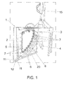
- the actual installing machine consists of a preferably metal support structure, the front part of which has hitching means for its coupling to a tractor vehicle, responsible for pulling it, likewise having at said front part a tip or spike which, like a plow, is driven in the ground and gradually creates a ditch in which the conduit is deposited, which conduit is passed through the mentioned structure through a curved duct.
- This structure which has an approximately quadrangular and planar configuration and which is arranged vertically and perpendicular to the hitch, having means for allowing the introduction of the conduit to be installed already provided with vertical irrigation sections, has the particularity of having a drive chain coupled to a plurality of star bearings, like pinions, facilitating the free sliding of the conduit, making its introduction in the ditch completely friction-free, occurring smoothly and continuously.
- a groove curved at its central part has been provided in the final part of the path of the conduit through the structure, which groove is intended to channel the vertical sections coupled to the conduit and make the latter be suitably placed when the conduit is deposited in the ditch.
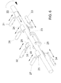
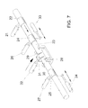
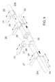
- such machine comprises the use of a plurality of cylinders, electrically actuated by means of corresponding electrovalves, which incorporate, according to the specific function of each one, different actuation elements, the tube being suitably installed in a rotary machine supporting it and making it move forward automatically, the phases of each connection cycle consisting of the steps detailed below:
- a raisable table operated by at least one hydraulic cylinder, being located laterally to said element and in correspondence with the front area of the tractor vehicle, in which table there is established a frame for receiving the T-shaped tubes or connections intended to be intercalated every certain distance in the pipe to be buried.
- the reel provided with the corresponding bushes or bearings, will supply the tube to be buried through the longitudinal guides established in the platform, passing first through the aforementioned cutting machine, such that a user, who will comfortably ride on said platform while the tractor moves at constant speed, will be in charge of handling the cutting and connecting machine for conduits when said vehicle reaches the key points in which said connections are necessary on the ground, such that at the outlet of said machine, the tube with its corresponding connections will move in a rear direction through the longitudinal guide until reaching a second guide, which this time is a curved guide, with a U-shaped section, which directly feeds the apparatus for installing underground irrigation conduits described in invention patent P200802747, the latter carrying out the generation of the corresponding ditch and implantation of the conduit in it.
- the aforementioned machine for installing underground irrigation conduits incorporates in correspondence with its rear end a lance in which two arms are located at the lower part, to which arms a pair of notched disks arranged forming a certain angle between one another, like a wedge, are joined in an articulated manner, through which disks it is possible to cover the furrow again with the conduit already introduced in it, in a completely automatic manner with the earth itself displaced in the process of making said furrow.
- the actual machine for installing underground irrigation conduits may incorporate in it supper area a series of boards or platforms such that in the working situation, the latter are flush with the main platform principal, serving as a support and walkway for the second operator who places the shaft of the sprinklers in correspondence with each "T", without needing to walk on the ground.
- the device will be complemented with a GPS by means of which, and by means of the prior introduction therein of the plans of the plot, said device will indicate the cutting points in which the sprinkler-carrying shaft must be placed, by means of issuing an electric command to the automaton controlling the device, after running by means of wheels over the walkway lateral to the tractor.
- a device is thus achieved with which the time of implantation of the irrigation conduits in the ground is considerably reduced in a virtually automated manner, without risks for the operators.
- an actual apparatus (1) for installing underground irrigation conduits participates in the device of the invention, which apparatus (1) is formed from a metal support structure (2), the front part of which has hitching means (3) for its coupling to a tractor vehicle, responsible for pulling it, as well as a spike (4).
- Said structure (2) has a an approximately quadrangular and planar configuration and is arranged vertically and perpendicular to the hitch (3), incorporating, on one of its sides, a chain (5) coupled to a plurality of star bearings (6), like pinions, which enable and guide the movement thereof, a series of articulated flat bars (7) having been provided distributed along said chain (5), which flat bars have an L-shaped profile, as observed in Figure 5 .
- the mentioned apparatus (1) is complemented with a metal platform (16), in which there is defined an elongated service passage (17), accompanied by the corresponding safety rail (18), parallel to which there is defined a longitudinal guide (19) on which a connecting machine (20) for connecting parts in conduits can move.
- Said machine the one shown in detail in Figures 6 to 12 , comprises a plurality of cylinders, electrically actuated by means of corresponding electrovalves, provided with different actuation elements, the tube being installed in a structure supporting it and making it move forward automatically, the connection process having the following steps:
- the platform (16) will be provided with means for the fixing to the tractor vehicle (36) in question, being finished at the front part in an arm (37) on which a reel (38) is arranged through the corresponding bearings or bushes in a horizontal arrangement, in which the irrigation conduit (23) or tube to be buried in the ground is wound.
- Said conduit (23) will gradually be unwound automatically from the reel (38) to the guide (19), until reaching the connecting machine (20), which will be tended to by an operator, such that said conduit (23) will slide along said machine when it is necessary to perform connections until reaching the rear area of the mentioned longitudinal guide (19) in correspondence with which a second curved guide (39) with a U-shaped section is established, which section allows the sliding through its opening of the branches or connections of the main conduit (23) without the latter being an obstacle for the machine, which second elastic guide (39) will directly feed the apparatus (1) for installing underground irrigation conduits.
- a table (40) is established laterally to the platform (16) in the front area of the same, which table is movable with respect to a lowerable frame (41-41') through a plurality of wheels (42) established on its upper surface, which frame forms a sort of dihedron with a hinging pin (43).
- the table is suitable in shape and size to receive a plurality of connection parts (44) which will be coupled to the main conduit (23) by means of the connecting machine (20), which parts will be taken from said table by the operator when necessary, for which the mentioned lowerable frame (41-41') will have at least one hydraulic cylinder (45) in correspondence with the edge opposite the hinging edge, through which said table can be pivoted, and consequently the content thereof can be made accessible for the operator in question, who will be able to operate comfortably from the platform (16).
- the apparatus (1) for installing underground irrigation conduits it will incorporate in its upper area a lance (46) which in the working situation will be arranged coplanarly with the platform (16), being able to incorporate thereon a series of plates or boards determining additional platforms, not depicted in the figures for the sake of simplicity.
- the device incorporates a pair of arms (47) with a Z-shaped configuration, on the ends of which there are established respective notched and rotating disks (48), arranged obliquely, like a wedge, which allow covering the assembly formed by the installed pipe and the furrow itself with the earth extracted from the furrow.
- a stabilizing element (49) can be inserted in the shaft of the T-shaped connection parts (44)
- which element consists of a cubic body, with a through hole which is suitable in size and shape to allow the passage therethrough of said shaft, which element will be gradually inserted by the operator located on the platform in the "Ts" so that once it is implanted in the furrow, it acts like a stabilizing element preventing said elements from being inclined with the dumping of earth on said furrow, since once they are buried, the correct positioning thereof is much more complicated than carrying out this operation.
Landscapes
- Engineering & Computer Science (AREA)
- General Engineering & Computer Science (AREA)
- Mechanical Engineering (AREA)
- Mining & Mineral Resources (AREA)
- Civil Engineering (AREA)
- Structural Engineering (AREA)
- Life Sciences & Earth Sciences (AREA)
- Soil Sciences (AREA)
- Water Supply & Treatment (AREA)
- Environmental Sciences (AREA)
- Excavating Of Shafts Or Tunnels (AREA)
- Quick-Acting Or Multi-Walled Pipe Joints (AREA)
Applications Claiming Priority (3)
| Application Number | Priority Date | Filing Date | Title |
|---|---|---|---|
| ES200802338A ES2354787B1 (es) | 2008-08-05 | 2008-08-05 | Procedimiento mecanizado para empalme de piezas en conducciones de agua o similar. |
| ES200802747A ES2355026B1 (es) | 2008-09-27 | 2008-09-27 | Aparato instalador de conducciones de riego subterraneas perfeccionado. |
| ES200930336U ES1070771Y (es) | 2009-07-31 | 2009-07-31 | Dispositivo instalador de conducciones de riego subterraneo |
Publications (2)
| Publication Number | Publication Date |
|---|---|
| EP2151525A2 true EP2151525A2 (de) | 2010-02-10 |
| EP2151525A3 EP2151525A3 (de) | 2011-03-23 |
Family
ID=41299922
Family Applications (1)
| Application Number | Title | Priority Date | Filing Date |
|---|---|---|---|
| EP09382135A Withdrawn EP2151525A3 (de) | 2008-08-05 | 2009-08-05 | Vorrichtung zum Anlegen von unterirdischen Bewässerungsrohren und Verfahren zum Anschliessen von Teilen von Bewässerungsrohren |
Country Status (1)
| Country | Link |
|---|---|
| EP (1) | EP2151525A3 (de) |
Cited By (3)
| Publication number | Priority date | Publication date | Assignee | Title |
|---|---|---|---|---|
| EP2354329A1 (de) * | 2010-02-04 | 2011-08-10 | Jordi Sagué Frigolé | Vorrichtung zur Installation von Bewässerungsrohren |
| CN117967870A (zh) * | 2024-03-28 | 2024-05-03 | 内蒙古农业大学 | 一种公共绿地绿化养护装置 |
| IT202300017496A1 (it) * | 2023-08-23 | 2025-02-23 | Damax S R L | Unità stendi-manichette per macchine agricole |
Family Cites Families (2)
| Publication number | Priority date | Publication date | Assignee | Title |
|---|---|---|---|---|
| US2909134A (en) * | 1958-08-25 | 1959-10-20 | Joseph A Kniefel | Machine for laying flexible pipe with attached risers |
| US3631752A (en) * | 1969-12-17 | 1972-01-04 | Northern Natural Gas Co | Subsurface irrigation pipeline device |
-
2009
- 2009-08-05 EP EP09382135A patent/EP2151525A3/de not_active Withdrawn
Cited By (4)
| Publication number | Priority date | Publication date | Assignee | Title |
|---|---|---|---|---|
| EP2354329A1 (de) * | 2010-02-04 | 2011-08-10 | Jordi Sagué Frigolé | Vorrichtung zur Installation von Bewässerungsrohren |
| IT202300017496A1 (it) * | 2023-08-23 | 2025-02-23 | Damax S R L | Unità stendi-manichette per macchine agricole |
| EP4512233A1 (de) * | 2023-08-23 | 2025-02-26 | DAMAX S.r.l. | Schlauchverteilereinheit für landwirtschaftliche maschinen |
| CN117967870A (zh) * | 2024-03-28 | 2024-05-03 | 内蒙古农业大学 | 一种公共绿地绿化养护装置 |
Also Published As
| Publication number | Publication date |
|---|---|
| EP2151525A3 (de) | 2011-03-23 |
Similar Documents
| Publication | Publication Date | Title |
|---|---|---|
| US9010450B2 (en) | Apparatus and methods for facilitating the removal of existing turf and installing new turf | |
| US9938104B2 (en) | Apparatus and methods for facilitating the removal of existing turf and installing new turf | |
| US5913638A (en) | Sand channel trenching and pipe laying apparatus | |
| AU2008204275B2 (en) | Planting of seedlings | |
| EP2151525A2 (de) | Vorrichtung zum Anlegen von unterirdischen Bewässerungsrohren und Verfahren zum Anschliessen von Teilen von Bewässerungsrohren | |
| DE2455759A1 (de) | Pflanzmaschine | |
| CN205660225U (zh) | 一种自动切管机 | |
| WO2018012255A1 (ja) | 林業用ハーベスター | |
| EP2704276B1 (de) | Verfahren zur Verlegung eines Kabels im Offshore-Bereich von einer Windenergieanlage zu einem Zielort und Windenergieanlage zur Anordnung im Offshore-Bereich | |
| US4661018A (en) | Apparatus for and method of installing underground cable having above ground terminals | |
| DE2548338C3 (de) | Verfahren zur Aufnahme von Schnee und gezielten Verteilung desselben auf einer Skipiste sowie Vorrichtung zur Durchführung des Verfahrens | |
| US3395545A (en) | Cable-laying apparatus | |
| US4373833A (en) | Machine for use in implanting plant supporting stakes | |
| EP2354329A1 (de) | Vorrichtung zur Installation von Bewässerungsrohren | |
| EP1634848B1 (de) | Stützvorrichtung für eine Zugvorrichtung zum Verlegen von Rohrleitungen | |
| EP2333164A2 (de) | Vorrichtung zum Vergraben von dünnen Elementen wie Kabeln, Leitungen, Seilen, Ketten, Rohren und dergleichen | |
| US20110142544A1 (en) | Plow apparatus for laying underground cable | |
| ES1072622U (es) | Dispositivo para la instalacion de cañas de riego en campos de regadio. | |
| US4407343A (en) | Tree feller with gravitational buncher | |
| JP6902421B2 (ja) | 作業車両 | |
| JP5521246B2 (ja) | 排水暗渠形成装置 | |
| DE2709474A1 (de) | Verfahren und geraet zur bergarbeit | |
| DE1811504A1 (de) | Verfahren und Vorrichtung zum Abschneiden und Transportieren von Baeumen | |
| DE2840587A1 (de) | Vorrichtung zum verlegen von kabeln, rohren usw. in graeben | |
| EP0123468A1 (de) | Gerät zum Ziehen von Gräben |
Legal Events
| Date | Code | Title | Description |
|---|---|---|---|
| PUAI | Public reference made under article 153(3) epc to a published international application that has entered the european phase |
Free format text: ORIGINAL CODE: 0009012 |
|
| AK | Designated contracting states |
Kind code of ref document: A2 Designated state(s): AT BE BG CH CY CZ DE DK EE ES FI FR GB GR HR HU IE IS IT LI LT LU LV MC MK MT NL NO PL PT RO SE SI SK SM TR |
|
| AX | Request for extension of the european patent |
Extension state: AL BA RS |
|
| PUAL | Search report despatched |
Free format text: ORIGINAL CODE: 0009013 |
|
| AK | Designated contracting states |
Kind code of ref document: A3 Designated state(s): AT BE BG CH CY CZ DE DK EE ES FI FR GB GR HR HU IE IS IT LI LT LU LV MC MK MT NL NO PL PT RO SE SI SK SM TR |
|
| AX | Request for extension of the european patent |
Extension state: AL BA RS |
|
| RIC1 | Information provided on ipc code assigned before grant |
Ipc: A01G 25/06 20060101ALI20110217BHEP Ipc: F16L 1/032 20060101ALI20110217BHEP Ipc: E02B 11/02 20060101AFI20091123BHEP |
|
| STAA | Information on the status of an ep patent application or granted ep patent |
Free format text: STATUS: THE APPLICATION IS DEEMED TO BE WITHDRAWN |
|
| 18D | Application deemed to be withdrawn |
Effective date: 20110924 |