EP2151546A2 - Procédé d'assemblage de turbines ou de compresseurs à plusieurs étages - Google Patents
Procédé d'assemblage de turbines ou de compresseurs à plusieurs étages Download PDFInfo
- Publication number
- EP2151546A2 EP2151546A2 EP09251555A EP09251555A EP2151546A2 EP 2151546 A2 EP2151546 A2 EP 2151546A2 EP 09251555 A EP09251555 A EP 09251555A EP 09251555 A EP09251555 A EP 09251555A EP 2151546 A2 EP2151546 A2 EP 2151546A2
- Authority
- EP
- European Patent Office
- Prior art keywords
- outer casing
- rotor
- rotor drum
- static components
- drum
- Prior art date
- Legal status (The legal status is an assumption and is not a legal conclusion. Google has not performed a legal analysis and makes no representation as to the accuracy of the status listed.)
- Withdrawn
Links
- 238000000034 method Methods 0.000 title claims abstract description 69
- 230000003068 static effect Effects 0.000 claims abstract description 67
- 238000003466 welding Methods 0.000 claims description 4
- 238000003780 insertion Methods 0.000 description 3
- 230000037431 insertion Effects 0.000 description 3
- 238000009434 installation Methods 0.000 description 3
- 238000010276 construction Methods 0.000 description 2
- 238000001816 cooling Methods 0.000 description 2
- 230000013011 mating Effects 0.000 description 2
- 238000012986 modification Methods 0.000 description 2
- 230000004048 modification Effects 0.000 description 2
- 238000011068 loading method Methods 0.000 description 1
- 230000014759 maintenance of location Effects 0.000 description 1
- 238000004519 manufacturing process Methods 0.000 description 1
- 239000000463 material Substances 0.000 description 1
- 239000002184 metal Substances 0.000 description 1
- 230000000717 retained effect Effects 0.000 description 1
- 239000007787 solid Substances 0.000 description 1
Images


Classifications
-
- F—MECHANICAL ENGINEERING; LIGHTING; HEATING; WEAPONS; BLASTING
- F01—MACHINES OR ENGINES IN GENERAL; ENGINE PLANTS IN GENERAL; STEAM ENGINES
- F01D—NON-POSITIVE DISPLACEMENT MACHINES OR ENGINES, e.g. STEAM TURBINES
- F01D25/00—Component parts, details, or accessories, not provided for in, or of interest apart from, other groups
- F01D25/28—Supporting or mounting arrangements, e.g. for turbine casing
- F01D25/285—Temporary support structures, e.g. for testing, assembling, installing, repairing; Assembly methods using such structures
-
- F—MECHANICAL ENGINEERING; LIGHTING; HEATING; WEAPONS; BLASTING
- F01—MACHINES OR ENGINES IN GENERAL; ENGINE PLANTS IN GENERAL; STEAM ENGINES
- F01D—NON-POSITIVE DISPLACEMENT MACHINES OR ENGINES, e.g. STEAM TURBINES
- F01D5/00—Blades; Blade-carrying members; Heating, heat-insulating, cooling or antivibration means on the blades or the members
- F01D5/02—Blade-carrying members, e.g. rotors
- F01D5/06—Rotors for more than one axial stage, e.g. of drum or multiple disc type; Details thereof, e.g. shafts, shaft connections
-
- F—MECHANICAL ENGINEERING; LIGHTING; HEATING; WEAPONS; BLASTING
- F01—MACHINES OR ENGINES IN GENERAL; ENGINE PLANTS IN GENERAL; STEAM ENGINES
- F01D—NON-POSITIVE DISPLACEMENT MACHINES OR ENGINES, e.g. STEAM TURBINES
- F01D5/00—Blades; Blade-carrying members; Heating, heat-insulating, cooling or antivibration means on the blades or the members
- F01D5/30—Fixing blades to rotors; Blade roots ; Blade spacers
- F01D5/3007—Fixing blades to rotors; Blade roots ; Blade spacers of axial insertion type
-
- F—MECHANICAL ENGINEERING; LIGHTING; HEATING; WEAPONS; BLASTING
- F01—MACHINES OR ENGINES IN GENERAL; ENGINE PLANTS IN GENERAL; STEAM ENGINES
- F01D—NON-POSITIVE DISPLACEMENT MACHINES OR ENGINES, e.g. STEAM TURBINES
- F01D9/00—Stators
- F01D9/02—Nozzles; Nozzle boxes; Stator blades; Guide conduits, e.g. individual nozzles
- F01D9/04—Nozzles; Nozzle boxes; Stator blades; Guide conduits, e.g. individual nozzles forming ring or sector
- F01D9/042—Nozzles; Nozzle boxes; Stator blades; Guide conduits, e.g. individual nozzles forming ring or sector fixing blades to stators
-
- F—MECHANICAL ENGINEERING; LIGHTING; HEATING; WEAPONS; BLASTING
- F05—INDEXING SCHEMES RELATING TO ENGINES OR PUMPS IN VARIOUS SUBCLASSES OF CLASSES F01-F04
- F05D—INDEXING SCHEME FOR ASPECTS RELATING TO NON-POSITIVE-DISPLACEMENT MACHINES OR ENGINES, GAS-TURBINES OR JET-PROPULSION PLANTS
- F05D2230/00—Manufacture
- F05D2230/60—Assembly methods
-
- Y—GENERAL TAGGING OF NEW TECHNOLOGICAL DEVELOPMENTS; GENERAL TAGGING OF CROSS-SECTIONAL TECHNOLOGIES SPANNING OVER SEVERAL SECTIONS OF THE IPC; TECHNICAL SUBJECTS COVERED BY FORMER USPC CROSS-REFERENCE ART COLLECTIONS [XRACs] AND DIGESTS
- Y10—TECHNICAL SUBJECTS COVERED BY FORMER USPC
- Y10T—TECHNICAL SUBJECTS COVERED BY FORMER US CLASSIFICATION
- Y10T29/00—Metal working
- Y10T29/49—Method of mechanical manufacture
- Y10T29/49316—Impeller making
- Y10T29/4932—Turbomachine making
- Y10T29/49321—Assembling individual fluid flow interacting members, e.g., blades, vanes, buckets, on rotary support member
-
- Y—GENERAL TAGGING OF NEW TECHNOLOGICAL DEVELOPMENTS; GENERAL TAGGING OF CROSS-SECTIONAL TECHNOLOGIES SPANNING OVER SEVERAL SECTIONS OF THE IPC; TECHNICAL SUBJECTS COVERED BY FORMER USPC CROSS-REFERENCE ART COLLECTIONS [XRACs] AND DIGESTS
- Y10—TECHNICAL SUBJECTS COVERED BY FORMER USPC
- Y10T—TECHNICAL SUBJECTS COVERED BY FORMER US CLASSIFICATION
- Y10T29/00—Metal working
- Y10T29/49—Method of mechanical manufacture
- Y10T29/49316—Impeller making
- Y10T29/4932—Turbomachine making
- Y10T29/49323—Assembling fluid flow directing devices, e.g., stators, diaphragms, nozzles
Definitions
- the present invention relates to a method of assembling a multi-stage turbine or a multi-stage compressor for use in a gas turbine.
- the invention also relates to a gas turbine comprising a multi-stage turbine, or a multi-stage compressor assembled in accordance with the method.
- gas turbine compressors comprise a core rotor which typically comprises between 3 and 12 rotor discs, each carrying a set of radial rotor blades around its periphery.
- the discs are welded or bolted together to form a rotor drum.
- the rotor drum is mounted for rotation within an outer casing, and the casing carries a series of static components, called stator vanes, which are arranged in rows behind respective rows of rotor blades to remove swirl from the flow of air induced through the compressor.
- Each rotor disc and downstream stator row form an individual stage of the compressor.
- Multi-stage turbines have a generally similar construction, with the static components taking the form of nozzle guide vanes (NGVs), as will be known to those of skill in the art.
- NVGs nozzle guide vanes
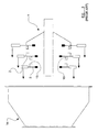
- FIG. 1 illustrates this assembly method in schematic form.
- the rotor drum 1 is initially substantially completely assembled so as to comprise a plurality of spaced-apart rotor discs 2, each having a series of radial rotor blades 3 around its periphery.
- the static components 4 are arranged into rows and secured in positions inside each half 5, 6 of the casing.
- the assembled rotor drum 1 is then lowered into the lower half of the casing 5 such that the rows of rotor blades 3 become inter-digitated with the rows of static components 4 arranged in the lower half of the casing 5.
- the upper half of the casing 6 is then lowered over the assembled rotor drum 1 in order to close the casing and the two halves of the casing are then secured to one another by a plurality of bolts 7 passing through aligned apertures formed in the respective mounting flanges 8, 9.
- this method can be advantageous because it allows the rotor drum 1 to be formed in a single piece, for example by welding together the plurality of rotor discs 2, and thus reduces assembly time relative to a method in which the adjacent rotor discs 2 must themselves be bolted together.
- a single piece rotor drum of this type is also advantageous on aero engines as it has a reduced mass relative to a rotor comprising a series of rotor discs which are bolted to one another.
- the longitudinally split casing design tends to be used mainly on large ground-based power turbines, because in such applications the large physical size of the turbine rotor means that the assembly method is favoured because of its simplicity.
- the problem of ovality can be more easily addressed in a ground-based power turbine by designing the relevant sections of the turbine casing to be oval at room temperature and to become circular at working temperatures. This is not generally possible on an aero engine where the engine must operate efficiently through a wide range of operating temperatures and pressures over the course of a typical flight cycle. Additionally, ground-based power turbines are not subject to the sort of changing thrust and gravitational loadings as an aero engine would be.
- FIG. 1 illustrates a method of assembling a multi-stage turbine.
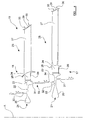
- FIG 2 illustrates this assembly method in schematic form.
- the rotor drum 1 is built-up so as to comprise a plurality of spaced apart rotor discs 2, each having a separate set of rotor blades 3 provided around its periphery.
- Each section of the casing 10, 11, 12 is then added, with its respective static components mounted inside, the casing sections 10, 11, 12 being introduced in sequence, beginning with the largest diameter section 10 corresponding to the largest diameter rotor disc 2.
- Neighbouring casing sections are secured to one another via transverse mounting flanges 13, and bolts 7.
- transversely split casing design illustrated in Figure 2 can be tuned to give very good blade tip clearance because the casing section provided around each stage of the turbine or compressor can be designed so as to expand with the same time-constant as the rotating components of the stage. Also, because each section of the casing takes the form of a complete ring, there is less of a problem with the completed casing ovalising during operation.
- transversely-split casing design can be used for diverging turbines such as that illustrated in Figure 2 (or converging compressors), it lends itself particularly well to the assembly of high pressure turbines of aero engines, because high pressure turbines typically have stages of approximately equal diameter, thereby significantly simplifying the assembly.
- transversely split casing designs can suffer from their own problems. For example they are typically significantly heavier than other turbine/compressor casing designs. This is because the transversely split casings have two sets of flanges and one set of bolts at each stage of the assembly. Also, because of the higher number of component parts which must be joined to one another in order to form the complete casing, tolerance issues can be magnified. Furthermore, due to the large number of additional parts making up the overall assembly, this sort of casing design requires significantly more time to assemble and disassemble.
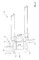
- FIG. 3 Another assembly method, which has been used extensively in the production of low pressure turbine casings used in high by-pass aero engines, is illustrated schematically in Figure 3 , and involves the use of a single-piece, seamless outer casing 14.
- the turbine stages are assembled one at a time, with the static components being fixed inside the casing 14 before each rotor disc 2 is added in turn.
- the smallest rotor disc 2 would be inserted into the outer casing 14, after which the corresponding set of static components would be fixed around the inside of the casing 14.
- the next rotor disc 2 is then inserted into the casing, whereafter the next row of static components are installed within the casing, and so on.
- the rotor drum 1 cannot be of single piece construction (for example made up by welding adjacent rotor discs to each other, and so instead each rotor disc 2 is provided with an annular flange 15 which is arranged to mate with a corresponding annular flange on the adjacent rotor disc, the two flanges being secured to one another by a series of bolts 16.
- the seamless casing design and assembly method illustrated schematically in Figure 3 offers advantages in terms of the weight of the turbine casing 14, whilst also reducing the problem of ovality compared to the longitudinally split casing design, the method and design is not without its own problems.
- the resulting large number of mating flanges 15 and fixing bolts 16 can add significantly to the overall weight of the rotor 1 which can be a particular problem given that this additional weight is provided on a rotating component. It has been calculated that for a large modern aero engine, a low pressure multi-stage turbine built in accordance with this design could have as much as 20 to 50 kg of its total weight made up by the mating flanges 15 and the fixing bolts 16.
- a first aspect of the invention provides a method of assembling a multi-stage compressor or turbine for use in a gas-turbine engine, the method comprising the steps of: i) assembling a rotor drum so as to comprise a plurality of axially arranged rotor discs, ii) releasably connecting a plurality of static components to the assembled rotor drum, to form an intermediate structure, iii) inserting the intermediate structure within an outer casing, iv) fixing the plurality of static components to the outer casing, and v)releasing the static components from the rotor drum to permit rotation of the drum relative to the static components and the outer casing.
- the casing is formed as a unitary component.
- the step of assembling the rotor drum preferably includes the step of welding the rotor discs to one another. Additionally, the step of assembling the rotor drum may include attaching a plurality of rotor blades to at least one of the rotor discs, and at least one of the rotor discs can take the form of an integrally bladed disc.
- each static component is releasably connected to the rotor drum by at least one removable fixing element.
- Each said removable fixing element can be inserted through a respective hole provided in the rotor drum, and may be subsequently removed during said step of releasing the static components from the rotor drum.
- the method may include the further step of closing said holes after removal of said fixing elements.
- the assembly method preferably comprises the step of providing the rotor drum on an assembly mount, with the fixing elements being releasably secured to the assembly mount. At least part of the assembly mount may be provided in a position within the rotor drum, with the fixing elements extending substantially radially outwardly from the mount.
- the rotor drum is actually assembled on the assembly mount, optionally with its rotational axis oriented substantially vertically, and with the rotor drum remaining in said orientation during the step of releasably connecting the static components.
- the step of inserting the intermediate structure within the outer casing comprises lowering the outer casing over the intermediate structure.
- the rotor drum may be assembled with its smallest diameter rotor disc uppermost.
- the method comprises the further step of connecting the rotor drum to a shaft after the step of releasing the static components from the rotor drum.
- Each static component may be provided with a substantially axially extending projection in its radially outermost region, with said step of fixing the static components to the outer casing comprising engaging each said projection in a corresponding slot provided inside the outer casing.
- Each static component may be provided with a substantially radially extending tab at its radially outermost region, and said step of fixing the static components to the outer casing may comprise rotating the outer casing relative to the intermediate structure so that each said radially extending tab becomes radially aligned with a respective inwardly directed tab provided inside the outer casing.
- the step of rotating the outer casing relative to the intermediate structure preferably involves rotation in the same direction to that in which rotational forces will act on the static components (38) relative to the outer casing (50) during operation of the compressor or turbine (i.e. rotation in the same direction to that in which rotational forces will act tending to urge the static components and the casing apart.
- the step of inserting the intermediate structure within the outer casing involves moving each said inwardly directed tab axially past a respective said radially extending tab, prior to said rotation of the outer casing relative to the intermediate structure.
- the outer casing may be provided with inwardly directed abutments, each arranged to abut part of a static component when the radially extending tabs become aligned with respective inwardly directed tabs, thereby defining a limit to the rotation of the outer casing relative to the intermediate structure.
- a gas turbine engine comprising a multi-stage turbine or compressor assembled according to the method outlined above.
- Figure 4 illustrates an early stage in the assembly method of the invention, and shows two adjacent rotor discs 17, 18 which make up part of a turbine rotor drum indicated generally at 19.
- Figure 4 illustrates the adjacent rotor discs 17, 18 in a generally horizontal plane, and shows one half of each disc in cross-section, to the right hand side of the axis of rotation A of the rotor drum 19.
- the rotor drum 19 is preferably assembled in this orientation, with its rotational axis A oriented substantially vertically, and may comprise several adjacent rotor discs.
- the lower of the two rotor discs illustrated has a large diameter relative to the other disc, and during assembly of the rotor drum 19, the drum 19 is oriented such that the smallest rotor disc, forming part of the smallest stage of the turbine, is located uppermost. As will become clear subsequently, this facilitates easier insertion of the assembled rotor drum 19 within the outer casing of the turbine during a subsequent stage of the assembly method.
- Each rotor disc 17, 18 comprises a relatively massive central portion 20, which is commonly known as the cob 20 of the disc.
- the cob 20 surrounds a central aperture 21 by means of which the rotor disc will be fixed to a shaft in the gas turbine engine.
- each disc narrows in a radially outward direction to form a relatively thin web region 22 which carries a blade mounting flange 23.
- the blade mounting flange 23 of each disc is provided with a series of slots around its outer periphery, each slot being configured to receive the root 24 of a respective rotor blade 25.
- the blade roots 24 are illustrated in simplified form in the drawings for the sake of clarity, it will be appreciated that the root 24 will usually have a "fir-tree" configuration for receipt within correspondingly shaped slots, as is conventional.
- Each rotor disc 17, 18 is thus provided with a plurality of radially arranged rotor blades 25, and the blades 25 are retained in position relative to the mounting flange 23 by a generally annular blade retention loop 26, as is also conventional.
- Each rotor blade 25 has an elongate region 27 of aerofoil configuration which extends between a radially innermost blade platform 28 and a radially outermost shroud section 29 at its tip.
- the shroud section of each rotor blade 25 carries a pair of spaced apart shroud tip fins 30.
- each disc has a lower annular flange 31 extending downwardly from the web 20, and an upper annular flange 32 extending upwardly from the web 22, the upper flange 32 being located radially inwardly of the lower flange 31.
- the smaller upper disc 18 is secured to the larger lower disc 17 by way of interconnection between the downwardly extending flange 31 of the upper disc and the upwardly extending flange 32 of the lower disc.
- the inter-connected flanges 31, 32 of the adjacent rotor discs together define an annular drum section 33 extending between the two discs.
- This drum section is provided with a plurality of mounting holes 34 at positions spaced radially around the interconnecting drum section 33.
- the mounting holes 34 are provided in two rows, one of the rows being located generally adjacent the upper rotor disc 18, and the other row of holes being located generally adjacent the lower rotor disc 17.
- the assembled rotor 19 is shown mounted on a generally vertically extending assembly mount 35, the assembly mount having a stepped configuration so as to extend through the axially-aligned central apertures 21 of the rotor discs 17, 18.
- the assembly mount 35 it is preferred that the rotor drum 19 is actually assembled in position on the assembly mount 35.
- a fixing element 36 is inserted through each mounting hole 34 so as to extend radially outwardly from the assembly mount 35, and to terminate with a free end 37 spaced radially outwardly from the respective mounting hole 34.
- Each fixing element 36 preferably takes the form of an elongate metal pin arranged to extend outwardly from the assembly mount 35.
- Each fixing element 36 can thus be mounted for selective radial extension through an appropriate aperture formed in the assembly mount 35.
- each fixing element 36 serves to connect the NGV seals 39 to the assembled rotor drum 19.
- the outermost end 37 of each fixing element 36 is received through a corresponding mounting aperture 40 provided through the inner shroud section 41 of each NGV.
- each of the NGVs illustrated comprises a radially outwardly extending vane 42, of aerofoil configuration, carrying an outer shroud section 43 at its outermost end.
- Each outer shroud section 43 carries an upwardly directed, axially extending projection 44, in the form of a hook, and an outwardly directed, radially extending tab 45.
- the two NGVs 42 are shown interconnected at their radially outermost ends by a seal-segment 46, the seal-segment being arranged to pass around the radially outermost end of the adjacent rotor blade 25.
- the seal-segment 46 is provided with an upturned lip 47 at its lowermost edge, the upturned lip 47 being configured to conform to the inner profile of the recess defined by the hook 44 of the larger diameter NGV.
- the seal segment 46 is provided with an axially directed lip 48 which is arranged to bear against the radially outwardly directed tab 45 of the adjacent smaller diameter NGV, and which carries an outwardly directed convolute seal 49.
- the static components 38 are effectively releasably secured to the assembled rotor drum 19 so that were the rotor drum 19 to be rotated about its vertically oriented axis of rotation A, the static components would all rotate with the drum.
- the combination of the releasably connected static components and the rotary components making up the rotor drum can therefore be considered to represent an intermediate structure.
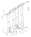
- the intermediate structure formed from the releasably connected static and rotary components is then inserted within an outer casing 50.
- this is effected by lowering the casing 50 over the intermediate structure which is mounted on the vertically oriented assembly mount 35.
- the outer casing 50 is substantially frustoconical in form in order to accommodate the tapering nature of the multi-stage turbine (or compressor) installed within it.
- the outer casing 50 is provided with a series of internal features arranged for connection with the static components of the intermediate structure.
- the outer casing 50 is provided with downwardly directed, axially extending flanges 51, each of which defines a respective axially oriented slot 52 to receive the hooks 44 of each row of NGVs 42.
- the hooks 44 are received within the slots 52 as the outer casing 50 is lowered over the intermediate structure. Engagement of the hooks 44 within the slots 52 serves to restrain the static components 38 in a radial sense.
- the outer casing 50 is also provided with a series of inwardly directed tabs 53, each of which is arranged to cooperate with a respective outwardly directed tab 45.
- the outer casing 50 is lowered over the intermediate structure such that the inwardly directed tabs 53 on the casing are radially offset from the outwardly directed tabs 45 provided on the static components.
- the casing 50 is lowered over the intermediate structure so that the inwardly directed tabs 53 move past the outwardly directed tabs 45, as the hooks 44 become engaged within the slots 52.
- the casing 50 is then rotated relative to the intermediate structure in order to bring the inwardly directed tabs 53 into radial alignment with their respective outwardly directed tabs 45.
- a bayonet-type connection is thus provided between the outer casing and the radially outermost ends of the static components 38.
- the above-mentioned step of rotating the outer casing 50 relative to the intermediate structure involves rotation in the same direction to that in which rotational forces will act on the static components relative to the outer casing during operation of the completed turbine (or compressor).
- each downwardly directed flange 51 provided inside the casing has a small notch 54 formed in its lowermost edge.
- the notch 54 is arranged to receive the uppermost edge of the upturned lip 47 provided on the seal segment 46, thereby securing the seal segment 46 in position as the casing 50 is installed over the intermediate structure.
- the outer casing 50 is provided with a number of inwardly directed abutments 55, as illustrated most clearly in Figure 8 .
- Each abutment 55 is arranged to engage a respective outwardly directed tab 45 on the static component 38, when the tab 45 is radially aligned with a respective inwardly directed tab 53 carried by the casing.
- the abutments 55 are arranged to prevent further rotation of the static components relative to the outer casing 50 in the direction in which the static components will tend to be urged under the flow of gas during operation of the finished turbine (or compressor).
- a number of securing elements 56 may then be inserted through appropriate apertures 57 formed in the outer casing 50.
- the securing elements 56 are each positioned on the opposite side of a respective tab 45 to the adjacent abutment 55 and thus serve to restrain rotation of the static components relative to the outer casing in the opposite direction to that used to make up the bayonet connection.
- the securing elements 56 take the form of pins, or threaded bolts, which may be screwed into the casing 50 from the outside.
- the static components 38 are all fixed to the outer casing 50 at their radially outermost regions.
- Figure 9 illustrates a subsequent stage in the assembly method of the present invention, and shows the static components 38 having been released from their connection to the rotor drum 19 by removal of the fixing elements 36.
- Figure 9 also shows the assembly mount 35 having been removed from the rotor drum 19, whereafter the rotor drum 19 can be mounted on an engine shaft in a generally conventional manner.
- the static components 38 as represented by the nozzle guide vanes 42, are fixed in position relative to the casing 50, whilst the rotor blades 25 and the associated rotor discs 17, 18 are now free to rotate relative to the static components 38 and the outer casing 50.
- the mounting holes 34 provided in the rotor drum 19 could be left open in order to serve a cooling function for the flow of cooling air.
- at least some of the holes 34 could be closed, for example by the insertion of respective plugs 58 as shown in Figure 9 .
Landscapes
- Engineering & Computer Science (AREA)
- Mechanical Engineering (AREA)
- General Engineering & Computer Science (AREA)
- Structures Of Non-Positive Displacement Pumps (AREA)
Applications Claiming Priority (1)
| Application Number | Priority Date | Filing Date | Title |
|---|---|---|---|
| GBGB0814314.1A GB0814314D0 (en) | 2008-08-06 | 2008-08-06 | A Method of assembling a multi-stage turbine or compressor |
Publications (2)
| Publication Number | Publication Date |
|---|---|
| EP2151546A2 true EP2151546A2 (fr) | 2010-02-10 |
| EP2151546A3 EP2151546A3 (fr) | 2017-07-19 |
Family
ID=39767549
Family Applications (1)
| Application Number | Title | Priority Date | Filing Date |
|---|---|---|---|
| EP09251555.0A Withdrawn EP2151546A3 (fr) | 2008-08-06 | 2009-06-13 | Procédé d'assemblage de turbines ou de compresseurs à plusieurs étages |
Country Status (3)
| Country | Link |
|---|---|
| US (1) | US8267646B2 (fr) |
| EP (1) | EP2151546A3 (fr) |
| GB (1) | GB0814314D0 (fr) |
Families Citing this family (8)
| Publication number | Priority date | Publication date | Assignee | Title |
|---|---|---|---|---|
| EP2333245A1 (fr) * | 2009-12-01 | 2011-06-15 | Siemens Aktiengesellschaft | Ensemble de rotor pour turbine à vapeur avec réchauffement |
| EP2706198A1 (fr) * | 2012-09-10 | 2014-03-12 | Alstom Technology Ltd | Procédé pour supprimer un coffrage interne d'une machine |
| CA2903738A1 (fr) | 2013-03-07 | 2014-09-12 | Rolls-Royce Canada, Ltd. | Moteur a turbine a gaz comprenant un systeme d'insertion d'aubes par l'exterieur et methode d'assemblage correspondant |
| CN103591292B (zh) * | 2013-10-23 | 2015-10-28 | 沈阳黎明航空发动机(集团)有限责任公司 | 一种多级外封严环组件组合加工方法 |
| US9969500B2 (en) * | 2014-02-06 | 2018-05-15 | Honeywell International Inc. | Bifurcated ducts including plenums for stabilizing flow therethrough and exhaust systems including the same |
| US10557412B2 (en) * | 2017-05-30 | 2020-02-11 | United Technologies Corporation | Systems for reducing deflection of a shroud that retains fan exit stators |
| CN114193421B (zh) * | 2020-09-02 | 2023-10-13 | 中国航发商用航空发动机有限责任公司 | 转静子单元体的存放架及存放方法 |
| US12247516B2 (en) | 2022-09-29 | 2025-03-11 | General Electric Company | Counter-rotating gas turbine engines including turbine sections with separable torque frames |
Family Cites Families (9)
| Publication number | Priority date | Publication date | Assignee | Title |
|---|---|---|---|---|
| US2972470A (en) * | 1958-11-03 | 1961-02-21 | Gen Motors Corp | Turbine construction |
| GB1047281A (fr) * | 1964-01-23 | |||
| US3628922A (en) * | 1967-02-10 | 1971-12-21 | Sulzer Ag | Method of assembling a pluralstage axial compressor |
| US4016636A (en) * | 1974-07-23 | 1977-04-12 | United Technologies Corporation | Compressor construction |
| SE395174B (sv) * | 1975-08-19 | 1977-08-01 | Stal Laval Turbin Ab | Forfarande for montering av turbomaskin samt verktyg for genomforande av forfarandet |
| US5096375A (en) * | 1989-09-08 | 1992-03-17 | General Electric Company | Radial adjustment mechanism for blade tip clearance control apparatus |
| TR27460A (tr) * | 1990-09-12 | 1995-05-29 | United Technologies Corp | Gaz türbinli motora mahsus kompresör gövdesi yapimi. |
| US6375421B1 (en) * | 2000-01-31 | 2002-04-23 | General Electric Company | Piggyback rotor blisk |
| CN100406684C (zh) * | 2001-11-20 | 2008-07-30 | 阿尔斯通技术有限公司 | 气体涡轮组件 |
-
2008
- 2008-08-06 GB GBGB0814314.1A patent/GB0814314D0/en not_active Ceased
-
2009
- 2009-06-13 EP EP09251555.0A patent/EP2151546A3/fr not_active Withdrawn
- 2009-06-19 US US12/457,750 patent/US8267646B2/en not_active Expired - Fee Related
Also Published As
| Publication number | Publication date |
|---|---|
| US8267646B2 (en) | 2012-09-18 |
| EP2151546A3 (fr) | 2017-07-19 |
| US20100034648A1 (en) | 2010-02-11 |
| GB0814314D0 (en) | 2008-09-10 |
Similar Documents
| Publication | Publication Date | Title |
|---|---|---|
| US8267646B2 (en) | Method of assembling a multi-stage turbine or compressor | |
| EP2369139B1 (fr) | Segment de buse doté d'une bride de poids réduit | |
| US6547518B1 (en) | Low hoop stress turbine frame support | |
| US11085309B2 (en) | Outer drum rotor assembly | |
| CA2652272C (fr) | Turbocompresseur en montage axial | |
| EP3190268A1 (fr) | Aubes de stator variables et agencement d'aubes de stator variables de moteur de turbine à gaz associé | |
| US20170261003A1 (en) | Guide device for variable pitch stator vanes of a turbine engine, and a method of assembling such a device | |
| EP2177714A2 (fr) | Aube mobile pour une section basse pression d'une turbine à vapeur | |
| EP3505726B1 (fr) | Ensemble d'aube pour moteur de turbine à gaz | |
| EP4006314B1 (fr) | Moteur à turbine à gaz | |
| US9376926B2 (en) | Gas turbine engine fan blade lock assembly | |
| EP2984290B1 (fr) | Rotor à aubage intégré | |
| US9957818B2 (en) | Removably attachable snubber assembly | |
| JP5890601B2 (ja) | ターボ機械のロータ組立体とその組立方法 | |
| EP2581559B1 (fr) | Ensemble adaptateur pour accouplement d'aubes de turbine au disque rotor | |
| CN111299993B (zh) | 拆卸涡轮发动机的带有叶片的轮的保持设备及其使用方法 | |
| EP2692995B1 (fr) | Moteur à turbine à gaz stationnaire et procédé pour effectuer les travaux de maintenance | |
| CN105229262A (zh) | 叶片系统和制造叶片系统的对应方法 | |
| GB2434414A (en) | Stator blade assembly | |
| EP2634375A2 (fr) | Joints pour un moteur à turbine, agencement de moteur à turbine et procédé de fabrication associé | |
| EP3693546B1 (fr) | Profil aérodynamique comportant une cavité fermée d'extrémité et agencement de noyau associé | |
| EP3228856B1 (fr) | Élément de retrait de pale de soufflante pour moteur à turbine à gaz et méthode associée | |
| US10738638B2 (en) | Rotor blade with wheel space swirlers and method for forming a rotor blade with wheel space swirlers | |
| US11655719B2 (en) | Airfoil assembly | |
| US12012857B2 (en) | Platform for an airfoil of a gas turbine engine |
Legal Events
| Date | Code | Title | Description |
|---|---|---|---|
| PUAI | Public reference made under article 153(3) epc to a published international application that has entered the european phase |
Free format text: ORIGINAL CODE: 0009012 |
|
| AK | Designated contracting states |
Kind code of ref document: A2 Designated state(s): AT BE BG CH CY CZ DE DK EE ES FI FR GB GR HR HU IE IS IT LI LT LU LV MC MK MT NL NO PL PT RO SE SI SK TR |
|
| AX | Request for extension of the european patent |
Extension state: AL BA RS |
|
| RAP1 | Party data changed (applicant data changed or rights of an application transferred) |
Owner name: ROLLS-ROYCE PLC |
|
| PUAL | Search report despatched |
Free format text: ORIGINAL CODE: 0009013 |
|
| AK | Designated contracting states |
Kind code of ref document: A3 Designated state(s): AT BE BG CH CY CZ DE DK EE ES FI FR GB GR HR HU IE IS IT LI LT LU LV MC MK MT NL NO PL PT RO SE SI SK TR |
|
| AX | Request for extension of the european patent |
Extension state: AL BA RS |
|
| RIC1 | Information provided on ipc code assigned before grant |
Ipc: F01D 5/06 20060101ALI20170615BHEP Ipc: F01D 5/30 20060101ALI20170615BHEP Ipc: F01D 25/28 20060101ALI20170615BHEP Ipc: F01D 9/04 20060101ALI20170615BHEP Ipc: F01D 25/24 20060101AFI20170615BHEP |
|
| STAA | Information on the status of an ep patent application or granted ep patent |
Free format text: STATUS: THE APPLICATION HAS BEEN PUBLISHED |
|
| STAA | Information on the status of an ep patent application or granted ep patent |
Free format text: STATUS: THE APPLICATION IS DEEMED TO BE WITHDRAWN |
|
| 18D | Application deemed to be withdrawn |
Effective date: 20180120 |