EP2151597B1 - Frein à disques pouvant être actionné de manière pneumatique ou électropneumatique - Google Patents
Frein à disques pouvant être actionné de manière pneumatique ou électropneumatique Download PDFInfo
- Publication number
- EP2151597B1 EP2151597B1 EP09010208.8A EP09010208A EP2151597B1 EP 2151597 B1 EP2151597 B1 EP 2151597B1 EP 09010208 A EP09010208 A EP 09010208A EP 2151597 B1 EP2151597 B1 EP 2151597B1
- Authority
- EP
- European Patent Office
- Prior art keywords
- brake
- disc
- drive
- clutch
- disc brake
- Prior art date
- Legal status (The legal status is an assumption and is not a legal conclusion. Google has not performed a legal analysis and makes no representation as to the accuracy of the status listed.)
- Active
Links
- 238000006073 displacement reaction Methods 0.000 claims description 3
- 238000003825 pressing Methods 0.000 claims description 3
- 230000001360 synchronised effect Effects 0.000 claims description 3
- 230000008878 coupling Effects 0.000 description 13
- 238000010168 coupling process Methods 0.000 description 13
- 238000005859 coupling reaction Methods 0.000 description 13
- 230000033001 locomotion Effects 0.000 description 13
- 230000005540 biological transmission Effects 0.000 description 3
- 230000007246 mechanism Effects 0.000 description 3
- 230000000903 blocking effect Effects 0.000 description 2
- 238000009434 installation Methods 0.000 description 2
- 230000009467 reduction Effects 0.000 description 2
- 239000013585 weight reducing agent Substances 0.000 description 2
- 230000009471 action Effects 0.000 description 1
- 230000015572 biosynthetic process Effects 0.000 description 1
- 230000008859 change Effects 0.000 description 1
- 238000010276 construction Methods 0.000 description 1
- 230000001419 dependent effect Effects 0.000 description 1
- 239000002783 friction material Substances 0.000 description 1
- 239000000446 fuel Substances 0.000 description 1
- 230000000977 initiatory effect Effects 0.000 description 1
- 230000007774 longterm Effects 0.000 description 1
- 238000004519 manufacturing process Methods 0.000 description 1
- 239000002184 metal Substances 0.000 description 1
- 238000000034 method Methods 0.000 description 1
- 238000005457 optimization Methods 0.000 description 1
- 230000008569 process Effects 0.000 description 1
- 230000004044 response Effects 0.000 description 1
Images



Classifications
-
- F—MECHANICAL ENGINEERING; LIGHTING; HEATING; WEAPONS; BLASTING
- F16—ENGINEERING ELEMENTS AND UNITS; GENERAL MEASURES FOR PRODUCING AND MAINTAINING EFFECTIVE FUNCTIONING OF MACHINES OR INSTALLATIONS; THERMAL INSULATION IN GENERAL
- F16D—COUPLINGS FOR TRANSMITTING ROTATION; CLUTCHES; BRAKES
- F16D65/00—Parts or details
- F16D65/38—Slack adjusters
- F16D65/40—Slack adjusters mechanical
- F16D65/52—Slack adjusters mechanical self-acting in one direction for adjusting excessive play
- F16D65/56—Slack adjusters mechanical self-acting in one direction for adjusting excessive play with screw-thread and nut
- F16D65/567—Slack adjusters mechanical self-acting in one direction for adjusting excessive play with screw-thread and nut for mounting on a disc brake
- F16D65/568—Slack adjusters mechanical self-acting in one direction for adjusting excessive play with screw-thread and nut for mounting on a disc brake for synchronous adjustment of actuators arranged in parallel
-
- F—MECHANICAL ENGINEERING; LIGHTING; HEATING; WEAPONS; BLASTING
- F16—ENGINEERING ELEMENTS AND UNITS; GENERAL MEASURES FOR PRODUCING AND MAINTAINING EFFECTIVE FUNCTIONING OF MACHINES OR INSTALLATIONS; THERMAL INSULATION IN GENERAL
- F16D—COUPLINGS FOR TRANSMITTING ROTATION; CLUTCHES; BRAKES
- F16D65/00—Parts or details
- F16D65/38—Slack adjusters
- F16D65/40—Slack adjusters mechanical
- F16D65/52—Slack adjusters mechanical self-acting in one direction for adjusting excessive play
- F16D65/56—Slack adjusters mechanical self-acting in one direction for adjusting excessive play with screw-thread and nut
- F16D65/567—Slack adjusters mechanical self-acting in one direction for adjusting excessive play with screw-thread and nut for mounting on a disc brake
Definitions
- the invention relates to a pneumatically or electromechanically operable disc brake according to the preamble of claim 1.
- Such disc brakes need to generate the required application force a mechanical translation, since the force of the particular pneumatically actuated brake cylinder is limited due to the pressure level (currently about 10 bar) and the limited size of the brake cylinder.
- the friction material thickness of the brake pads is about 20 mm. Since two coverings are installed, this results in a wear path of about 40 mm, without taking the brake disc wear into account. This way is many times larger than the o.g. Brake application. There is therefore a need to adjust the brake by means of a device according to the pad wear.
- the prior art is an automatically working wear adjustment, which is achieved so that the so-called clearance, which means the gap between the brake pads and the brake disc in the unactuated state, regardless is kept constant by the wear state and wear behavior of the brake pads.
- concentric adjusters are arranged in the adjusting spindles formed as threaded tubes, one of which is arranged via a drive element, e.g. a shift finger or a gear, is driven by a brake lever.
- the brake lever coupled to a piston rod of the brake cylinder executes a pivoting movement.
- the known adjusting devices are placed in the interior of the adjusting spindles, wherein usually only one adjusting device is actuated via the brake lever, while for synchronous adjustment of the other adjusting spindle transmission means are provided with which a same adjustment of both adjusting spindles is ensured.
- the invention has for its object to further develop a disc brake of the generic type so that it can be made smaller while retaining proven construction or functional principles of the adjusting device.
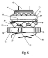
- the space-consuming functional parts ie the ball cone clutch, the ball ramp clutch, the driven pulley and the biasing spring are arranged in the brake caliper outside the overlap region of the brake lever, while the so-called leaner components, such as the axis of rotation and guided thereon drive sleeve are guided by the brake caliper to this Purpose preferably has a recess.
- the invention leads to a weight reduction of the disc brake as a whole and to a reduction in space. Both correspond to the demands made on an optimization of the disc brake, wherein especially the weight reduction leads to a reduction of the fuel consumption of the vehicle.
- the central drive element of the adjusting device may be formed as a gear corresponding to corresponding gears of the adjusting spindles. These gear parts are to produce as simple sheet metal parts.
- the power shift clutch consisting of the ball cone clutch and thus a structural unit forming ball ramp clutch is precisely adjustable, as the Switching force is defined exclusively by the geometric shape of the ramps and by the adjustable biasing spring.
- a manual reset of the adjusting device is possible with only a small amount of force because the said power shift clutch does not have to be overcome.
- FIG. 1 is a part of a pneumatically or electromechanically actuated disc brake, in particular for a commercial vehicle, with a caliper 1, arranged therein, a brake lever 2 having Zuspann issued for pressing brake pads, not shown, to a brake disc, wherein two parallel and spaced apart adjusting spindles 5 means of the brake lever 2 can be pressed under axial displacement against the associated brake pad.
- an adjustable by the brake lever 2 adjusting device 3 is arranged, with the axial displacement of the adjusting spindles 5 a wear-related change of a clearance between the brake pad and the brake disc is substantially compensated.
- the adjusting device 3 is arranged between the adjusting spindles 5 and is operatively connected to these via a gear.
- This transmission consists of a central drive element 7 in the form of a gear which is secured against rotation with a drive sleeve 10 (FIG. FIG. 2 ) is connected and which corresponds to two gear wheels 6 also designed as gears, which are each attached to the adjusting spindles 5.
- the brake lever 2 Upon actuation of the brake, the brake lever 2 performs a pivoting movement, which is guided via a drive wheel 4 in the adjusting device 3 and transmitted to the drive sleeve 10.
- this drive sleeve 10 is a tapered bush 14 of a ball cone clutch 13 ( FIG. 4 ), while a coupling ring 15 of the ball cone clutch 13 is frictionally engaged with a ball ramp clutch 17 in contact.
- the adjusting device 3 has a power shift clutch, which is formed by the mentioned ball cone clutch 13 and ball ramp clutch 17.
- balls 26 of the ball ramp clutch 17 associated ramps 27 roll on the coupling ring 15 and the driven pulley 18, which is pressed down against the force of a biasing spring 20, which abuts with its other end a spring plate 21 is supported, which is fixed to the axis of rotation 9.
- the adjusting device 3 To replace wear-related brake linings, the adjusting device 3 must be reset manually, which takes place by turning on a via a thrust bearing 12 on the drive sleeve 10 supporting the reverse rotation element 11 with counter to the blocking effect of the freewheel. For this purpose, it is therefore necessary to remove the blocking effect of the freewheel.
- a directional coupling acting in the axial direction is provided, the component of which is the coupling ring 15, which is coupled in a rotationally fixed manner to the axis of rotation 9 by means of splines 22.
- the coupling of the axis of rotation 9 with the coupling ring 15 causes the rotational axis 9 corresponding to the pivot angle of the brake lever 2 is rotated during each brake operation.
- the state of wear of the brake pads can be detected, since the axis of rotation 9 in addition to an oscillating, the brake lever analog movement, also executes the adjustment angle corresponding rotary motion.
Landscapes
- Engineering & Computer Science (AREA)
- General Engineering & Computer Science (AREA)
- Mechanical Engineering (AREA)
- Braking Arrangements (AREA)
Claims (12)
- Frein à disque pouvant être actionné pneumatiquement ou électromécaniquement, notamment pour un véhicule utilitaire, comprenanta) un étrier (1) de frein recouvrant un disque de frein,b) un dispositif de serrage monté dans l'étrier (1) de frein, ayant un levier (2) de frein et destiné à presser des garnitures de frein sur le disque de frein,c) deux broches (5) de réglage, qui sont disposées parallèlement et à distance l'une de l'autre et qui peuvent être déplacées axialement à l'aide du dispositif de serrage,d) un dispositif (3) de réglage, qui est placé dans l'étrier de frein, qui peut être actionné par le levier (2) de frein et par lequel, par un réglage axial des broches (5) de réglage, une modification due à l'usure d'un jeu d'air entre la garniture de frein et le disque de frein peut être compensée sensiblement,e) un dispositif (3) de réglage ayant un élément (7) central d'entraînement, qui est disposé entre les broches (5) de réglage et qui est en liaison d'action avec celles-ci par une transmission, l'élément (7) central d'entraînement étant en liaison d'action pour le réglage en synchronisme avec des roues (6) de transmission fixées respectivement sur une broche (5) de réglage,caractérisé en ce que l'élément (7) d'entraînement a un embrayage de commande en charge constitué d'un embrayage (13) conique à billes et d'un embrayage (17) à rampe à billes formant ainsi une unité de construction et soumis à l'action d'un ressort au moyen d'un ressort (20) réglable de précontrainte, l'embrayage (13) conique à billes ayant une douille (14) conique guidée sur un axe (9) de rotation et à évidement en forme de calotte du côté de son cône, sur lesquels pénètrent des billes qui s'appuient, d'autre part, sur une bague (15) d'embrayage commune avec l'embrayage (17) à rampe à billes, et l'élément (7) d'entraînement est en prise avec un disque (18) de sortie, qui fait partie de l'embrayage (17) à rampe à billes.
- Frein à disque suivant la revendication 1, caractérisé en ce que l'élément (7) d'entraînement est constitué en roue dentée.
- Frein à disque suivant la revendication 1 ou 2, caractérisé en ce que le dispositif (3) de réglage a un axe (9) de rotation, ainsi qu'une douille (10) d'entraînement qui y est guidée et à laquelle est raccordée une roue (4) d'entraînement en liaison avec le levier (2) de rotation.
- Frein à disque suivant l'une des revendications précédentes, caractérisé en ce que le disque (18) de sortie a, sur le pourtour extérieur, des dents (19), qui pénètrent dans des vides (28) de l'élément (7) d'entraînement.
- Frein à disque suivant l'une des revendications précédentes, caractérisé en ce que le disque (18) de sortie peut tourner librement d'une valeur angulaire par rapport à l'élément (7) d'entraînement.
- Frein à disque suivant l'une des revendications précédentes, caractérisé en ce que la bague (15) d'embrayage est reliée à l'axe (9) d'entraînement par une denture cunéiforme.
- Frein à disque suivant l'une des revendications précédentes, caractérisé en ce que, du côté éloigné de l'embrayage (13) conique à billes, est monté un palier (24) de butée, sur lequel s'appuient, d'une part, le disque (18) de sortie et, d'autre part, un ressort (20) de précontrainte, qui s'applique à une coupelle (21) de ressort fixée à l'axe (9) de rotation.
- Frein à disque suivant l'une des revendications précédentes, caractérisé en ce que l'axe (9) de rotation et la douille (10) d'entraînement sont guidés dans un évidement (8) du levier (2) de frein.
- Frein à disque suivant l'une des revendications précédentes, caractérisé en ce que l'unité de construction embrayage (13) conique à billes/embrayage (17) à rampe à billes/ palier (24) de butée/ressort (20) de précontrainte/élément (7) d'entraînement est placée dans l'étrier de frein à l'extérieur du levier (2) de frein.
- Frein à disque suivant l'une des revendications précédentes, caractérisé en ce que le dispositif (3) de réglage est pourvu, sur sa partie d'extrémité opposée au ressort (20) de précontrainte, d'un élément (11) de rappel de rotation ayant une protection vis-à-vis d'une surcharge.
- Frein à disque suivant l'une des revendications précédentes, caractérisé en ce qu'un ressort (16) de torsion est en prise avec la bague (15) d'embrayage.
- Frein à disque suivant l'une des revendications précédentes, caractérisé en ce que, sur la douille (10) d'entraînement, est fixée une roue (4) d'entraînement, qui est en prise avec un groupe d'entraînement du levier (2) de frein pour faire tourner la douille (10) d'entraînement lors du pivotement du levier (2) de frein.
Applications Claiming Priority (1)
| Application Number | Priority Date | Filing Date | Title |
|---|---|---|---|
| DE200810036765 DE102008036765A1 (de) | 2008-08-07 | 2008-08-07 | Pneumatisch oder elektromechanisch betätigbare Scheibenbremse |
Publications (2)
| Publication Number | Publication Date |
|---|---|
| EP2151597A1 EP2151597A1 (fr) | 2010-02-10 |
| EP2151597B1 true EP2151597B1 (fr) | 2014-03-05 |
Family
ID=41226832
Family Applications (1)
| Application Number | Title | Priority Date | Filing Date |
|---|---|---|---|
| EP09010208.8A Active EP2151597B1 (fr) | 2008-08-07 | 2009-08-07 | Frein à disques pouvant être actionné de manière pneumatique ou électropneumatique |
Country Status (3)
| Country | Link |
|---|---|
| EP (1) | EP2151597B1 (fr) |
| DE (1) | DE102008036765A1 (fr) |
| ES (1) | ES2463998T3 (fr) |
Cited By (1)
| Publication number | Priority date | Publication date | Assignee | Title |
|---|---|---|---|---|
| US10570970B2 (en) | 2015-09-01 | 2020-02-25 | Knorr-Bremse Systeme Fuer Nutzfahrzeuge Gmbh | Disc brake for a commercial vehicle |
Families Citing this family (13)
| Publication number | Priority date | Publication date | Assignee | Title |
|---|---|---|---|---|
| DE102008035366A1 (de) * | 2008-07-30 | 2010-02-04 | Knorr-Bremse Systeme für Nutzfahrzeuge GmbH | Nachstellvorrichtung für eine Scheibenbremse |
| DE102009033394A1 (de) | 2009-07-16 | 2011-01-27 | Knorr-Bremse Systeme für Nutzfahrzeuge GmbH | Pneumatisch oder elektromechanisch betätigbare Scheibenbremse |
| DE102010024062B4 (de) | 2010-06-17 | 2017-02-02 | Knorr-Bremse Systeme für Nutzfahrzeuge GmbH | Scheibenbremse für ein Nutzfahrzeug |
| DE102010026076B4 (de) | 2010-07-05 | 2015-06-11 | Knorr-Bremse Systeme für Nutzfahrzeuge GmbH | Scheibenbremse für ein Nutzfahrzeug |
| DE102012008573B4 (de) * | 2012-04-27 | 2016-05-12 | Knorr-Bremse Systeme für Nutzfahrzeuge GmbH | Scheibenbremse für ein Nutzfahrzeug |
| DE102012108672B3 (de) | 2012-09-17 | 2014-02-06 | Knorr-Bremse Systeme für Nutzfahrzeuge GmbH | Nachstelleinrichtung einer Scheibenbremse, eine entsprechende Scheibenbremse und Verfahren zum Betreiben einer Verschleißnachstellvorrichtung einer Scheibenbremse |
| DE102014111229B4 (de) | 2014-08-07 | 2019-05-16 | Knorr-Bremse Systeme für Nutzfahrzeuge GmbH | Scheibenbremse für ein Nutzfahrzeug |
| DE102014111228B4 (de) | 2014-08-07 | 2016-11-10 | Knorr-Bremse Systeme für Nutzfahrzeuge GmbH | Scheibenbremse für ein Nutzfahrzeug |
| DE102014019111B4 (de) | 2014-12-19 | 2016-07-21 | Knorr-Bremse Systeme für Nutzfahrzeuge GmbH | Scheibenbremse für ein Nutzfahrzeug |
| DE102015101298B4 (de) | 2015-01-29 | 2022-06-02 | Knorr-Bremse Systeme für Nutzfahrzeuge GmbH | Scheibenbremse für ein Nutzfahrzeug |
| DE102015103612A1 (de) | 2015-03-12 | 2016-09-15 | Knorr-Bremse Systeme für Nutzfahrzeuge GmbH | Scheibenbremse für ein Nutzfahrzeug |
| DE102015114111B4 (de) | 2015-08-26 | 2021-02-18 | Knorr-Bremse Systeme für Nutzfahrzeuge GmbH | Scheibenbremse für ein Nutzfahrzeug |
| DE102017125867B4 (de) | 2017-11-06 | 2022-05-25 | Knorr-Bremse Systeme für Nutzfahrzeuge GmbH | Nachstelleinrichtung einer Scheibenbremse |
Citations (1)
| Publication number | Priority date | Publication date | Assignee | Title |
|---|---|---|---|---|
| DE4034165A1 (de) * | 1990-06-07 | 1991-12-12 | Knorr Bremse Ag | Scheibenbremse fuer fahrzeuge |
Family Cites Families (5)
| Publication number | Priority date | Publication date | Assignee | Title |
|---|---|---|---|---|
| DE4334914A1 (de) | 1993-10-13 | 1995-04-20 | Knorr Bremse Systeme | Druckluftbetätigte Scheibenbremse |
| GB9526019D0 (en) * | 1995-12-20 | 1996-02-21 | Lucas Ind Plc | Improvements relating to disc brake construction |
| GB9716363D0 (en) * | 1997-08-02 | 1997-10-08 | Lucas Ind Plc | Improvements relating to disc brakes |
| DE102004019723B4 (de) * | 2004-04-20 | 2007-11-29 | Knorr-Bremse Systeme für Nutzfahrzeuge GmbH | Nachstellvorrichtung für pneumatisch betätigte Scheibenbremsen und Scheibenbremse |
| DE102004037771A1 (de) | 2004-08-04 | 2006-03-16 | Knorr-Bremse Systeme für Nutzfahrzeuge GmbH | Nachstellvorrichtung für eine pneumatisch betätigte Scheibenbremse |
-
2008
- 2008-08-07 DE DE200810036765 patent/DE102008036765A1/de not_active Ceased
-
2009
- 2009-08-07 EP EP09010208.8A patent/EP2151597B1/fr active Active
- 2009-08-07 ES ES09010208.8T patent/ES2463998T3/es active Active
Patent Citations (1)
| Publication number | Priority date | Publication date | Assignee | Title |
|---|---|---|---|---|
| DE4034165A1 (de) * | 1990-06-07 | 1991-12-12 | Knorr Bremse Ag | Scheibenbremse fuer fahrzeuge |
Cited By (1)
| Publication number | Priority date | Publication date | Assignee | Title |
|---|---|---|---|---|
| US10570970B2 (en) | 2015-09-01 | 2020-02-25 | Knorr-Bremse Systeme Fuer Nutzfahrzeuge Gmbh | Disc brake for a commercial vehicle |
Also Published As
| Publication number | Publication date |
|---|---|
| EP2151597A1 (fr) | 2010-02-10 |
| ES2463998T3 (es) | 2014-05-29 |
| DE102008036765A1 (de) | 2010-02-11 |
Similar Documents
| Publication | Publication Date | Title |
|---|---|---|
| EP2151597B1 (fr) | Frein à disques pouvant être actionné de manière pneumatique ou électropneumatique | |
| EP2307756B1 (fr) | Dispositif de rattrapage de jeu pour un frein à disque | |
| EP2222977B1 (fr) | Frein à friction électromécanique | |
| EP1776531B1 (fr) | Dispositif de reglage pour un frein a disque a actionnement pneumatique | |
| DE3716202C2 (de) | Scheibenbremse für Fahrzeuge | |
| EP2069655B1 (fr) | Frein combine pour vehicule presentant un frein de stationnement actionnable de maniere electromecanique, et transmission pour la transformation d'un mouvement de rotation en un mouvement de translation | |
| DE19729024C1 (de) | Verschleißnachstellvorrichtung für Scheibenbremsen | |
| EP0478917B1 (fr) | Dispositif de rattrapage automatique de jeu pour un frein à disque à étrier flottant à commande mécanique | |
| EP2318730B1 (fr) | Dispositif d'ajustement pour frein à disque | |
| EP2307755B1 (fr) | Dispositif d'ajustement pour frein à disque | |
| EP1386092B1 (fr) | Frein a disque comprenant un systeme de reglage d'usure a entrainement electromotorise | |
| DE3229052C2 (fr) | ||
| EP1646798A1 (fr) | Actionneur d'embrayage | |
| DE2354322C2 (de) | Hydraulisch und mechanisch wirkende Bremsbetätigungsvorrichtung | |
| EP2088355B1 (fr) | Dispositif d'actionnement pour une soupape ou une armature | |
| EP1877679B1 (fr) | Dispositif de rattrapage de jeu pour un frein a disque a commande pneumatique | |
| EP2636917B1 (fr) | Dispositif de réglage d'usure pour freins à disques | |
| EP3423729A1 (fr) | Actionneur électromécanique pour actionner un système à transmission de force par liaison par friction | |
| DE102008028265B4 (de) | Nachstellvorrichtung für eine Scheibenbremse | |
| DE19902708B4 (de) | Betätigungsvorrichtung für eine Bremse | |
| EP3867544B1 (fr) | Frein à disque | |
| WO2007057464A1 (fr) | Frein electromecanique pour vehicules comprenant un dispositif compensant l'usure du revetement de friction | |
| DE102016013849A1 (de) | Nachstellvorrichtung für eine Scheibenbremse | |
| DE3814475A1 (de) | Mechanisch betaetigte gleitsattel-scheibenbremse |
Legal Events
| Date | Code | Title | Description |
|---|---|---|---|
| PUAI | Public reference made under article 153(3) epc to a published international application that has entered the european phase |
Free format text: ORIGINAL CODE: 0009012 |
|
| AK | Designated contracting states |
Kind code of ref document: A1 Designated state(s): AT BE BG CH CY CZ DE DK EE ES FI FR GB GR HR HU IE IS IT LI LT LU LV MC MK MT NL NO PL PT RO SE SI SK SM TR |
|
| AX | Request for extension of the european patent |
Extension state: AL BA RS |
|
| 17P | Request for examination filed |
Effective date: 20100810 |
|
| 17Q | First examination report despatched |
Effective date: 20100830 |
|
| GRAP | Despatch of communication of intention to grant a patent |
Free format text: ORIGINAL CODE: EPIDOSNIGR1 |
|
| INTG | Intention to grant announced |
Effective date: 20130918 |
|
| GRAS | Grant fee paid |
Free format text: ORIGINAL CODE: EPIDOSNIGR3 |
|
| GRAA | (expected) grant |
Free format text: ORIGINAL CODE: 0009210 |
|
| AK | Designated contracting states |
Kind code of ref document: B1 Designated state(s): AT BE BG CH CY CZ DE DK EE ES FI FR GB GR HR HU IE IS IT LI LT LU LV MC MK MT NL NO PL PT RO SE SI SK SM TR |
|
| REG | Reference to a national code |
Ref country code: GB Ref legal event code: FG4D Free format text: NOT ENGLISH |
|
| REG | Reference to a national code |
Ref country code: CH Ref legal event code: EP |
|
| REG | Reference to a national code |
Ref country code: AT Ref legal event code: REF Ref document number: 655094 Country of ref document: AT Kind code of ref document: T Effective date: 20140315 |
|
| REG | Reference to a national code |
Ref country code: IE Ref legal event code: FG4D Free format text: LANGUAGE OF EP DOCUMENT: GERMAN |
|
| REG | Reference to a national code |
Ref country code: DE Ref legal event code: R096 Ref document number: 502009008898 Country of ref document: DE Effective date: 20140417 |
|
| REG | Reference to a national code |
Ref country code: ES Ref legal event code: FG2A Ref document number: 2463998 Country of ref document: ES Kind code of ref document: T3 Effective date: 20140529 |
|
| REG | Reference to a national code |
Ref country code: SE Ref legal event code: TRGR |
|
| REG | Reference to a national code |
Ref country code: NL Ref legal event code: VDEP Effective date: 20140305 |
|
| PG25 | Lapsed in a contracting state [announced via postgrant information from national office to epo] |
Ref country code: NO Free format text: LAPSE BECAUSE OF FAILURE TO SUBMIT A TRANSLATION OF THE DESCRIPTION OR TO PAY THE FEE WITHIN THE PRESCRIBED TIME-LIMIT Effective date: 20140605 Ref country code: LT Free format text: LAPSE BECAUSE OF FAILURE TO SUBMIT A TRANSLATION OF THE DESCRIPTION OR TO PAY THE FEE WITHIN THE PRESCRIBED TIME-LIMIT Effective date: 20140305 |
|
| REG | Reference to a national code |
Ref country code: LT Ref legal event code: MG4D |
|
| PG25 | Lapsed in a contracting state [announced via postgrant information from national office to epo] |
Ref country code: CY Free format text: LAPSE BECAUSE OF FAILURE TO SUBMIT A TRANSLATION OF THE DESCRIPTION OR TO PAY THE FEE WITHIN THE PRESCRIBED TIME-LIMIT Effective date: 20140305 Ref country code: FI Free format text: LAPSE BECAUSE OF FAILURE TO SUBMIT A TRANSLATION OF THE DESCRIPTION OR TO PAY THE FEE WITHIN THE PRESCRIBED TIME-LIMIT Effective date: 20140305 |
|
| PG25 | Lapsed in a contracting state [announced via postgrant information from national office to epo] |
Ref country code: HR Free format text: LAPSE BECAUSE OF FAILURE TO SUBMIT A TRANSLATION OF THE DESCRIPTION OR TO PAY THE FEE WITHIN THE PRESCRIBED TIME-LIMIT Effective date: 20140305 Ref country code: LV Free format text: LAPSE BECAUSE OF FAILURE TO SUBMIT A TRANSLATION OF THE DESCRIPTION OR TO PAY THE FEE WITHIN THE PRESCRIBED TIME-LIMIT Effective date: 20140305 |
|
| PG25 | Lapsed in a contracting state [announced via postgrant information from national office to epo] |
Ref country code: RO Free format text: LAPSE BECAUSE OF FAILURE TO SUBMIT A TRANSLATION OF THE DESCRIPTION OR TO PAY THE FEE WITHIN THE PRESCRIBED TIME-LIMIT Effective date: 20140305 Ref country code: NL Free format text: LAPSE BECAUSE OF FAILURE TO SUBMIT A TRANSLATION OF THE DESCRIPTION OR TO PAY THE FEE WITHIN THE PRESCRIBED TIME-LIMIT Effective date: 20140305 Ref country code: IS Free format text: LAPSE BECAUSE OF FAILURE TO SUBMIT A TRANSLATION OF THE DESCRIPTION OR TO PAY THE FEE WITHIN THE PRESCRIBED TIME-LIMIT Effective date: 20140705 Ref country code: CZ Free format text: LAPSE BECAUSE OF FAILURE TO SUBMIT A TRANSLATION OF THE DESCRIPTION OR TO PAY THE FEE WITHIN THE PRESCRIBED TIME-LIMIT Effective date: 20140305 Ref country code: BG Free format text: LAPSE BECAUSE OF FAILURE TO SUBMIT A TRANSLATION OF THE DESCRIPTION OR TO PAY THE FEE WITHIN THE PRESCRIBED TIME-LIMIT Effective date: 20140605 Ref country code: EE Free format text: LAPSE BECAUSE OF FAILURE TO SUBMIT A TRANSLATION OF THE DESCRIPTION OR TO PAY THE FEE WITHIN THE PRESCRIBED TIME-LIMIT Effective date: 20140305 |
|
| PG25 | Lapsed in a contracting state [announced via postgrant information from national office to epo] |
Ref country code: PL Free format text: LAPSE BECAUSE OF FAILURE TO SUBMIT A TRANSLATION OF THE DESCRIPTION OR TO PAY THE FEE WITHIN THE PRESCRIBED TIME-LIMIT Effective date: 20140305 Ref country code: SK Free format text: LAPSE BECAUSE OF FAILURE TO SUBMIT A TRANSLATION OF THE DESCRIPTION OR TO PAY THE FEE WITHIN THE PRESCRIBED TIME-LIMIT Effective date: 20140305 |
|
| REG | Reference to a national code |
Ref country code: DE Ref legal event code: R097 Ref document number: 502009008898 Country of ref document: DE |
|
| PG25 | Lapsed in a contracting state [announced via postgrant information from national office to epo] |
Ref country code: PT Free format text: LAPSE BECAUSE OF FAILURE TO SUBMIT A TRANSLATION OF THE DESCRIPTION OR TO PAY THE FEE WITHIN THE PRESCRIBED TIME-LIMIT Effective date: 20140707 |
|
| PLBE | No opposition filed within time limit |
Free format text: ORIGINAL CODE: 0009261 |
|
| STAA | Information on the status of an ep patent application or granted ep patent |
Free format text: STATUS: NO OPPOSITION FILED WITHIN TIME LIMIT |
|
| PG25 | Lapsed in a contracting state [announced via postgrant information from national office to epo] |
Ref country code: DK Free format text: LAPSE BECAUSE OF FAILURE TO SUBMIT A TRANSLATION OF THE DESCRIPTION OR TO PAY THE FEE WITHIN THE PRESCRIBED TIME-LIMIT Effective date: 20140305 |
|
| 26N | No opposition filed |
Effective date: 20141208 |
|
| REG | Reference to a national code |
Ref country code: DE Ref legal event code: R097 Ref document number: 502009008898 Country of ref document: DE Effective date: 20141208 |
|
| PG25 | Lapsed in a contracting state [announced via postgrant information from national office to epo] |
Ref country code: LU Free format text: LAPSE BECAUSE OF FAILURE TO SUBMIT A TRANSLATION OF THE DESCRIPTION OR TO PAY THE FEE WITHIN THE PRESCRIBED TIME-LIMIT Effective date: 20140807 Ref country code: MC Free format text: LAPSE BECAUSE OF FAILURE TO SUBMIT A TRANSLATION OF THE DESCRIPTION OR TO PAY THE FEE WITHIN THE PRESCRIBED TIME-LIMIT Effective date: 20140305 |
|
| REG | Reference to a national code |
Ref country code: CH Ref legal event code: PL |
|
| PG25 | Lapsed in a contracting state [announced via postgrant information from national office to epo] |
Ref country code: CH Free format text: LAPSE BECAUSE OF NON-PAYMENT OF DUE FEES Effective date: 20140831 Ref country code: LI Free format text: LAPSE BECAUSE OF NON-PAYMENT OF DUE FEES Effective date: 20140831 Ref country code: BE Free format text: LAPSE BECAUSE OF NON-PAYMENT OF DUE FEES Effective date: 20140831 |
|
| REG | Reference to a national code |
Ref country code: IE Ref legal event code: MM4A |
|
| PG25 | Lapsed in a contracting state [announced via postgrant information from national office to epo] |
Ref country code: SI Free format text: LAPSE BECAUSE OF FAILURE TO SUBMIT A TRANSLATION OF THE DESCRIPTION OR TO PAY THE FEE WITHIN THE PRESCRIBED TIME-LIMIT Effective date: 20140305 |
|
| REG | Reference to a national code |
Ref country code: FR Ref legal event code: ST Effective date: 20150430 |
|
| PG25 | Lapsed in a contracting state [announced via postgrant information from national office to epo] |
Ref country code: FR Free format text: LAPSE BECAUSE OF NON-PAYMENT OF DUE FEES Effective date: 20140901 Ref country code: IE Free format text: LAPSE BECAUSE OF NON-PAYMENT OF DUE FEES Effective date: 20140807 |
|
| REG | Reference to a national code |
Ref country code: AT Ref legal event code: MM01 Ref document number: 655094 Country of ref document: AT Kind code of ref document: T Effective date: 20140807 |
|
| PG25 | Lapsed in a contracting state [announced via postgrant information from national office to epo] |
Ref country code: AT Free format text: LAPSE BECAUSE OF NON-PAYMENT OF DUE FEES Effective date: 20140807 |
|
| REG | Reference to a national code |
Ref country code: ES Ref legal event code: FD2A Effective date: 20151229 |
|
| PG25 | Lapsed in a contracting state [announced via postgrant information from national office to epo] |
Ref country code: ES Free format text: LAPSE BECAUSE OF NON-PAYMENT OF DUE FEES Effective date: 20140808 |
|
| PG25 | Lapsed in a contracting state [announced via postgrant information from national office to epo] |
Ref country code: SM Free format text: LAPSE BECAUSE OF FAILURE TO SUBMIT A TRANSLATION OF THE DESCRIPTION OR TO PAY THE FEE WITHIN THE PRESCRIBED TIME-LIMIT Effective date: 20140305 |
|
| PG25 | Lapsed in a contracting state [announced via postgrant information from national office to epo] |
Ref country code: MT Free format text: LAPSE BECAUSE OF FAILURE TO SUBMIT A TRANSLATION OF THE DESCRIPTION OR TO PAY THE FEE WITHIN THE PRESCRIBED TIME-LIMIT Effective date: 20140305 Ref country code: GR Free format text: LAPSE BECAUSE OF FAILURE TO SUBMIT A TRANSLATION OF THE DESCRIPTION OR TO PAY THE FEE WITHIN THE PRESCRIBED TIME-LIMIT Effective date: 20140606 |
|
| PG25 | Lapsed in a contracting state [announced via postgrant information from national office to epo] |
Ref country code: TR Free format text: LAPSE BECAUSE OF FAILURE TO SUBMIT A TRANSLATION OF THE DESCRIPTION OR TO PAY THE FEE WITHIN THE PRESCRIBED TIME-LIMIT Effective date: 20140305 Ref country code: HU Free format text: LAPSE BECAUSE OF FAILURE TO SUBMIT A TRANSLATION OF THE DESCRIPTION OR TO PAY THE FEE WITHIN THE PRESCRIBED TIME-LIMIT; INVALID AB INITIO Effective date: 20090807 |
|
| PGFP | Annual fee paid to national office [announced via postgrant information from national office to epo] |
Ref country code: IT Payment date: 20160823 Year of fee payment: 8 Ref country code: GB Payment date: 20160824 Year of fee payment: 8 |
|
| PGFP | Annual fee paid to national office [announced via postgrant information from national office to epo] |
Ref country code: DE Payment date: 20170823 Year of fee payment: 9 |
|
| GBPC | Gb: european patent ceased through non-payment of renewal fee |
Effective date: 20170807 |
|
| PG25 | Lapsed in a contracting state [announced via postgrant information from national office to epo] |
Ref country code: MK Free format text: LAPSE BECAUSE OF FAILURE TO SUBMIT A TRANSLATION OF THE DESCRIPTION OR TO PAY THE FEE WITHIN THE PRESCRIBED TIME-LIMIT Effective date: 20140305 |
|
| PG25 | Lapsed in a contracting state [announced via postgrant information from national office to epo] |
Ref country code: GB Free format text: LAPSE BECAUSE OF NON-PAYMENT OF DUE FEES Effective date: 20170807 |
|
| PG25 | Lapsed in a contracting state [announced via postgrant information from national office to epo] |
Ref country code: IT Free format text: LAPSE BECAUSE OF NON-PAYMENT OF DUE FEES Effective date: 20170807 |
|
| REG | Reference to a national code |
Ref country code: DE Ref legal event code: R119 Ref document number: 502009008898 Country of ref document: DE |
|
| PG25 | Lapsed in a contracting state [announced via postgrant information from national office to epo] |
Ref country code: DE Free format text: LAPSE BECAUSE OF NON-PAYMENT OF DUE FEES Effective date: 20190301 |
|
| P01 | Opt-out of the competence of the unified patent court (upc) registered |
Effective date: 20230607 |
|
| PGFP | Annual fee paid to national office [announced via postgrant information from national office to epo] |
Ref country code: SE Payment date: 20240826 Year of fee payment: 16 |