EP2151690A2 - Probenanalysegerät - Google Patents
Probenanalysegerät Download PDFInfo
- Publication number
- EP2151690A2 EP2151690A2 EP09009861A EP09009861A EP2151690A2 EP 2151690 A2 EP2151690 A2 EP 2151690A2 EP 09009861 A EP09009861 A EP 09009861A EP 09009861 A EP09009861 A EP 09009861A EP 2151690 A2 EP2151690 A2 EP 2151690A2
- Authority
- EP
- European Patent Office
- Prior art keywords
- sample
- volume
- blood
- measuring
- sample container
- Prior art date
- Legal status (The legal status is an assumption and is not a legal conclusion. Google has not performed a legal analysis and makes no representation as to the accuracy of the status listed.)
- Withdrawn
Links
- 238000003384 imaging method Methods 0.000 claims abstract description 38
- 210000004369 blood Anatomy 0.000 claims description 379
- 239000008280 blood Substances 0.000 claims description 379
- 238000000034 method Methods 0.000 claims description 223
- 230000008569 process Effects 0.000 claims description 202
- 230000032258 transport Effects 0.000 claims description 151
- 238000005259 measurement Methods 0.000 claims description 125
- 210000000601 blood cell Anatomy 0.000 claims description 68
- 239000007788 liquid Substances 0.000 claims description 39
- 238000001514 detection method Methods 0.000 claims description 16
- 210000002381 plasma Anatomy 0.000 claims description 10
- 238000004458 analytical method Methods 0.000 description 93
- 238000009825 accumulation Methods 0.000 description 60
- 230000007246 mechanism Effects 0.000 description 41
- 230000010365 information processing Effects 0.000 description 32
- 230000023555 blood coagulation Effects 0.000 description 28
- 238000010586 diagram Methods 0.000 description 24
- 210000001995 reticulocyte Anatomy 0.000 description 22
- 230000003287 optical effect Effects 0.000 description 20
- 238000004891 communication Methods 0.000 description 16
- 239000011521 glass Substances 0.000 description 14
- 238000004590 computer program Methods 0.000 description 12
- 238000009826 distribution Methods 0.000 description 7
- 239000000470 constituent Substances 0.000 description 6
- 230000015271 coagulation Effects 0.000 description 5
- 238000005345 coagulation Methods 0.000 description 5
- 230000014509 gene expression Effects 0.000 description 4
- 238000010186 staining Methods 0.000 description 4
- 239000003153 chemical reaction reagent Substances 0.000 description 3
- 239000003085 diluting agent Substances 0.000 description 3
- 230000006870 function Effects 0.000 description 3
- 238000002360 preparation method Methods 0.000 description 3
- 230000005540 biological transmission Effects 0.000 description 2
- 210000004027 cell Anatomy 0.000 description 2
- 239000012895 dilution Substances 0.000 description 2
- 238000010790 dilution Methods 0.000 description 2
- 238000000684 flow cytometry Methods 0.000 description 2
- 239000000243 solution Substances 0.000 description 2
- 238000003756 stirring Methods 0.000 description 2
- 230000002776 aggregation Effects 0.000 description 1
- 238000004220 aggregation Methods 0.000 description 1
- 238000004820 blood count Methods 0.000 description 1
- 238000004364 calculation method Methods 0.000 description 1
- 230000007423 decrease Effects 0.000 description 1
- 210000003743 erythrocyte Anatomy 0.000 description 1
- 230000036039 immunity Effects 0.000 description 1
- 239000004973 liquid crystal related substance Substances 0.000 description 1
- 238000002156 mixing Methods 0.000 description 1
- 229920003217 poly(methylsilsesquioxane) Polymers 0.000 description 1
- 238000003860 storage Methods 0.000 description 1
- 229920003002 synthetic resin Polymers 0.000 description 1
- 239000000057 synthetic resin Substances 0.000 description 1
- 238000011144 upstream manufacturing Methods 0.000 description 1
- 210000002700 urine Anatomy 0.000 description 1
Images


Classifications
-
- G—PHYSICS
- G01—MEASURING; TESTING
- G01N—INVESTIGATING OR ANALYSING MATERIALS BY DETERMINING THEIR CHEMICAL OR PHYSICAL PROPERTIES
- G01N35/00—Automatic analysis not limited to methods or materials provided for in any single one of groups G01N1/00 - G01N33/00; Handling materials therefor
- G01N35/00584—Control arrangements for automatic analysers
-
- G—PHYSICS
- G01—MEASURING; TESTING
- G01F—MEASURING VOLUME, VOLUME FLOW, MASS FLOW OR LIQUID LEVEL; METERING BY VOLUME
- G01F23/00—Indicating or measuring liquid level or level of fluent solid material, e.g. indicating in terms of volume or indicating by means of an alarm
- G01F23/22—Indicating or measuring liquid level or level of fluent solid material, e.g. indicating in terms of volume or indicating by means of an alarm by measuring physical variables, other than linear dimensions, pressure or weight, dependent on the level to be measured, e.g. by difference of heat transfer of steam or water
- G01F23/28—Indicating or measuring liquid level or level of fluent solid material, e.g. indicating in terms of volume or indicating by means of an alarm by measuring physical variables, other than linear dimensions, pressure or weight, dependent on the level to be measured, e.g. by difference of heat transfer of steam or water by measuring the variations of parameters of electromagnetic or acoustic waves applied directly to the liquid or fluent solid material
- G01F23/284—Electromagnetic waves
- G01F23/292—Light, e.g. infrared or ultraviolet
-
- G—PHYSICS
- G01—MEASURING; TESTING
- G01N—INVESTIGATING OR ANALYSING MATERIALS BY DETERMINING THEIR CHEMICAL OR PHYSICAL PROPERTIES
- G01N35/00—Automatic analysis not limited to methods or materials provided for in any single one of groups G01N1/00 - G01N33/00; Handling materials therefor
- G01N35/10—Devices for transferring samples or any liquids to, in, or from, the analysis apparatus, e.g. suction devices, injection devices
- G01N35/1009—Characterised by arrangements for controlling the aspiration or dispense of liquids
- G01N35/1016—Control of the volume dispensed or introduced
Definitions
- the present invention relates to a sample analyzer which transports a sample container containing a sample such as blood and urine and measures the transported sample to analyze the sample.
- Japanese Laid-Open Patent Publication No. H10-115620 discloses a clinical autoanalyzer which calculates a specimen volume to be dispensed in a specimen container in advance and detects a specimen shortage before analyzing the specimen by comparing the specimen volume in the specimen container obtained by the height of the liquid surface of the specimen contained in the specimen container, the height of the specimen container and the kind of the specimen container with the specimen volume calculated in advance.
- This clinical autoanalyzer displays the specimen shortage on a display section to give a user a warning when the specimen shortage is detected.
- the present invention is to present:
- Fig. 1 is a schematic plan view showing the entire configuration of a blood sample analyzing system according to this embodiment.
- a blood sample analyzing system 1 includes a sample putting apparatus 2, sample transport apparatuses 3, a sample storing apparatus 4, blood cell analyzing apparatuses 5, a smear preparing apparatus 6 and a system control apparatus 7.
- the sample putting apparatus 2 includes two sample delivery units 21a and 21b and a sample check unit 22 disposed between the two sample delivery units 21a and 21b.
- Sample racks storing plural sample containers can be placed in the sample putting apparatus 2.
- the sample putting apparatus performs coagulation determination and blood volume detection on a blood sample in a sample container stored in a sample rack.
- the sample putting apparatus 2 reads a bar-code of a bar-code label adhered to the sample container to obtain a specimen ID and to transmit the specimen ID, a coagulation determination result, and blood volume data to the system control apparatus 7.
- Fig. 2 is a perspective view showing the appearance of the sample container
- Fig. 3 is a perspective view showing the appearance of the sample rack.
- a tube-shaped sample container 8 is open at a top end thereof.
- a blood sample collected from a patient is contained in the sample container 8 and the opening at the top end is sealed by a cap section 8a.
- the sample container 8 is made of translucent glass or synthetic resin and the blood sample therein can be visually confirmed.
- a bar-code label 8b is adhered to a side face of the sample container 8 and a bar-code indicating a specimen ID is printed on the bar-code label 8b.
- a sample rack 9 can hold ten of the sample containers 8 in parallel.
- the sample containers 8 are held in a vertical state (erect state).
- a bar-code label 9a is adhered to a side face of the sample rack 9 and a bar-code indicating a rack ID is printed on the bar-code label 9a.
- Fig. 4 is a perspective view showing the appearance configuration of the sample delivery unit 21a.
- the sample delivery unit 21a has a concave rack placing section 211 for placing the sample rack 9 storing the sample containers 8.
- the rack placing section 211 has a rectangular shape and the plural sample racks 9 can be simultaneously placed. At this time, the sample racks 9 are placed so that the sample containers 8 line up in a transverse direction.
- the rack placing section 211 is provided with an engaging section (not shown). The engaging section moves in a front-back direction while engaging with the sample rack 9 so as to move the sample rack 9 on the rack placing section 211.
- the sample delivery unit 21b is provided with a controller 213 composed of a CPU and a memory. The controller 213 controls the operating mechanisms such as the engaging section.
- the sample delivery unit 21a is disposed on the right side of the sample check unit 22 (see Fig. 1 for reference).
- a left wall section on the inner side of the rack placing section 211 of the sample delivery unit 21a is missing and this missing portion serves as a rack delivery port 212.
- the sample rack 9 placed in the rack placing section 211 is moved in a direction toward the inner side from the front side, that is, in a backward direction to reach a position on the innermost side of the rack placing section 211, and is then conveyed toward the sample check unit 22 on the left side of the rack delivery port 212.
- a right wall section on the inner side of a rack placing section 211 is missing so as to form a rack feed port (not shown) and the sample rack 9 is fed from the sample check unit 22 by the rack feed port.
- a left wall section on the front side (front face-side) of the rack placing section 211 of the sample delivery unit 21b is also missing (not shown) and this portion serves as a rack delivery port. The sample rack 9 fed from the rack feed port is moved to the front by the rack placing section 211 to reach the foremost position, and is then delivered to the left from the rack delivery port.
- the sample delivery unit 21a is provided with an operating panel 214.
- a user operates the operating panel 214 to issue an instruction to start analysis or an instruction to complete analysis to the blood sample analyzing system 1.
- Fig. 5 is a plan view showing the configuration of the sample check unit 22.
- the sample check unit 22 includes a rack placing section 221 for placing the sample rack 9 fed from the sample delivery unit 21a, a bar-code reader 222a for reading a bar-code (rack bar-code) of the sample rack 9 on the rack placing section 221, a bar-code reader 222b for reading a bar-code (specimen bar-code) of the sample container 8 stored in the sample rack 9, a handy bar-code reader 222c which is manually operated by the user, a horizontal rotation mechanism 223 for horizontally rotating the sample container 8, an optical sensor 223a for detecting the presence or absence of the bar-code label 8b on the sample container 8, a sample container tilting mechanism 224 for taking out the sample container 8 from the sample rack 9 and tilting the sample container, two cameras 225a and 225b for imaging the sample container 8, a controller 226 which includes a CPU and a memory for controlling the operating mechanisms such as the horizontal rotation mechanism 223 and
- the sample check unit 22 is connected to the system control apparatus 7 to perform data communication therewith, and is configured to transmit to the system control apparatus 7 the data read by the bar-code readers 222a, 222b and 222c and images captured by the cameras 225a and 225b.
- the rack placing section 221 is rectangular in a plan view and is hollowed in a concave shape.
- a rack feed port 221a for feeding the sample rack 9 from the sample delivery unit 21a is provided in a right wall section at the inner end of the rack placing section 221.
- a rack delivery port 221b for delivering the sample rack 9 from the rack placing section 221 is provided in a left wall section at the inner end of the rack placing section 221.
- a portion on the innermost side of the rack placing section 221 (in the drawing, a portion shown by the two-dot chain line) is used as a transport path for transporting the sample rack 9 and a portion other than this portion is used to store the sample rack 9.
- the bar-code reader 222a is provided with a light-emitting section and a light-receiving section (line sensor) (not shown), and is positioned so as to read the rack bar-code of the sample rack 9 on the transport path.
- the sample rack 9 fed from the rack feed port 221a is held by a holding means (not shown) and moved on the above-described transport path.
- the bar-code reader 222a reads the rack bar-code of the sample rack 9 on the transport path. Once read, the rack ID is transmitted to the system control apparatus 7.
- the bar-code reader 222b is provided with a light-emitting section and a light-receiving section (line sensor) (not shown), and is positioned so as to read the specimen bar-code of the sample container 8 stored in the sample rack 9 on the transport path.
- the horizontal rotation mechanism 223 is provided above the bar-code reader 222b.
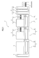
- Fig. 6 is a front view schematically showing the configuration of a part of the sample check unit 22.
- the horizontal rotation mechanism 223 has a contacting section 223d which is brought into contact with the upper end of the sample container 8 on the sample rack 9, and the contacting section 223d is configured to be horizontally rotated by a motor.
- the contacting section 223d is horizontally rotated while brought into contact with the cap section 8a of the sample container 8, the sample container 8 is horizontally rotated in the sample rack 9.
- the optical sensor 223a is disposed in front of the horizontal rotation mechanism 223.
- the optical sensor 223a is composed of a light-emitting element 223b and a light-receiving element 223c.
- the sample container 8 While the sample container 8 is horizontally rotated by the horizontal rotation mechanism 223, the sample container 8 is irradiated with light from the light-emitting element 223b and the light reflected is received by the light-receiving element 223c.
- a light-receiving level of the light-receiving element 223c exceeds a predetermined value, and when the bar-code label is not disposed on the face reflecting the light of the light-emitting element 223b, the light-receiving level is less than the predetermined value.
- the controller 226 checks the light-receiving level of the light-receiving element 223c of the optical sensor 223a while horizontally rotating the sample container 8, and stops the horizontal rotation operation of the horizontal rotation mechanism 223 at a position where the light-receiving level is equal to or less than the predetermined value. Accordingly, an angle of the sample container 8 is adjusted so that the face on which the bar-code label 8b is not disposed faces the front side.
- the bar-code reader 222b in the rear of the sample container 8 is opposed to the bar-code label 8b of the sample container 8.
- the bar-code reader 222b reads the specimen ID from the bar-code label 8b.
- the optical sensor 223a can be vertically moved by a vertical driving mechanism (not shown).
- the optical sensor 223a is disposed in front of the sample rack 9 when the sample rack 9 is on the transport path of the rack placing section 221.
- the optical sensor 223a is lifted by the vertical driving mechanism up to a position which does not interfere with the movement of the sample rack 9.
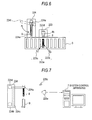
- Fig. 7 is a side view showing the schematic configuration of the sample container tilting mechanism 224.
- the sample container tilting mechanism 224 includes a grasping section 224a for grasping the vicinity of the top end of the sample container from both the right and left sides, a motor 224b, and a belt 224c for connecting a rotation shaft of the motor 224b with the grasping section 224a, and the grasping section 224a can be vertically moved by the rotation of the motor 224b. Furthermore, the grasping section 224a is connected to a rotation shaft of a motor 224d and the grasping section 224a can be rotated around a center axis extending in a front-back direction by the rotation of the motor 224d.
- the grasping section 224a of the sample container tilting mechanism 224 grasps the vicinity of the top end of the sample container 8 and is lifted in such a state, the sample container 8 is taken out from the sample rack 9.
- the lift operation of the grasping section 224a is stopped.
- the camera 225a is disposed in front of the sample container 8 positioned at the first imaging position 224e.
- a white LED 225c is disposed at a predetermined position with respect to the camera 225a and the sample container 8 is illuminated by the white LED 225c.
- Fig. 8 is a schematic diagram for illustrating a positional relationship among the camera 225a, the white LED 225c and the sample container 8, and a direction of the light emitted from the white LED.
- the white LED 225c is disposed, so that the light is emitted toward the sample container 8 positioned at the first imaging position 224e and the light reflected from the sample container 8 does not directly enter the camera 225a positioned in front of the sample container 8. Accordingly, the camera 225a is not directly exposed to the reflected light and so-called halation by overexposure can be prevented.
- the sample container 8 grasped at the first imaging position 224e by the grasping section 224a is imaged by the camera 225a while being in an erect state (vertical state), and the image data obtained in this manner is transmitted to the system control apparatus 7.
- the grasping section 224a is vertically rotated by the motor 224d to tilt the sample container 8.
- the grasping section 224a is turned by a predetermined angle so that a bottom portion of the sample container 8 reaches a second imaging position 224f positioned higher than the cap section 8a.
- the camera 225b (see Fig. 5 for reference) is disposed in front of the sample container 8 positioned at the second imaging position 224f.
- a white LED 225d (see Fig. 5 for reference) is disposed at a predetermined position with respect to the camera 225b and the sample container 8 is illuminated by the white LED 225d.
- a relative positional relationship between the white LED 225d and the camera 225b is the same as a relative positional relationship between the white LED 225c and the camera 225a. That is, the white LED 225d is disposed, so that the light is emitted toward the sample container 8 positioned at the second imaging position 224f, and the light reflected from the sample container 8 does not directly enter the camera 225b positioned in front of the sample container 8.
- the sample container 8 grasped at the second imaging position 224f by the grasping section 224a is imaged by the camera 225a while being tilted as described above, and the image data obtained in this manner is transmitted to the system control apparatus 7.
- the sample rack 9 in which all the sample containers 8 have been imaged is delivered from the rack delivery port 221b.
- the bar-code reader 222c is provided with a light-emitting section and a light-receiving section (line sensor) (not shown), and is connected to a main body of the sample check unit 22 by a flexible cable for transmitting an electric signal.
- the bar-code reader 222c is operated when the user manually re-reads a bar-code which cannot be read by the bar-code reader 222b.
- the blood sample analyzing system 1 is provided with the three sample transport apparatuses 3.
- the sample transport apparatuses 3 are disposed in front of the blood cell analyzing apparatuses 5 and the smear preparing apparatus 6, respectively.
- the neighboring sample transport apparatuses 3 are connected to each other and can deliver the sample rack 9.
- the rightmost sample transport apparatus 3 is connected to the above-described sample putting apparatus 2 to feed the sample rack 9 conveyed from the sample putting apparatus 2.
- the leftmost sample transport apparatus 3 is connected to the sample storing apparatus 4 to convey the sample rack 9 toward the sample storing apparatus 4.
- the respective sample transport apparatuses 3 are provided with a conveyor 31 and a rack slider 32.
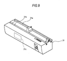
- Fig. 9 is a perspective view showing the configuration of the conveyor 31
- Fig. 10 is a perspective view showing the configuration of the rack slider 32.
- the conveyor 31 is provided with two rack transport paths 31a and 31b extending in a horizontal direction.
- the rack transport path 31a at the rear side is a measuring line for transporting the sample rack 9 containing a sample to be supplied to the blood cell analyzing apparatus 5 or the smear preparing apparatus 6.
- the rack transport path 31b at the front side is a skip line for transporting the sample rack 9 not containing a sample to be supplied to the blood cell analyzing apparatus 5 or the smear preparing apparatus 6.
- the conveyor 31 is provided with a controller 31c including a CPU and a memory and controlling the operating mechanism.
- the rack slider 32 is disposed on the right side of the conveyor 31 to sort and put the sample racks 9 into the measuring line 31a and the skip line 31b of the conveyor 31.
- the rack slider 32 is provided with one movable transport path 32a and the movable transport path 32a can be moved in a front-back direction by a motor (not shown).
- the above-described controller 31c controls the operation of the movable transport path 32a.
- the respective sample transport apparatuses 3 are provided with a rack bar-code reader (not shown) and the rack IDs read by the bar-code reader are provided to the controller 31c.
- the sample transport apparatus 3 is connected to the system control apparatus 7 to communicate therewith and is configured to receive a measuring order from the system control apparatus 7.
- the controller 31c determines whether a sample to be supplied to the blood cell analyzing apparatus 5 or the smear preparing apparatus 6 is contained in the sample rack 9 on the basis of the measuring order provided from the system control apparatus 7 and the rack ID read by the bar-code reader.
- the movable transport path 32a is moved to the back to deliver the sample rack 9 to the measuring line 31a.
- the movable transport path 32a is moved to the front to deliver the sample rack 9 to the skip line 31b. That is, the sample rack 9 containing only a sample which is not an analysis target of the blood cell analyzing apparatus 5 is transported to the skip line 31b in the sample transport apparatus 3 disposed in front of the blood cell analyzing apparatus 5.
- the sample rack 9 containing only a sample which is not a target for preparing a smear by the smear preparing apparatus 6 is transported to the skip line 31b in the sample transport apparatus 3 disposed in front of the smear preparing apparatus 6.
- the sample rack 9 contains a sample, which is an analysis target of the blood cell analyzing apparatus 5
- the sample rack 9 is transported to the measuring line 31a in the sample transport apparatus 3 disposed in front of the blood cell analyzing apparatus 5.
- the controller 31c repeats an operation of: moving the sample container which is a target of analysis (smear preparing process) to an aspiration position where the blood cell analyzing apparatus 5 (smear preparing apparatus 6) aspirates the sample; and moving the sample container which is the next analysis target (target for smear preparing process) to the aspiration position after the blood cell analyzing apparatus 5 (smear preparing apparatus 6) completes the aspiration of the sample.
- the sample storing apparatus 4 receives the sample rack 9, in which the analysis or smear preparing is completed, from the sample transport apparatus 3, and stores the sample rack. Since the configuration of the sample storing apparatus is the same as those of the sample delivery units 21a and 21b, a description thereof will be omitted.
- the blood cell analyzing apparatus 5 as an optical flow cytometry type multiple blood cell analyzing apparatus obtains the fluorescent intensity, the side-scattered light intensity and the like of blood cells included in a blood sample, classifies the blood cells included in the sample on the basis of the above intensities, and counts the number of blood cells for each type. Moreover, the blood cell analyzing apparatus 5 creates and displays a scattergram in which the classified blood cells are color-coded for each type.
- the blood cell analyzing apparatus 5 includes a measuring unit 51 for measuring a blood sample and an information processing unit 52 for processing measuring data output from the measuring unit 51 and displaying an analysis result of the blood sample.
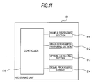
- Fig. 11 is a block diagram showing the schematic configuration of the measuring unit 51.
- the measuring unit 51 includes a sample dispensing section 511, a measuring sample preparing section 512, an optical detecting section 513, a signal processing circuit 514 and a controller 515.
- the sample dispensing section 511 is provided with an aspiration tube (not shown) and the aspiration tube is stuck into the cap section 8a of the sample container 8 in the sample rack 9 transported on the measuring line 31a of the sample transport apparatus 3 to aspirate a blood sample from the sample container 8.
- the measuring sample preparing section 512 is provided with a mixing container (not shown) to mix and stir the blood sample dispensed by the sample dispensing section 511 with a reagent and a diluent and prepare a measuring sample.
- the optical detecting section 513 is provided with a flow cell (not shown) to form a narrow flow of the measuring sample by supplying the measuring sample to the flow cell and exposing the measuring sample to light to obtain a side-scattered light signal, a forward-scattered light signal and a fluorescent signal by an optical sensor. These signals are output to the signal processing circuit 514.
- the signal processing circuit 514 processes an electric signal output from the optical detecting section 513.
- the signal processing circuit 514 obtains parameters such as peaks and pulse widths of the side-scattered light signal, the forward-scattered light signal and the fluorescent signal.
- the controller 515 is provided with a CPU and a memory, and is connected to the sample transport apparatus 3 to perform data communication therewith.
- the controller 515 controls the sample dispensing section 511, the measuring sample preparing section 512, the optical detecting section 513 and the signal processing circuit 514 in accordance with an analysis item provided from the sample transport apparatus 3, and performs a measuring operation corresponding to the analysis item.
- the controller is configured to transmit measuring data including the parameters obtained by the signal processing circuit 514 to the information processing unit 52.
- the measuring unit 51 can be operated in two operating modes which are a normal-measurement mode and a micro-measurement mode.
- a normal-measurement mode a smaller volume of a blood sample than in the normal-measurement mode is aspirated by the sample dispensing section 511, a measuring sample of a higher dilution ratio than in the normal-measurement mode is prepared by the measuring sample preparing section 512, and the measuring sample is optically measured by the optical detecting section 513.
- an analysis result obtained by the information processing unit 52 is corrected in accordance with the dilution ratio of the measuring sample. Accordingly, even when a slight volume of blood is measured, an analysis result can be obtained with excellent accuracy.
- the information processing unit 52 is composed of a computer.
- Fig. 12 is a block diagram showing the configuration of the information processing unit 52.
- the information processing unit 52 is realized by a computer 52a.
- the computer 52a includes a main body 521, an image display section 522 and an input section 523.
- the main body 521 includes a CPU 521a, a ROM 521b, a RAM 521c, a hard disk 521d, a reading device 521e, an I/O interface 521f, a communication interface 521g and an image output interface 521h.
- the CPU 521a, ROM 521b, RAM 521c, hard disk 521d, reading device 521e, I/O interface 521f, communication interface 521g and image output interface 521h are connected to each other by a bus 521j.
- the CPU 521a can execute a computer program loaded to the RAM 521c.
- the CPU 521a executes an analysis program 524a to be described later, so that the computer 52a functions as the information processing unit 52.
- the ROM 521b is composed of a mask ROM, a PROM, an EPROM an EEPROM or the like and the computer program executed by the CPU 521a and data used for the computer program are recorded in the ROM.
- the RAM 521c is composed of a SRAM, a DRAM or the like.
- the RAM 521c is used to read the analysis program 524a recorded in the hard disk 521d.
- the RAM is used as an operating area of the CPU 521a when the CPU 521a executes a computer program.
- various computer programs for execution by the CPU 521a such as an operating system and an application program, and data which are used to execute the computer programs are installed.
- the analysis program 524a to be described later is also installed in the hard disk 521d.
- the reading device 521e is composed of a flexible disk drive, a CD-ROM drive, a DVD-ROM drive or the like and can read the computer program or data recorded in a portable recording medium 524.
- the analysis program 524a for prompting the computer to function as the information processing unit 52 is stored.
- the computer 52a can read the analysis program 524a from the portable recording medium 524 and install the analysis program 524a in the hard disk 521d.
- the analysis program 524a is provided by the portable recording medium 524 and can be also provided from an external device, which is connected to the computer 52a by an electric communication line (which may be wired or wireless) to communicate therewith, through the electric communication line.
- the analysis program 524a is stored in a hard disk of a server computer on the internet and the computer 52a accesses the server computer to download the computer program and install the computer program in the hard disk 521d.
- the analysis program 524a operates on the above operating system.
- the I/O interface 521f is composed of, for example, a serial interface such as USB, IEEE1394 or RS-232C, a parallel interface such as SCSI, IDE or IEEE1284, and an analog interface including a D/A converter and an A/D converter.
- the input section 523 composed of a keyboard and a mouse is connected to the I/O interface 521f and the user uses the input section 523 to input data to the computer 52a.
- the communication interface 521g is an Ethernet (registered trade name) interface.
- the communication interface 521g is connected to the measuring unit 51 via a LAN. Thanks to the communication interface 521g, the computer 52a sends and receives data to and from the measuring unit 51 connected to the LAN by using a predetermined communication protocol.
- the image output interface 521h is connected to the image display section 522 composed of a LCD or a CRT to output a picture signal corresponding to the image data provided from the CPU 521a to the image display section 522.
- the image display section 522 displays an image (screen) in accordance with an input picture signal.
- the smear preparing apparatus 6 aspirates a blood sample so as to deliver drops of it onto a slide glass, spreads and dries the blood sample on the slide glass, and supplies a stain solution to the slide glass to stain the blood on the slide glass. In this manner, the smear preparing apparatus prepares a smear.
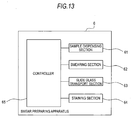
- Fig. 13 is a block diagram showing the schematic configuration of the smear preparing apparatus 6.
- the smear preparing apparatus 6 includes a sample dispensing section 61, a smearing section 62, a slide glass transport section 63, a staining section 64 and a controller 65.
- the sample dispensing section 61 is provided with an aspiration tube (not shown) and the aspiration tube is stuck into the cap section 8a of the sample container 8 in the sample rack 9 transported on the measuring line 31a of the sample transport apparatus 3 to aspirate a blood sample from the sample container 8.
- the sample dispensing section 61 is configured to drip the aspirated blood sample onto a slide glass.
- the smearing section 62 is configured to smear and dry the blood sample dripped onto the slide glass and perform printing on the slide glass.
- the slide glass transport section 63 is provided to receive the slide glass on which the blood sample is smeared by the smearing section 62 in a cassette (not shown) and to transport the cassette.
- the staining section 64 supplies a stain solution to the slide glass in the cassette transported to a staining position by the slide glass transport section 63.
- the controller 65 controls the sample dispensing section 61, the smearing section 62, the slide glass transport section 63 and the staining section 64 in accordance with a smear preparing instruction issued from the sample transport apparatus 3 so as to perform the above smear preparing operation. When the smear preparation is completed, the controller 65 transmits a notification of the completion of the preparation of the smear to the sample transport apparatus 3.
- the system control apparatus 7 is composed of a computer and controls the entire blood sample analyzing system 1.
- the system control apparatus 7 receives a specimen ID and a rack ID from the sample putting apparatus 2 so as to obtain a measuring order from a host computer (not shown) by the specimen ID as a key. Furthermore, the system control apparatus 7 performs image processing of the images captured by and output from the cameras 225a and 225b to determine whether a blood sample in a storing container is coagulated and to detect the volume of the blood sample in the sample container. Moreover, the system control apparatus 7 transmits the measuring order to the sample transport apparatus 3.
- the system control apparatus 7 is realized by a computer 7a.
- the computer 7a includes a main body 71, an image display section 72 and an input section 73.
- the main body 71 includes a CPU 71a, a ROM 71b, a RAM 71c, a hard disk 71d, a reading device 71e, an I/O interface 71f, a communication interface 71g and an image output interface 71h.
- the CPU 71a, ROM 71b, RAM 71c, hard disk 71d, reading device 71e, I/O interface 71f, communication interface 71g and image output interface 71h are connected to each other by a bus 71j .
- various computer programs for execution by the CPU 71a such as an operating system and an application program, and data which are used to execute the computer programs are installed.
- a system control program 74a to be described later is also installed in the hard disk 71d.
- the reading device 71e is composed of a flexible disk drive, a CD-ROM drive, a DVD-ROM drive or the like and can read the computer program or data recorded in a portable recording medium 74.
- the system control program 74a for prompting the computer to function as the system control apparatus 7 is stored.
- the computer 7a can read the system control program 74a from the portable recording medium 74 to install the system control program 74a in the hard disk 71d.
- the I/O interface 71f is composed of, for example, a serial interface such as USB, IEEE1394 or RS-232C, a parallel interface such as SCSI, IDE or IEEE1284, and an analog interface including a D/A converter and an A/D converter.
- the input section 73 composed of a keyboard and a mouse is connected to the I/O interface 71f and the user uses the input section 73 to input data to the computer 52a.
- the cameras 225a and 225b provided in the above-described sample check unit 22 are connected to the I/O interface 71f to take the images captured by the cameras 225a and 225b.
- the communication interface 71g is an Ethernet (registered trade name) interface.
- the communication interface 71g is connected to the sample putting apparatus 2, the sample transport apparatus 3, the sample storing apparatus 4 and the host computer (not shown) via a LAN.
- the computer 7a sends and receives data to and from the above respective apparatuses connected to the LAN by using a predetermined communication protocol.
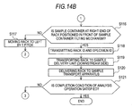
- Figs. 14A and 14B are flowcharts showing the flow of an operation of the sample putting apparatus 2.
- the user places the sample rack 9 storing the sample container 8 in the rack placing section 211 of the sample delivery unit 21a and operates the operating panel 214 of the sample delivery unit 21a to issue an instruction to start analysis to the blood sample analyzing system 1.
- the controller 213 of the sample delivery unit 21a receives the instruction to start analysis (Step S101) and starts movement of the sample rack 9 in accordance with the instruction (Step S102).
- the sample rack 9 placed in the rack placing section 211 of the sample delivery unit 21a is moved to the back on the rack placing section 211. Then, the sample rack 9 is moved to the left to be transferred to the sample check unit 22.
- Step S103 the sample rack 9 fed to the sample check unit 22 is moved for every pitch to the left on the transport path of the rack placing section 221 (Step S103).
- a rack bar-code of the sample rack 9 is read by the bar-code reader 222a and provided to the controller 226 (Step S104).
- the controller 226 determines whether the sample container 8 is positioned in front of the horizontal rotation mechanism 223 (Step S105). This process is performed, by referring to, for example, a light-receiving level of the light-receiving element 223c of the optical sensor 223a.
- Step S105 the controller 226 returns the process to Step S110.
- Step S105 when the sample container 8 is positioned in front of the horizontal rotation mechanism 223 (Yes in Step S105), the controller 226 compares the light-receiving level of the light-receiving element 223c of the optical sensor 223a with a predetermined value (Step S107), while bringing the contacting section 223d into contact with the cap section 8a of the sample container 8 and rotating the contacting section (Step S106). When the light-receiving level is equal to or less than the predetermined value (No in Step S107), the controller returns the process to Step S106 and thus the horizontal rotation of the sample container 8 is continued.
- Step S107 when the light-receiving level exceeds the predetermined value (Yes in Step S107), the controller 226 stops the horizontal rotation of the contacting section 223d (Step S108) and causes the bar-code reader 222b to read the specimen bar-code (Step S109).
- Step S110 determines whether the sample container 8 is disposed in front of the sample container tilting mechanism 224 (Step S110). This process is performed by, for example, determining how many times the sample container 8 disposed in front of the horizontal rotation mechanism 223 has been subjected to pitch feeding.
- Step S110 the controller 226 performs a process of Step S116.
- Step S110 When the sample container 8 is disposed in front of the sample container tilting mechanism 224 (Yes in Step S110), the controller 226 grasps the sample container 8 by the grasping section 224a to lift the sample container to the first imaging position on the upper side (Step S111), and transmits a first image taking instruction signal to the system control apparatus 7 (Step S112). As described later, the system control apparatus 7 takes an image captured by the camera 225a when receiving the first image taking instruction signal, and then performs image processing on the image and detects the blood volume in the sample container 8.
- the controller 226 vertically turns the grasping section 224a by a predetermined angle to tilt the sample container 8 to the second imaging position (Step S113) and transmits a second image taking instruction signal to the system control apparatus 7 (Step S114).
- the system control apparatus 7 takes an image captured by the camera 225b when receiving the second image taking instruction signal, and then performs image processing on the image and determines the presence or absence of blood coagulation in the sample container 8.
- the controller 226 turns the grasping section 224a in the counter direction to return the sample container 8 to the vertical state again, and moves the grasping section 224a downward to store the sample container 8 in the sample rack 9 (Step S115).
- Steps S105 to S109 and the processes of Steps S110 to S115 have been described so as to be sequentially performed. However, actually, the processes are performed in parallel. That is, for example, while one sample container 8 stored in the sample rack 9 is horizontally rotated, a different sample container 8 is pulled from the sample rack 9 of the sample containers 8.
- the controller 226 determines whether all the sample containers 8 stored in the sample rack 9 have been subjected to the above processes, or more precisely, whether a sample container storing section at the right end of the sample rack 9 is positioned in front of the sample container tilting mechanism 224 (Step S116). When the right end of the sample rack 9 is not yet positioned in front of the sample container tilting mechanism 224 (No in Step S116), the controller moves the sample rack 9 to the left by one pitch (Step S117) and returns the process to Step S105.
- Step S118 When the right end of the sample rack 9 is positioned in front of the sample container tilting mechanism 224 (Yes in Step S116), the controller 226 transmits the rack ID of the sample rack 9 and specimen IDs of all the sample containers 8 stored in the sample rack 9 to the system control apparatus 7 (Step S118).
- holding positions (1 to 10) of the sample containers 8 in the sample rack 9 correspond to the specimen IDs of the held sample containers.
- the controller 226 further moves the sample rack 9 to the left to deliver the sample rack 9 to the sample delivery unit 21b (Step S119).
- the controller 213 of the sample delivery unit 21b moves the received sample rack 9 (Step S120).
- the sample rack 9 is moved on the rack placing section 211 of the sample delivery unit 21b and then moved to the left to be transferred to the sample transport apparatus 3.
- the controller 213 of the sample delivery unit 21a determines whether the conditions for completion of the analysis operation (an analysis completion instruction is issued from the user, or the sample rack 9 is not on the rack placing section 211 of the sample delivery unit 21a) are satisfied (Step S121). When the conditions are not satisfied (No in Step S121), the controller returns the process to Step S102, and when the conditions are satisfied (Yes in Step S121), the controller completes the process.
- the system control apparatus 7 obtains a measuring order of a specimen (blood sample) from the specimen ID received from the sample putting apparatus 2.
- the measuring order is data indicating the instruction of the analysis item for blood sample analysis, and includes attribute information of the specimen, such as the specimen ID, patient ID and name of the patient, and information of the analysis item.
- Fig. 15 is a flowchart showing the procedure of a process of obtaining a measuring order. As shown in Fig. 15 , when the system control apparatus 7 receives the rack ID and specimen IDs transmitted from the sample putting apparatus 2 (Step S131), an interrupt request is generated for the CPU 71a of the system control apparatus 7 and a process of Step S132 is invoked.
- Step S132 the CPU 71a transmits one of the received specimen IDs and requests a measuring order corresponding to the specimen ID from a host computer (not shown) (Step S132).
- the CPU 71a stands by to receive the measuring order (No in Step S133), and when the system control apparatus 7 receives the measuring order transmitted from the host computer (Yes in Step S133), the CPU associates the received measuring order with the rack ID and stores the measuring order in the hard disk 71d (Step S134).
- the CPU 71a determines whether the specimen IDs corresponding to the rack ID, that is, all the specimen IDs of all the sample containers 8 stored in the sample rack 9 having the rack ID have been subjected to a measuring order inquiry (Step S135).
- Step S135 When there is a specimen ID yet to be subjected to a measuring order inquiry (No in Step S135), the CPU 71a returns the process to Step S132 and requests a measuring order corresponding to the specimen ID not yet subjected to the measuring order inquiry from the host computer.
- Step S1305 when all the specimen IDs have been subjected to the measuring order inquiry (Yes in Step S135), the CPU 71a completes the process.
- system control apparatus 7 takes an image captured by the camera 225a and performs image processing of the image to detect a blood volume in the sample container 8.
- Fig. 16 is a flowchart showing the procedure of a blood volume detecting process. As shown in Fig. 16 , when the system control apparatus 7 receives the first image taking instruction signal transmitted from the sample putting apparatus 2 (Step S141), an interrupt request is generated for the CPU 71a of the system control apparatus 7 and a process of Step S142 is invoked.
- Step S142 the CPU 71a takes the image captured by the camera 225a at that time (Step S142).
- the CPU 71a detects the width of an image of the sample container 8 in the taken image (Step S143).
- Fig. 17 is a schematic diagram for illustrating a process of detecting the width of the image of the sample container 8.
- An image 100 is a color image and has luminance information of RGB of respective pixels.
- a processing area 101 for obtaining the width of the sample container 8 in the image 100 is subjected to the following process by the CPU 71a.
- the processing area 101 is a predetermined area, which includes an image of the vicinity of the bottom portion of the sample container 8 and does not include an image of the bar-code label.
- the CPU 71a For each X coordinate in the processing area 101, the CPU 71a accumulates B (blue) luminance values (hereinafter, referred to as "B value”) of the pixels in a Y direction in the processing area 101. That is, an accumulation value (hereinafter, referred to as "B luminance accumulation value”) of the B values of the pixels in a column of pixel groups at the left end included in the processing area 101 is calculated, and the B luminance accumulation value of a column of pixel groups on the right side thereof is calculated. This operation is repeated while incrementing an X coordinate value until the right end of the processing area 101 is reached.
- B value blue luminance values
- a graph of the B luminance accumulation value obtained as described above in the processing area 101 is denoted by reference numeral 101a.
- the B luminance accumulation value related to the processing area 101 is high in a background image and is low in the image of the sample container 8. Accordingly, the CPU 71a differentiates the B luminance accumulation value in an X direction and detects a portion in which the B luminance accumulation value is sharply lowered and a portion in which the B luminance accumulation value sharply increases. In this manner, the width of the sample container 8 is detected.
- Fig. 18 is a schematic diagram for illustrating a process of detecting the positions of the right and left ends of an image of the bar-code label 8b.
- a processing area 102 for detecting the positions of the right and left ends of the image of the bar-code label 8b in the image 100 is subjected to the following process by the CPU 71a.
- the processing area 102 is a predetermined area, which is an upper portion in the image and includes the image of the bar-code label. For each X coordinate value in the processing area 102, the CPU 71a calculates a B luminance accumulation value.
- a graph of the B luminance accumulation value in the processing area 102 is denoted by reference numeral 102a.
- the B luminance accumulation value related to the image of the bar-code label is higher than the B luminance accumulation value related to the background image and the image of the sample container.
- the CPU 71a scans the B luminance accumulation value from left to right and detects as the position of the image of the left end of the bar-code label a position where the B luminance accumulation value becomes high and is then sharply lowered.
- the CPU scans the B luminance accumulation value from the right to the left and detects as the position of the image of the right end of the bar-code label a position where the B luminance accumulation value becomes high and is then sharply lowered.
- Fig. 19 is a schematic diagram for illustrating a process of detecting the position of the lower end of the image of the sample container.
- the CPU 71a determines a processing area 103 for detecting the position of the lower end of the image of the sample container and the position of an image of a liquid surface of the blood sample in the image 100.
- the processing area 103 is an area at the slightly inner side of an area surrounded by the positions of the images of the right and left ends of the bar-code label detected in Step S144. This is because the image of the bar-code label does not exist in the area between the image of the left end and the image of the right end of the bar-code label.
- the CPU 71a calculates a B luminance accumulation value by accumulating B values in an X direction, and calculates an R luminance accumulation value by accumulating R values. In addition, for each Y coordinate, the CPU 71a calculates a value (hereinafter, referred to as "R/B accumulation luminance ratio") which is obtained by dividing the R luminance accumulation value by the B luminance accumulation value.
- R/B accumulation luminance ratio a value which is obtained by dividing the R luminance accumulation value by the B luminance accumulation value.
- the B luminance accumulation value of the image of the blood sample in the sample container is lower than the B luminance accumulation values of the background image and an image of a portion in which the blood sample in the sample container does not exist.
- the R/B accumulation luminance ratio is higher than in the other portion. Accordingly, the CPU 71a differentiates the B luminance accumulation value in a Y direction, and detects as the position of the lower end of the image of the sample container a position where the B luminance accumulation value is sharply lowered in a direction toward the upper side from the lower end of the processing area 103.
- the CPU 71a determines whether a blood plasma portion and a blood cell portion are separated in the blood sample (Step S146). In this process, it is determined that the blood plasma portion and the blood cell portion are separated, when the B luminance accumulation value and the R luminance accumulation value of the processing area 103 are scanned from the position of the lower end of the image of the sample container to the upper side and only the R luminance accumulation value is large.
- Step S146 the CPU 71a performs a first liquid surface image position detecting process of detecting the position of the image of the liquid surface of the blood sample (Step S147).
- Step S148 the CPU performs a second liquid surface image position detecting process of detecting the position of the image of the liquid surface of the blood sample (Step S48).
- a position, where the B luminance accumulation value becomes large sharply in a direction toward the upper side from the lower end of the image of the sample container is detected as the position of the image of the liquid surface.
- the CPU 71a calculates the blood volume in the sample container 8 (Step S149). In this process, the CPU 71a calculates a blood volume BV by the following expressions (1) and (2).
- R denotes a radius of an inner face of a sample container
- k denotes a coefficient determined by scale of a captured image
- W denotes a width of an image of a sample container
- T denotes a thickness of a sample container
- H denotes a height (the difference between a position of an image of a liquid surface and a position of an image of the lower end of a sample container) of an image of a blood sample.
- the CPU 71a When calculating the blood volume BV, the CPU 71a associates the blood volume with the measuring order having the specimen ID of the blood sample as a target of imaging process, stores the blood volume in the hard disk 71d (Step S1410), and then completes the process.
- the system control apparatus 7 takes an image captured by the camera 225b and performs image processing of the image to determine whether the blood sample in the sample container 8 is coagulated.
- Fig. 20 is a flowchart showing the procedure of a blood coagulation determining process. As shown in Fig. 20 , when the system control apparatus 7 receives the second image taking instruction signal transmitted from the sample putting apparatus 2 (Step S151), an interrupt request is generated for the CPU 71a of the system control apparatus 7 and a process of Step S152 is invoked.
- Step S152 the CPU 71a takes the image captured by the camera 225b at that time (Step S152).
- the CPU 71a detects the position of the left end of an image of the sample container 8 in the taken image (Step S153).
- Fig. 21 is a schematic diagram for illustrating a process of detecting the position of the left end of the image of the sample container 8.
- An image 110 is a color image and has luminance information of RGB of respective pixels.
- a processing area 111 for obtaining the position of the left end of the image of the sample container 8 in the image 110 is subjected to the following process by the CPU 71a.
- the processing area 111 is a predetermined area, which includes an image of the vicinity of the bottom portion of the sample container 8.
- the CPU 71a calculates a B luminance accumulation value in a Y direction in the processing area 111.
- a graph of the B luminance accumulation value in the processing area 111 is denoted by reference numeral 111a.
- the B luminance accumulation value related to the image of the sample container is lower than the B luminance accumulation value related to a background image. Accordingly, the CPU 71a differentiates the B luminance accumulation value in an X direction and detects as the position of the left end of the image of the sample container a position where the B luminance accumulation value scanned from left to right is lowered.
- Fig. 22 is a schematic diagram for illustrating a process of detecting the position of the upper end of the image of the bottom portion of the sample container.
- the CPU 71a determines a processing area 112 for detecting the position of the upper end of the image of the bottom portion of the sample container in the image 110.
- the processing area 112 is an area from the position of the left end of the image of the sample container detected in Step S153 to a position positioned on the right side thereof by a predetermined number of pixels.
- the sample container 8 is imaged in a state in which the bottom portion of the sample container 8 is positioned higher than the cap section 8a in the image, and it is required that the image of the bottom portion of the sample container is included in the processing area so that the bottom portion of the sample container 8 becomes the upper end of the sample container, the image of the bottom portion of the sample container 8 exists in an area on the right side of the position of the left end.
- the CPU 71a calculates a B luminance accumulation value in the X direction in the processing area 112.
- a graph of the B luminance accumulation value in the processing area 112 is denoted by reference numeral 112a.
- the B luminance accumulation value related to the image of the sample container is lower than the B luminance accumulation value related to the background image. Accordingly, the CPU 71a differentiates the B luminance accumulation value in the Y direction, and detects as the position of the upper end of the image of the bottom portion of the sample container a position where the B luminance accumulation value is lowered when the B luminance accumulation value is scanned from the upper side to the lower side.
- the CPU 71a detects the position of the image of the liquid surface of the blood sample (Step S155). This process will be described in detail.
- the CPU 71a subjects a processing area 113 (see Fig. 22 for reference) for detecting the position of the image of the liquid surface of the blood sample in the image 110 to the following process.
- the processing area 113 is a predetermined area, which is positioned on the right side in the image 110.
- the processing area 113 is provided in this portion and thus the processing area 113 includes an image of the liquid blood without an image of the clot.
- the processing area 113 is suitable for detection of the liquid surface image, which is an image of a surface of liquid.
- the CPU 71a calculates a B luminance accumulation value and an R luminance accumulation value.
- a graph of the B luminance accumulation value in the processing area 113 is denoted by reference numeral 113a.
- the CPU 71a sequentially checks an R/B accumulation luminance ratio toward the upper side from the lower end of the processing area 113 and determines whether the R/B accumulation luminance ratio is equal to or greater than a predetermined value.
- the R/B accumulation luminance ratio is large in the blood image.
- the R/B accumulation luminance ratio is equal to or greater than the predetermined value, it can be determined that the blood is in the sample container.
- the R/B accumulation luminance ratio does not exceed the predetermined value in a direction of a Y axis of the entire processing area 113, it is regarded that detection of the position of the image of the liquid surface of the blood sample failed.
- the CPU 71a checks the B luminance accumulation value toward the upper side from a position (the R/B accumulation luminance ratio is equal to or greater than the predetermined value) where it is considered that the blood exists to detect a position, where a differential value of the B luminance accumulation value is equal to or greater than a predetermined value and the R/B accumulation luminance ratio is equal to or less than a predetermined value, as the position of the image of the blood surface.
- a position where a differential value of the B luminance accumulation value is equal to or greater than a predetermined value and the R/B accumulation luminance ratio is equal to or less than a predetermined value
- Step S156 determines whether the detection of the position of the image of the blood surface in Step S155 succeeded.
- Step S157 a processing area for determining the presence or absence of blood coagulation is set based on the positions of the left and upper ends of the image of the bottom portion of the sample container and the position of the image of the blood surface. This processing area will be described with reference to Fig. 22 .
- a processing area 114 which is positioned on the right side of the left end of the image of the bottom portion of the sample container, on the lower side of the upper end of the image of the bottom portion of the sample container, and on the upper side of the image of the blood surface, is set.
- the clot protrudes upward from the liquid surface in some cases.
- the image of the clot is in the processing area 114 positioned on the upper side of the image of the liquid surface.
- the processing area 114 is subjected to image processing and thus the coagulation of the blood can be detected.
- a processing area for determining the presence or absence of blood coagulation is set based on the positions of the left and upper ends of the image of the bottom portion of the sample container (Step S158).
- Fig. 23 is a schematic diagram for illustrating a processing area for determining blood coagulation when the detection of the position of the image of the blood surface fails. As shown in Fig. 23 , a processing area 115 having a predetermined size is positioned on the right side of the left end of the image of the bottom portion of the sample container and on the lower side of the upper end of the image of the bottom portion of the sample container in this case.
- the blood has viscosity due to coagulation and adheres to the inner face of the sample container in some cases.
- the liquid surface cannot be confirmed even if the sample container 8 is tilted, and the blood image occupies a large portion of the processing area 115.
- the processing area 115 is subjected to image processing and thus the coagulation of the blood can be detected.
- the CPU 71a determines the presence or absence of blood coagulation (Steps S159). This process will be described as follows. For each pixel included in the processing area 114 and the processing area 115, the CPU 71a calculates an R/B luminance ratio which is a ratio of an R value to a B value of a single pixel. In addition, the CPU 71a counts the number of pixels, each of which has the B value equal to or less than a predetermined value and the R/B luminance ratio equal to or less than a predetermined value, among all the pixels included in the processing area 114 or 115. When the number of pixels is equal to or greater than a predetermined value, it is determined that the blood is coagulated. When the number of pixels is less than the predetermined value, it is determined that the blood is not coagulated.
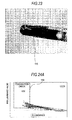
- Fig. 24A is a scattergram showing a distribution state related to the B values and the R/B luminance ratios of the pixels in the processing area 114 in the image shown in Fig. 22
- Fig. 24B is a scattergram showing a distribution state related to the B values and the R/B luminance ratios of the pixels in the processing area 115 in the image shown in Fig. 23
- Fig. 24C is a scattergram showing a distribution state related to the B values and the R/B luminance ratios of the pixels in the processing area 114 for the blood which is not coagulated.
- a range satisfying the condition that the B value is equal to or less than a predetermined value and the R/B luminance ratio is equal to or less than a predetermined value is represented by a rectangular frame 150.
- a large number of pixels severe hundred pixels or more when the image 100 has a size of 640 x 480 dots
- a large number of pixels in all the pixels included in the processing area 114 satisfy the above condition.
- Fig. 24A when a clot protrudes on a blood surface, a large number of pixels (several hundred pixels or more when the image 100 has a size of 640 x 480 dots) in all the pixels included in the processing area 114 satisfy the above condition.
- the CPU 71a When determining the presence or absence of blood coagulation, the CPU 71a associates a determination result with the measuring order having the specimen ID of the blood sample as a target of image processing and stores the result in the hard disk 71d (Step S1510), and then completes the process.
- the sample transport apparatus 3 transmits a rack ID to the system control apparatus 7 to request a measuring order corresponding to the rack ID.
- the system control apparatus 7 transmits the measuring order to the sample transport apparatus 3 in accordance with the request.
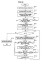
- Fig. 25 is a flowchart showing the procedure of a measuring order transmitting process. As shown in Fig. 25 , when the request data of the measuring order including the rack ID transmitted from the sample transport apparatus 3 is received by the system control apparatus 7 (Step S161), an interrupt request is generated for the CPU 71a of the system control apparatus 7 and a process of Step S162 is invoked.
- Step S162 the CPU 71a searches the measuring order corresponding to the received rack ID from the hard disk 71d.
- the CPU 71a sets a variable i indicating a holding position of the sample rack to 1 (Step S163) and determines whether i is equal to or less than 10 (Step S164).
- Step S164 the CPU 71a determines whether the sample container is held at a holding position i (whether there is the measuring order corresponding to the holding position i) (Step S165).
- the CPU 71a performs a process of Step S1612.
- Step S165 it is determined whether blood coagulation is detected in the sample at the holding position i (Step S166) .
- Step S166 the CPU 71a performs a process of Step S1612.
- Step S166 when the blood coagulation is not detected in the sample at the holding position i (No in Step S166), the CPU 71a reads the measuring order of the blood sample at the holding position i from the hard disk 71d (Step S167) .
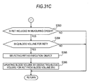
- the CPU 71a determines a blood volume K necessary for analysis from an analysis item included in the measuring order (Step S168) and compares a blood volume BV detected in the blood sample at the holding position i with the necessary blood volume K to determine whether the expression BV ⁇ K is satisfied (Step S169).
- the CPU 71a stores measuring order information in which the holding position i is associated with the measuring order in the RAM 71c (Step S1610) and performs a process of Step S1612.
- Step S169 when BV is less than K (No in Step S169), the CPU 71a stores measuring order information in which the holding position i, the measuring order and information instructing the micro-measurement mode are associated with each other in the RAM 71c (Step S1611) and performs a process of Step S1612. In Step S1612, the CPU 71a increments i by 1 and returns the process to Step S164. In Step S164, when i is not equal to or less than 10 (No in Step S164), the CPU 71a transmits the measuring order information stored in the RAM 71c to the sample transport apparatus 3 of a measuring order request source (Step S1613) and completes the process.
- Fig. 26 is a flowchart showing the flow of the operation of the sample transport apparatus 3.
- a sensor (not shown) detects the arrival of the sample rack 9.
- Step S171 a detection signal of the sample rack 9 is provided to the controller 31c from the sensor (Step S171), an interrupt request is generated for the CPU of the controller 31c and a process of Step S172 is invoked.
- Step S172 the controller 31c reads the rack bar-code of the sample rack 9 by a bar-code reader (not shown) to obtain a rack ID.
- the controller 31c. transmits measuring order request data including the rack ID to the system control apparatus 7 (Step S173).
- the controller 31c stands by to receive the measuring order information from the system control apparatus 7 (No in Step S174).
- Fig. 27 is a schematic diagram showing the data structure of the measuring order information.
- the data stored in the memory of the sample transport apparatus 3 by the process of Step S175 is configured by a rack ID 160 and measuring order information 161a to 161j about the blood samples held in the sample rack 9.
- the measuring order information 161a to 161j includes holding position information, a measuring order and micro-measurement mode instruction data.
- the measuring order includes a specimen ID and analysis item data.
- Step S176 After storing the measuring order information in the memory, the controller 31c sets a variable i indicating the holding position of the sample rack to 1. (Step S176) and determines whether i is equal to or less than 10 (Step S177). When i is equal to or less than 10 (Yes in Step S177), the controller 31c moves the sample container 8 at the holding position i to an aspiration position, where the blood cell analyzing apparatus 5 aspirates the sample, by the measuring line 31a (Step S178) and determines whether there is measuring order information about the sample at the holding position i in the measuring order information in the memory (Step S179). When there is no measuring order information (No in Step S179), the controller 31c performs a process of Step S1712.
- Step S179 when there is measuring order information about the sample at the holding position i (Yes in Step S179), the controller 31c transmits aspiration instruction data including the analysis item data and the specimen ID included in the measuring order information to the blood cell analyzing apparatus 5 (Step S1710).
- the micro-measurement mode instruction data is included in the aspiration instruction data.
- the controller 31c stands by to receive an aspiration completion notification signal from the blood cell analyzing apparatus 5 (No in Step S1711).
- the controller 31c performs a process of Step S1712.
- Step S1712 the controller 31c increments i by 1 and returns the process to Step S177.
- Step S177 when i is not equal to or less than 10 (No in Step S177), the controller 31c conveys the sample rack 9 to the apparatus on the downstream side of transport (Step S1713) and completes the process.
- the sample container 8 containing the blood sample is stopped at an aspiration position, and is then transported from the aspiration position without issuing aspiration instruction data.
- the sample container 8 is stopped at the aspiration position, and then aspiration instruction data is issued. This blood sample is aspirated by the measuring unit 51 as described later, and an aspiration completion notification signal is then issued and the blood sample is transported from the aspiration position.
- Aspiration of the blood sample requires a predetermined time (for example, two seconds) and the predetermined time is longer than the time (for example, one second) when the sample container of the blood sample which is determined to have coagulated is stopped at the aspiration position. In this manner, by moving the blood sample, which does not require aspiration, from the aspiration position in a short time, a large number of blood samples cam be efficiently analyzed.
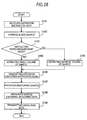
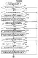
- Fig. 28 is a flowchart showing the flow of an operation of the measuring unit 51 of the blood cell analyzing apparatus 5.
- Step S182 the controller 515 stirs a blood sample in the sample container. Then, the controller 515 determines whether the aspiration instruction data includes micro-measurement mode instruction data (Step S183). When the micro-measurement mode instruction data is included (Yes in Step S183), the sample dispensing section 511 aspirates a smaller volume of the blood sample than in the normal-measurement mode (Step S184). When the micro-measurement mode instruction data is not included (No in Step S183), the controller 515 causes the sample dispensing section 511 to aspirate a general volume of the blood sample (Step S185). Next, the controller 515 transmits an aspiration completion notification signal to the sample transport apparatus 3 (Step S186).
- the controller 515 causes the measuring sample preparing section 512 to mix the aspirated blood sample with a reagent and a diluent and prepare a measuring sample (Step S187) and then supplies the prepared measuring sample to the optical detecting section 513 to obtain measuring data including parameters such as peaks and pulse widths of a side-scattered light signal, a forward-scattered light signal and a fluorescent signal (Step S188).
- the controller 515 transmits the measuring data to the information processing unit 52 (Step S189) and completes the process.
- the information processing unit 52 analyzes the received measuring data to classify blood cells included in the blood sample and count the number of blood cells for every type of blood cell. Furthermore, the information processing unit 52 creates a scattergram or a histogram and stores the analysis result data including the specimen ID and these analysis results in the hard disk 521d. The image display section 522 displays an analysis result screen showing the analysis results. The analysis result data is transmitted from the information processing unit 52 to the host computer and stored by the host computer.
- the sample rack 9 delivered from the sample transport apparatus 3 on the downmost-stream side of transport is fed to the sample storing apparatus 4.
- the sample storing apparatus 4 transports the sample rack on the rack placing section and stores the sample rack.
- Fig. 29 is a block diagram showing the configuration of a blood sample analyzing apparatus 200 according to this embodiment.
- the blood sample analyzing apparatus 200 as an optical flow cytometry type multiple blood cell analyzing apparatus obtains fluorescent intensity, side-scattered light intensity and the like of blood cells included in a blood sample, classifies the blood cells included in the sample on the basis of the above fluorescent intensity, side-scattered light intensity and the like, and counts the number of blood cells for every type. Moreover, the blood sample analyzing apparatus 200 creates and displays a scattergram in which the classified blood cells are color-coded for every type.
- the blood sample analyzing apparatus 200 includes a measuring unit 250 for measuring a blood sample and an information processing unit 270 for processing measuring data output from the measuring unit 250 and displaying an analysis result of the blood sample.
- the measuring unit 250 includes a sample dispensing section 251, a measuring sample preparing section 252, an optical detecting section 253, a signal processing circuit 254, a rack transport section 255, bar-code readers 256 and 257, a horizontal rotation mechanism 258, a sample container tilting mechanism 259 and a controller 260.
- the rack transport section 255 can transport the sample rack 9 and is configured to transport the sample container 8 held in the sample rack 9 to an aspiration position for aspirating the sample in the sample container 8 by the sample dispensing section 251 and to move the sample container 8 in which aspiration is completed from the aspiration position.
- the rack transport section 255 is provided with a before-analysis placing table for placing the sample rack 9 storing the sample container 8 before analysis, an after-analysis placing table for storing the sample rack 9 storing the sample container 8 after analysis, and a transport path for the sample rack 9 from the before-analysis placing table to the after-analysis placing table through the aspiration position (not shown).
- the horizontal rotation mechanism 258 and the sample container tilting mechanism 259 are provided and the bar-code reader 256 for reading a rack bar-code of the sample rack 9 on the transport path and the bar-code reader 257 for reading the specimen bar-code of the sample container 8 are provided.
- Two cameras and two white LEDs are disposed in front of the sample container tilting mechanism 259.
- One of the cameras images the sample container 8 which is taken out from the sample rack 9 and held in a vertical state by the sample container tilting mechanism 259, and the other camera images the sample container 8 which is vertically rotated and held in a state in which a bottom portion of the sample container 8 is positioned higher than a cap section 8a by the sample container tilting mechanism 259.
- These cameras are connected to the information processing unit 270 by a cable for transmitting the electric signals of captured images. Since the configurations and arrangement of the horizontal rotation mechanism 258, the sample container tilting mechanism 259, the cameras and the white LEDs are the same as in the first embodiment, a description thereof will be omitted.
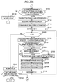
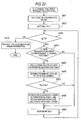
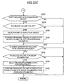
- FIGs. 30A to 30C are flowcharts showing the flow of an operation of the blood sample analyzing apparatus 200 according to this embodiment.
- Fig. 30A is a flowchart showing the flow of a measurement start instruction operation of the information processing unit 270
- Figs. 30B and 30C are flowcharts showing the flow of a sample measuring operation of the measuring unit 250 in the sample analysis operation of the blood sample analyzing apparatus 200.
- an initialization process is executed in the measuring unit 250 and the information processing unit 270, and thus the measuring unit 250 is in a measurement stand-by state and the information processing unit 270 displays a main screen (not shown).
- a measuring order including a specimen (sample) number, patient information such as the name, age, sex and department of a patient associated with the specimen number and information such as an analysis item is input to the information processing unit 270 in advance by manual input of the user, and the measuring order is stored in a hard disk.
- Step S2101 of Fig. 30A a start button displayed in the main screen is clicked, that is, when the user performs a start instruction operation
- a CPU of the information processing unit 270 receives an instruction to start measurement (Step S2101 of Fig. 30A ), and when such an event is generated, a process of Step S2102 is invoked.
- Step S2102 the CPU of the information processing unit 270 generates a measurement start instruction signal and the signal is transmitted to the measuring unit 250 (Step S2102 of Fig. 30A ). Then, the CPU completes the process related to the measurement start instruction operation. By issuing the measurement start instruction, the measuring operation of the measuring unit 250 shown in Fig. 30B is started.
- the controller 260 of the measuring unit 250 controls the rack transport section 255 (Step S2132).
- Steps S2132 to S2147 are the same as the processes of Steps S103 to S118 described in the first embodiment, except that the transmission destination of information is the information processing unit 270 in Steps S2141, S2143 and S2147, and thus a description thereof will be omitted.
- the information processing unit 270 When receiving a first image taking instruction signal, the information processing unit 270 performs a blood volume detecting process, and when receiving a second image taking instruction signal, the information processing unit performs a blood coagulation determining process. Since the blood volume detecting process and the blood coagulation determining process are the same as in the first embodiment, a description thereof will be omitted.
- the information processing unit 270 searches measuring orders corresponding to a rack ID and a specimen ID, determines that a sample in which blood coagulation is detected by the blood coagulation determining process is not measured for each measuring order, and determines whether a sample, in which blood coagulation is not detected, is measured in the normal-measurement mode or in the micro-measurement mode by the measuring order and the blood volume detected by the blood volume detecting process.
- the processes are the same in Steps S162 to S1613 described in the first embodiment, except that the transmission destination of measuring order information is the measuring unit 250, and thus a description thereof will be omitted.
- Step S2148 When an event in which measuring order information is received from the information processing unit 270 occurs (Step S2148), the controller 260 stores the received measuring order information in a memory of the controller 260 (Step S2149). Then, the controller 260 sets a variable i indicating a holding position of the sample rack to 1 (Step S2150) and determines whether i is equal to or less than 10 (Step S2151).
- Step S2151 When i is equal to or less than 10 (Yes in Step S2151), the controller 260 moves the sample container 8 at the holding position i to an aspiration position where the sample dispensing section 251 aspirates the sample (Step S2152), and determines whether there is a measuring order of the sample at the holding position i from the measuring order information in the memory (Step S2153). When there is no measuring order (No in Step S2153), the controller 260 performs a process of Step S2160.
- Step S2154 determines whether micro-measurement mode instruction data is included in the measuring order information.
- the controller causes the sample dispensing section 251 to aspirate a smaller volume of the blood sample than in the normal-measurement mode (Step S2155).
- the controller 260 causes the sample dispensing section 251 to aspirate a general volume of the blood sample (Step S2156).
- the controller 260 causes the measuring sample preparing section 252 to mix the aspirated blood sample with a reagent and a diluent and prepare a measuring sample (Step S2157).
- the controller supplies the prepared measuring sample to the optical detecting section 253 to obtain measuring data including parameters such as peaks and pulse widths of a side-scattered light signal, a forward-scattered light signal and a fluorescent signal (Step S2158).
- the controller 260 transmits the measuring data to the information processing unit 270 (Step S2159), increments i by 1 (Step S2160) and returns the process to Step S2151.
- Step S2151 when i is not equal to or less than 10 (No in Step S2151), the controller 260 moves the sample rack 9 to a storage position on the downstream side of transport (Step S2161). Next, when the sample rack to be analyzed is placed on the before-analysis placing table of the rack transport section 255 (No in Step S2162), the controller 260 returns the process to Step S2132, and when the sample rack to be analyzed is not placed on the before-analysis placing table of the rack transport section 255 (Yes in Step S2162), the controller completes the process.
- This embodiment is a blood sample analyzing system, which selects an analysis item of an execution object from among analysis items included in a measuring order in accordance with the detected volume of a blood sample, and aspirates a volume of the blood sample necessary to execute the selected analysis item to perform an analysis of the selected analysis item.
- the configuration of the blood sample analyzing system according to this embodiment is the same as the configuration of the blood sample analyzing system 1 according to the first embodiment, except for a system control apparatus 370 (see Fig. 1 for reference). Accordingly, the same constituent elements are denoted by the same reference numerals and a description thereof will be omitted.
- the system control apparatus 370 according to this embodiment has the same configuration as the configuration of the system control apparatus 7 according to the first embodiment, except that the CPU 71a is configured to perform the following process by a system control program 374a (see Fig. 12 for reference) stored in the hard disk 71d. Accordingly, the same constituent elements are denoted by the same reference numerals and a description thereof will be omitted.
- the blood sample analyzing system performs the same operation as the operation of the sample analyzing system 1 described in the first embodiment, except for the operation of the system control apparatus 7. A description of the same operation as the operation of the sample analyzing system 1 according to the first embodiment will be omitted.
- the system control apparatus 370 can perform the following measuring order transmitting operation.
- Fig. 31A is a flowchart showing the procedure of a measuring order transmitting process of the system control apparatus 370. Since the processes of Steps S361 to S3610 are the same as the processes of Steps S161 to S1610 described in the first embodiment, a description thereof will be omitted.
- Step S369 when BV is less than K (No in Step S369), the CPU 71a performs an analysis item selecting process (Step S3611) to be described later.
- Figs. 31B and 31C are flowcharts showing the procedure of the analysis item selecting process.
- the blood cell analyzing apparatus 5 can analyze analysis items including a CBC (complete blood count), DIFF (leukocyte-5-classification), NRBC (nucleated red blood cell) and RET (reticulocyte). These analysis items are prioritized in order of CBC, DIFF, NRBC and RET.
- CBC complete blood count
- DIFF leukocyte-5-classification
- NRBC nucleated red blood cell
- RET reticulocyte
- the CPU 71a determines whether the CBC, which is the highest-priority item, is included in the measuring order corresponding to the blood sample at the holding position i (Step S381). When the CBC is not included in the measuring order (No is Step S381), the CPU 71a performs a process of Steps S385. On the other hand, when the CBC is included in the measuring order (Yes in Step S381), the CPU 71a compares the blood volume detected by the blood volume detecting process with the blood volume necessary for the CBC measurement (Step S382).
- Step S382 When the detected blood volume is equal to or larger than the blood volume necessary for the CBC measurement (Yes in Step S382), the CBC is selected as an analysis item of the execution object and is stored as the analysis item of the execution object in the RAM 71c (Step S383), and the blood volume obtained by deducting the blood volume necessary for the CBC measurement from the detected blood volume is stored in the RAM 71c (Step S384).
- Step S385 when the detected blood volume is smaller than the blood volume necessary for the CBC measurement (No in Step S382), the CPU 71a performs the process of Step S385.
- Step S385 the CPU 71a determines whether the DIFF, which is the second highest-priority item next to the CBC, is included in the measuring order corresponding to the blood sample at the holding position i (Step S385).
- the CPU 71a performs a process of Step S389.
- the CPU 71a determines whether the volume of the blood sample (when the blood volume is stored in Step S384, the stored blood volume is used.
- Step S386 When the blood volume is not stored in Step S384, the blood volume detected by the blood volume detecting process is used) is equal to or larger than a blood volume necessary for performing the DIFF measurement (Step S386).
- the DIFF is selected as an analysis item of the execution object and is stored as the analysis item of the execution object in the RAM 71c (Step S387).
- the CPU 71a stores the blood volume obtained by deducting the blood volume necessary for the DIFF measurement from the blood volume at that time point in the RAM 71c, updates the blood volume in the RAM 71c (Step S388), and performs the process of Step S389.
- Step S389 the CPU 71a determines whether the NRBC, which is the third highest-priority item next to the DIFF, is included in the measuring order corresponding to the blood sample at the holding position i (Step S389).
- the CPU 71a performs a process of Step S393.
- the CPU 71a determines whether the volume of the blood sample (when the blood volume is updated in Step S384 or S388, the last updated blood volume is used.
- Step S390 When the blood volume is not updated, the blood volume detected by the blood volume detecting process is used) is equal to or larger than the blood volume necessary for performing the NRBC measurement (Step S390).
- the NRBC is selected as an analysis item of the execution object and is stored as the analysis item of the execution object in the RAM 71c (Step S391).
- the CPU 71a stores the blood volume obtained by deducting the blood volume necessary for the NRBC measurement from the blood volume at that time point in the RAM 71c, updates the blood volume in the RAM 71c (Step S392), and performs the process of Step S393.
- Step S390 when the blood volume is smaller than the blood volume necessary for the NRBC measurement (No in Step S390), the CPU 71a performs the process of Step S393.
- Step S393 the CPU 71a determines whether the RET, which is the lowest-priority item, is included in the measuring order corresponding to the blood sample at the holding position i (Step S393). When the RET is not included in the measuring order (No is Step S393), the CPU 71a returns the process to a call address of the analysis item selecting process in the measuring order transmitting process. On the other hand, when the RET is included in the measuring order (Yes in Step S393), the CPU 71a determines whether the volume of the blood sample (when the blood volume is updated in Step S384, S388 or S392, the last updated blood volume is used.
- Step S394 the blood volume detected by the blood volume detecting process is used
- the blood volume necessary for performing the RET measurement is equal to or larger than the blood volume necessary for performing the RET measurement.
- the RET is selected as an analysis item of the execution object and is stored as the analysis item of the execution object in the RAM 71c (Step S395).
- the CPU 71a stores the blood volume obtained by deducting the blood volume necessary for the RET measurement from the blood volume at that time point in the RAM 71c, updates the blood volume in the RAM 71c (Step S396), and returns the process to the call address of the analysis item selecting process in the measuring order transmitting process.
- the CPU 71a returns the process to the call address of the analysis item selecting process in the measuring order transmitting process.
- the CPU 71a stores measuring order information in which the holding position i is associated with the measuring order including only the analysis item selected as the analysis item of the execution object in the analysis item selecting process in the RAM 71c (Step S3612), and performs a process of Step S3613.
- Steps S3613 and S3614 are the same as the processes of Steps S1612 and S1613 described in the first embodiment, a description thereof will be omitted.
- the analysis items which can be executed are selected in descending order of priority when the detected blood volume falls short of the blood volume necessary for executing the analysis items included in the measuring order of the blood sample, and only the selected analysis item is executed by the blood cell analyzing apparatus 5.
- the blood sample of a volume necessary for the execution of the selected analysis item is aspirated by the sample dispensing section 511, and thus the generation of an analysis error by the blood cell analyzing apparatus 5 and the stoppage of the blood cell analyzing apparatus 5, which are caused by a sample shortage, can be avoided.
- an analysis with respect to the high-priority analysis item is performed, it is possible to obtain an analysis result having high clinical significance.
- This embodiment is a blood sample analyzing system, which determines whether the re-examination of a blood sample for which a re-examination (re-measurement) instruction is made can be performed in accordance with the detected volume of the blood sample, carries out the re-examination when the volume of the blood sample in a sample container is sufficient to carry out the re-examination, and does not carry out the re-examination when the volume of the blood sample in the sample container is insufficient to carry out the re-examination.
- the configuration of the blood sample analyzing system according to this embodiment is the same as the configuration of the blood sample analyzing system 1 according to the first embodiment, except for a system control apparatus 470 (see Fig. 1 for reference). Accordingly, the same constituent elements are denoted by the same reference numerals and a description thereof will be omitted.
- the system control apparatus 470 according to this embodiment has the same configuration as the configuration of the system control apparatus 7 according to the first embodiment, except that the CPU 71a is configured to perform the following process by a system control program 474a (see Fig. 12 for reference) stored in the hard disk 71d. Accordingly, the same constituent elements are denoted by the same reference numerals and a description thereof will be omitted.
- the blood sample analyzing system performs the same operation as the operation of the sample analyzing system 1 described in the first embodiment, except for the operation of the system control apparatus 7. A description of the same operation as the operation of the sample analyzing system 1 according to the first embodiment will be omitted.
- the system control apparatus 470 can perform the following re-examination order transmitting operation.
- the sample rack 9 is stopped on the measuring line 31a.
- the analysis result data of a blood sample generated by the blood cell analyzing apparatus 5 is transmitted to a host computer from the information processing unit 52 and then the host computer determines whether the redetection of the blood sample is required based on the analysis result data.
- a re-examination order including a rack ID of the sample rack 9, a specimen ID of the blood sample and an analysis item as an object of the re-examination is transmitted to the system control apparatus 470 from the host computer.
- Such a re-examination order is transmitted for each rack ID. That is, among the sample containers 8 held in one sample rack 9, re-examination orders of all the blood samples, for which a determination that the re-examination is required is made, are transmitted.
- Fig. 32 is a flowchart showing the procedure of the re-examination order transmitting process of the system control apparatus 470.
- the system control apparatus 470 receives a re-examination order transmitted from the host computer (Step S401).
- Step S401 When an event in which such a re-examination order is received occurs, a process of the following Step S402 is invoked by the CPU 71a.
- the CPU 71a sets a variable i indicating a holding position of the sample rack to 1 (Step S402) and determines whether i is equal to or less than 10 (Step S403). When i is equal to or less than 10 (Yes in Step S403), the CPU 71a determines whether a re-examination order corresponding to the holding position i is received (whether there is a re-examination order corresponding to the holding position i) (Step S404). When there is no re-examination order corresponding to the holding position i (No in Step S404), the CPU 71a performs a process of Step S409.
- the CPU 71a determines the volume of the blood sample necessary for carrying out the re-examination based on the analysis items included in the re-examination order (Step S405).
- the volume of the blood sample necessary for carrying out the re-examination is calculated by adding the volume of the blood sample necessary for the CBC measurement to the volume of the blood sample necessary for the DIFF measurement.
- the CPU 71a reads a volume of the blood sample remaining in the sample container held at the holding position i (Step S406) and determines whether a remaining volume RV of the blood sample in the sample container is equal to or larger than a volume RK of the blood sample necessary for carrying out the re-examination (Step S407).
- the system control apparatus 470 calculates a remaining volume of the blood sample which is obtained by deducting the necessary blood volume K from the blood volume BV, associates the remaining volume with a specimen ID (or a rack ID and a holding position), and stores the remaining volume.
- the remaining volume is the volume of the blood sample remaining in the sample container after the measurement of the analysis item included in the measuring order is performed by the blood cell analyzing apparatus 5.
- Step S406 the remaining volume of the blood sample stored in this manner is read.
- Step S407 when RV is less than RK, that is, when the remaining volume of the blood sample falls short of the volume necessary for the re-examination (No in Step S407), the CPU 71a performs a process of Step S409.
- Step S407 when RV is equal to or greater than RK, that is, when the remaining volume of the blood sample is equal to or larger than the volume necessary for the re-examination (Yes in Step S407), the CPU 71a stores re-examination order information in which the holding position i and the re-examination order are associated with each other in the RAM 71c (Step S408) and performs a process of Step S409.
- Step S409 the CPU 71a increments i by 1 and returns the process to Step S403.
- i is not equal to or less than 10 in Step S403 (No in Step S403)
- the CPU 71a transmits the re-examination order information stored in the RAM 71c to the sample transport apparatus 3 (Step S410) and completes the process.
- the sample transport apparatus 3 receiving the re-examination order information transports the sample rack 9 stopped in the measuring line 31a when the re-examination order is included in the re-examination order information, and stops the sample container containing the blood sample as an object of the re-examination at an aspiration position.
- the sample transport apparatus 3 transmits aspiration instruction data including information of the analysis items included in the re-examination order of the blood sample to the blood cell analyzing apparatus 5, and thus the re-examination of the blood sample is carried out.
- the measurement is performed by the blood cell analyzing apparatus 5.
- the re-examination is not performed, and when the remaining volume of the blood sample is equal to or larger than the volume necessary for the re-examination, the re-examination is performed. Accordingly, the re-examination of the blood sample can be efficiently carried out.
- This embodiment is a blood sample analyzing system, which determines whether the re-examination of analysis items of a blood sample for which a re-examination (re-measurement) instruction is made can be performed in descending order of priority in accordance with a detected volume of the blood sample, and re-examines a high-priority analysis item capable of being measured when only the volume of the blood sample falling short of the volume necessary for measuring all the analysis items for which a re-examination instruction is made is left.
- the configuration of the blood sample analyzing system according to this embodiment is the same as the configuration of the blood sample analyzing system according to the fourth embodiment, except for a system control apparatus 570 (see Fig. 1 for reference). Accordingly, the same constituent elements are denoted by the same reference numerals and a description thereof will be omitted.
- the system control apparatus 570 according to this embodiment has the same configuration as the configuration of the system control apparatus 470 according to the fourth embodiment, except that the CPU 71a is configured to perform the following process by a system control program 574a (see Fig. 12 for reference) stored in the hard disk 71d. Accordingly, the same constituent elements are denoted by the same reference numerals and a description thereof will be omitted.
- the blood sample analyzing system according to this embodiment performs the same operation as the operation of the sample analyzing system described in the fourth embodiment, except for the operation of the system control apparatus 470. A description of the same operation as the operation of the sample analyzing system according to the fourth embodiment will be omitted.
- the system control apparatus 570 can perform the following re-examination order transmitting operation.
- Fig. 33A is a flowchart showing the procedure of a re-examination order transmitting process of the system control apparatus 570.
- Re-examination items are prioritized in order of CBC, DIFF, NRBC, RET and a smear examination.
- information about such a priority order and blood sample volumes necessary for the re-examination items are stored.
- Step S507 when RV is equal to or greater than RK, that is, when a remaining volume of a blood sample is equal to or larger than a volume necessary for the re-examination (Yes in Step S507), the CPU 71a stores re-examination order information in which a holding position i and a re-examination order are associated with each other in the RAM 71c (Step S508), and performs a process of Step S511.
- Step S507 when RV is less than RK, that is, when a remaining volume of a blood sample falls short of a volume necessary for the re-examination (No in Step S507), the CPU 71a performs a re-examination item selecting process (Step S509).
- Figs. 33B and 33C are flowcharts showing the procedure of the re-examination item selecting process.
- the CPU 71a determines whether the CBC, which is the highest-priority item, is included in the re-examination order corresponding to the blood sample at the holding position i (Step S521) When the CBC is not included in the re-examination order (No is Step S521), the CPU 71a performs a process of Steps S525.
- Step S522 the CPU 71a determines whether the remaining volume RV of the blood sample in the sample container is equal to or larger than the volume of the blood sample necessary for performing the CBC measurement (Step S522).
- Step S522 When the remaining volume RV of the blood sample is equal to or larger than the blood volume necessary for the CBC measurement (Yes in Step S522), the CPU 71a selects the CBC as a re-examination item of the execution object and stores the CBC as the re-examination item of the execution object in the RAM 71c (Step S523), stores, as an updated remaining volume of the blood sample, the blood volume obtained by deducting the blood volume necessary for the CBC measurement from the remaining volume of the blood sample in the RAM 71c (Step S524), and performs the process of Step S525. In addition, in Step S522, when the remaining volume of the blood sample is smaller than the volume of the blood sample necessary for the CBC measurement (No in Step S522), the CPU 71a performs the process of Step S525.
- Step S525 the CPU 71a determines whether the DIFF, which is the second highest-priority item next to the CBC, is included in the re-examination order corresponding to the blood sample at the holding position i (Step S525).
- the CPU 71a performs a process of Step S529.
- the CPU 71a determines whether the remaining volume of the blood sample is equal to or larger than the volume of the blood sample necessary for performing the DIFF measurement (Step S526).
- Step S526 When the remaining volume of the blood sample is equal to or larger than the blood volume necessary for the DIFF measurement (Yes in Step S526), the CPU 71a selects the DIFF as a re-examination item of the execution obj ect and stores the DIFF as the re-examination item of the execution object in the RAM 71c (Step S527), stores, as an updated remaining volume of the blood sample, the blood volume obtained by deducting the blood volume necessary for the DIFF measurement from the remaining volume of the blood sample in the RAM 71c (Step S528), and performs the process of Step S529.
- Step S526 when the remaining volume of the blood sample is smaller than the volume of the blood sample necessary for the DIFF measurement (No in Step S526), the CPU 71a performs the process of Step S529.
- Step S529 the CPU 71a determines whether the NRBC, which is the third highest-priority item next to the DIFF, is included in the re-examination order corresponding to the blood sample at the holding position i (Step S529).
- the CPU 71a performs a process of Step S533.
- the CPU 71a determines whether the remaining volume of the blood sample is equal to or larger than the volume of the blood sample necessary for performing the NRBC measurement (Step S530).
- Step S530 When the remaining volume of the blood sample is equal to or larger than the blood volume necessary for the NRBC measurement (Yes in Step S530), the CPU 71a selects the NRBC as a re-examination item of the execution object and stores the NRBC as the re-examination item of the execution object in the RAM 71c (Step S531), stores, as an updated remaining volume of the blood sample, the blood volume obtained by deducting the blood volume necessary for the NRBC measurement from the remaining volume of the blood sample in the RAM 71c (Step S532), and performs the process of Step S533.
- Step S530 when the remaining volume of the blood sample is smaller than the volume of the blood sample necessary for the NRBC measurement (No in Step S530), the CPU 71a performs the process of Step S533.
- Step S533 the CPU 71a determines whether the RET, which is the fourth-priority item next to the NRBC, is included in the re-examination order corresponding to the blood sample at the holding position i (Step S533).
- the CPU 71a performs a process of Step S537.
- the CPU 71a determines whether the remaining volume of the blood sample is equal to or larger than the volume of the blood sample necessary for performing the RET measurement (Step S534).
- Step S534 When the remaining volume of the blood sample is equal to or larger than the blood volume necessary for the RET measurement (Yes in Step S534), the CPU 71a selects the RET as a re-examination item of the execution object and stores the RET as the re-examination item of the execution object in the RAM 71c (Step S535), stores, as an updated remaining volume of the blood sample, the blood volume obtained by deducting the blood volume necessary for the RET measurement from the remaining volume of the blood sample in the RAM 71c (Step S536), and performs the process of Step S537. In addition, in Step S534, when the remaining volume of the blood sample is smaller than the volume of the blood sample necessary for the RET measurement (No in Step S534), the CPU 71a perform the process of Step S537.
- Step S537 the CPU 71a determines whether the smear examination, which is the lowest-priority item, is included in the re-examination order corresponding to the blood sample at the holding position i (Step S537).
- the CPU 71a returns the process to a call address of the re-examination item selecting process in the re-examination order transmitting process.
- Step S537 when the smear examination is included in the re-examination order (Yes in Step S537), the CPU 71a determines whether the remaining volume of the blood sample is equal to or larger than the volume of the blood sample necessary for performing the smear examination (Step S538).
- the CPU 71a selects the smear examination as a re-examination item of the execution object and stores the smear examination as the re-examination item of the execution object in the RAM 71c (Step S539), stores, as an updated remaining volume of the blood sample, the blood volume obtained by deducting the blood volume necessary for the smear examination from the remaining volume of the blood sample in the RAM 71c (Step S540), and returns the process to the call address of the re-examination item selecting process in the re-examination order transmitting process.
- Step S538 when the remaining volume of the blood sample is smaller than the volume of the blood sample necessary for the smear examination (No in Step S538), the CPU 71a returns the process to the call address of the re-examination item selecting process in the re-examination order transmitting process.
- Step S510 the CPU 71a re-examination order information in which the holding position i is associated with the re-examination order including only the re-examination item selected as the re-examination item of the execution object in the re-examination item selecting process in the RAM 71c (Step S510), and performs a process of Step S511.
- Steps S511 and S512 are the same as the processes of Steps S409 and S410 described in the fourth embodiment, a description thereof will be omitted.
- the sample transport apparatus 3 installed in front of the blood cell analyzing apparatus 5 receives the re-examination order information.
- the sample transport apparatus transports the sample rack 9 stopped in the measuring line 31a and stops the sample container containing the blood sample as an object of the re-examination at an aspiration position.
- the sample transport apparatus 3 transmits aspiration instruction data including information of the analysis item included in the re-examination order of the blood sample to the blood cell analyzing apparatus 5 to carry out the re-examination of the blood sample.
- the sample transport apparatus 3 installed in front of the blood cell analyzing apparatus 5 transports the sample rack to the sample transport apparatus 3 installed in front of the smear preparing apparatus 6.
- the sample transport apparatus 3 installed in front of the smear preparing apparatus 6 transports the sample rack 9 in the measuring line 31a and stops the sample container containing the blood sample as an object of the re-examination at an aspiration position.
- the sample transport apparatus 3 transmits aspiration instruction data to the smear preparing apparatus 6 to prepare a smear.
- the prepared smear is used for a microscopic examination by an automatic smear imaging device or a manual method.
- the possibility of carrying out the re-examination is determined in descending order from the highest-priority analysis item. In this manner, a high-priority analysis item which can be measured is re-examined and an analysis item which cannot be measured or a low-priority analysis item is not re-examined. Accordingly, the re-examination of the blood sample can be efficiently carried out.
- the configuration in which the detected blood volume is compared with the blood volume necessary for the measurement to perform the measurement in a normal mode when the detected blood volume is equal to or larger than the blood volume necessary for the measurement, and to perform the measurement in a micro-amount mode when the detected blood volume is less than the blood volume necessary for the measurement, has been described.
- the invention is not limited to this.
- a configuration in which the aspiration of the sample by the sample dispensing section 511 is performed to measure the sample when the detected blood volume is equal to or larger than the blood volume necessary for the measurement, and the aspiration of the sample by the sample dispensing section 511 is not performed not to measure the sample when the detected blood volume is less than the blood volume necessary for the measurement, also may be employed.
- the sample container in which the detected blood volume falls short of the blood volume necessary for the measurement may be stopped at an aspiration position for a shorter time than in the case of performing a blood aspiration operation, or may pass the aspiration position without being stopped.
- a transport section may be provided with a measuring line and a skip line to switch a transport path as described above.
- a blood volume (hereinafter, referred to as "effective blood volume") may be obtained by deducting a predetermined volume from the detected blood volume and be compared with the blood volume necessary for the measurement to exclude an influence such as an error in detection of the blood volume.
- the measurement may be performed in a normal mode, and when the effective blood volume is smaller than the blood volume necessary for the measurement, the measurement may be performed in a micro-amount mode.
- the configuration in which an image obtained by imaging the sample container in a vertical state is processed and the width of the sample container, a position of the bottom of the sample container and a position (height) of a blood surface are detected to detect a blood volume based on the detection results, has been described.
- the invention is not limited to this.
- the configuration in which the measuring order information is generated by the system control apparatuses 7, 370, 470 and 570 and the aspiration instruction data is issued by the controller 31c of the sample transport apparatus 3 provided separately from the system control apparatuses 7, 370, 470 and 570, has been described.
- the invention is not limited to this.
- the configuration, in which the controller 31c of the sample transport apparatus 3 issues the aspiration instruction data and controls the transport operation of the sample rack 9, has been described.
- the invention is not limited to this.
- a configuration in which, the issuing of the aspiration instruction data and the control of the transport operation of the sample rack 9 are performed by, for example, the CPU 71a of the system control apparatuses 7, 370, 470 and 570 without providing the controller 31c in the' sample transport apparatus 3, also may be employed.
- a configuration in which the sample transport apparatus 3 transmits aspiration instruction data to the blood cell analyzing apparatus 5 or the smear preparing apparatus 6 in the case of the blood sample of which the amount satisfies the amount necessary for the measurement and transmits aspiration prohibition data to the blood cell analyzing apparatus 5 or the smear preparing apparatus 6 in the case of the blood sample of which the amount falls short of the amount necessary for the measurement, and the measuring unit 51 performs the aspiration operation of the blood sample when receiving the aspiration instruction data and does not perform the aspiration operation when receiving the aspiration prohibition data, may be employed.
- the configuration in which an image process is performed using a value related to the B value of the R/B luminance ratio, the R/B accumulation luminance ratio, the B luminance accumulation value and the B value to perform the detection of a blood amount and the determination of blood coagulation, has been described.
- the invention is not limited to this.
- a G value may be used in place of the B value.
- the configuration, in which the blood sample analyzing system 1 is provided with the blood cell analyzing apparatus 5 and the smear preparing apparatus 6, has been described.
- the invention is not limited to this.
- other blood analyzing apparatuses such as a blood coagulation measuring apparatus, an immunity analyzing apparatus and a biochemical analyzing apparatus may be provided.
- the blood sample analyzing system may be configured to include one sample analyzing apparatus or may be configured to include an arbitrary number of the sample analyzing apparatuses among the sample analyzing apparatuses.
- the configuration in which the computer performs the blood volume detecting process and the blood coagulation determining process of the image processing program and thus the computer which is operated as the system control apparatus 7 and the information processing unit 270 detects a blood volume in a sample container and determines whether a blood sample in the sample container is coagulated, has been described.
- the invention is not limited to this.
- the configuration in which the blood volume detecting process and the blood coagulation determining process are performed by the system control apparatus 7 provided independently from the sample check unit 22, has been described.
- the invention is not limited to this.
- the sample dispensing section 511 inserts the aspiration tube into the sample container 8 transported to a predetermined position on the measuring line 31a in order to aspirate a blood sample from the sample container 8.
- the measuring unit 51 may bring the sample container 8 transported to a predetermined position into the measuring unit 51 and the dispensing section 511 may insert the aspiration tube into the sample container 8 which has been brought into the measuring unit 51 in order to aspirate a blood sample from the sample container 8.
Landscapes
- Physics & Mathematics (AREA)
- Electromagnetism (AREA)
- General Physics & Mathematics (AREA)
- General Health & Medical Sciences (AREA)
- Analytical Chemistry (AREA)
- Biochemistry (AREA)
- Chemical & Material Sciences (AREA)
- Life Sciences & Earth Sciences (AREA)
- Immunology (AREA)
- Pathology (AREA)
- Health & Medical Sciences (AREA)
- Thermal Sciences (AREA)
- Fluid Mechanics (AREA)
- Automatic Analysis And Handling Materials Therefor (AREA)
Applications Claiming Priority (1)
| Application Number | Priority Date | Filing Date | Title |
|---|---|---|---|
| JP2008200179A JP5465850B2 (ja) | 2008-08-01 | 2008-08-01 | 試料分析システム |
Publications (2)
| Publication Number | Publication Date |
|---|---|
| EP2151690A2 true EP2151690A2 (de) | 2010-02-10 |
| EP2151690A3 EP2151690A3 (de) | 2017-08-30 |
Family
ID=41202710
Family Applications (1)
| Application Number | Title | Priority Date | Filing Date |
|---|---|---|---|
| EP09009861.7A Withdrawn EP2151690A3 (de) | 2008-08-01 | 2009-07-30 | Probenanalysegerät |
Country Status (4)
| Country | Link |
|---|---|
| US (1) | US8194235B2 (de) |
| EP (1) | EP2151690A3 (de) |
| JP (1) | JP5465850B2 (de) |
| CN (1) | CN101639418B (de) |
Cited By (5)
| Publication number | Priority date | Publication date | Assignee | Title |
|---|---|---|---|---|
| EP2756285A4 (de) * | 2011-09-14 | 2015-05-20 | Brooks Automation Inc | Volumetrische messung |
| US9222821B2 (en) | 2009-09-23 | 2015-12-29 | Brooks Automation, Inc. | Volumetric measurement |
| EP3550308A1 (de) | 2018-04-05 | 2019-10-09 | Siemens Healthcare Diagnostics Products GmbH | Laboranalysesystem mit verbesserter probenpipettierung |
| EP3584581A1 (de) * | 2018-06-19 | 2019-12-25 | Jeol Ltd. | Automatisierter analysator und automatisiertes analyseverfahren |
| WO2025080442A1 (en) * | 2023-10-13 | 2025-04-17 | Beckman Coulter, Inc. | Tracking sample volume in flow cytometry |
Families Citing this family (71)
| Publication number | Priority date | Publication date | Assignee | Title |
|---|---|---|---|---|
| US8033186B2 (en) * | 2006-10-06 | 2011-10-11 | Boule Medical Ab | Device for extraction of a partially defined sample volume from a larger volume |
| ES2447875T3 (es) | 2007-10-02 | 2014-03-13 | Theranos, Inc. | Dispositivos modulares para punto de cuidados y usos de los mismos |
| JP5431755B2 (ja) * | 2008-10-31 | 2014-03-05 | シスメックス株式会社 | 検体分析装置および検体分析方法 |
| ES2527665T3 (es) * | 2010-05-05 | 2015-01-28 | Beckman Coulter Biomedical, Llc | Instrumento de diagnóstico y proceso de flujo |
| JP5736128B2 (ja) * | 2010-06-25 | 2015-06-17 | シスメックス株式会社 | 検体処理システム、ラック搬送システム、検体処理方法およびラック搬送方法 |
| JP5414707B2 (ja) * | 2011-01-31 | 2014-02-12 | 株式会社日立ハイテクノロジーズ | 分析装置 |
| JP5787574B2 (ja) * | 2011-03-30 | 2015-09-30 | シスメックス株式会社 | 検体分析システム |
| JP5714970B2 (ja) | 2011-04-20 | 2015-05-07 | シスメックス株式会社 | 検体処理システム |
| KR101825775B1 (ko) | 2011-05-18 | 2018-02-05 | 테크노 메디카 캄파니 리미티드 | 채혈관 자동 준비장치 |
| US9652655B2 (en) | 2011-07-09 | 2017-05-16 | Gauss Surgical, Inc. | System and method for estimating extracorporeal blood volume in a physical sample |
| US10426356B2 (en) | 2011-07-09 | 2019-10-01 | Gauss Surgical, Inc. | Method for estimating a quantity of a blood component in a fluid receiver and corresponding error |
| US9870625B2 (en) | 2011-07-09 | 2018-01-16 | Gauss Surgical, Inc. | Method for estimating a quantity of a blood component in a fluid receiver and corresponding error |
| US9047663B2 (en) | 2011-07-09 | 2015-06-02 | Gauss Surgical | Method for triggering blood salvage |
| US9646375B2 (en) | 2011-07-09 | 2017-05-09 | Gauss Surgical, Inc. | Method for setting a blood transfusion parameter |
| US20140170735A1 (en) | 2011-09-25 | 2014-06-19 | Elizabeth A. Holmes | Systems and methods for multi-analysis |
| US9664702B2 (en) | 2011-09-25 | 2017-05-30 | Theranos, Inc. | Fluid handling apparatus and configurations |
| US8475739B2 (en) | 2011-09-25 | 2013-07-02 | Theranos, Inc. | Systems and methods for fluid handling |
| US9632102B2 (en) | 2011-09-25 | 2017-04-25 | Theranos, Inc. | Systems and methods for multi-purpose analysis |
| US10012664B2 (en) | 2011-09-25 | 2018-07-03 | Theranos Ip Company, Llc | Systems and methods for fluid and component handling |
| US9810704B2 (en) | 2013-02-18 | 2017-11-07 | Theranos, Inc. | Systems and methods for multi-analysis |
| JP5830330B2 (ja) * | 2011-09-27 | 2015-12-09 | シスメックス株式会社 | 検体分析装置 |
| JP6062449B2 (ja) * | 2011-11-07 | 2017-01-18 | ベックマン コールター, インコーポレイテッド | 標本コンテナ検出 |
| JP5877058B2 (ja) * | 2011-12-22 | 2016-03-02 | シスメックス株式会社 | 検体処理装置 |
| CN103207281B (zh) * | 2012-01-13 | 2014-06-25 | 深圳迈瑞生物医疗电子股份有限公司 | 样本分析仪的样本重测方法及系统 |
| JP6151771B2 (ja) | 2012-05-14 | 2017-06-21 | ガウス サージカル, インコーポレイテッドGauss Surgical, Inc. | 流体キャニスタ中の血液成分量を測定するシステム及び方法 |
| EP4033405B1 (de) | 2012-05-14 | 2024-06-12 | Gauss Surgical, Inc. | Verfahren zur verwaltung von blutverlust eines patienten |
| US9500639B2 (en) | 2012-07-18 | 2016-11-22 | Theranos, Inc. | Low-volume coagulation assay |
| JP6143584B2 (ja) * | 2013-07-04 | 2017-06-07 | 株式会社日立ハイテクノロジーズ | 検出装置および生体試料分析装置 |
| JP6198560B2 (ja) * | 2013-10-11 | 2017-09-20 | 株式会社日立ハイテクノロジーズ | 自動分析装置 |
| WO2015066342A1 (en) * | 2013-11-04 | 2015-05-07 | Siemens Healthcare Diagnostics Inc. | Methods and apparatus for determining aspiration and/or dispensing volume and/or pipette positioning |
| EP3086123B1 (de) * | 2013-12-20 | 2021-04-07 | Hitachi High-Tech Corporation | Automatische analysevorrichtung |
| WO2015160997A1 (en) | 2014-04-15 | 2015-10-22 | Gauss Surgical, Inc. | Method for estimating a quantity of a blood component in a fluid canister |
| JP6652499B2 (ja) | 2014-04-15 | 2020-02-26 | ガウス サージカル, インコーポレイテッドGauss Surgical, Inc. | 流体キャニスター内の血液成分の量を推定するための方法 |
| CN111060375B (zh) * | 2014-04-28 | 2023-01-17 | 深圳迈瑞生物医疗电子股份有限公司 | 样本篮传送系统及方法 |
| CN103983572B (zh) * | 2014-05-12 | 2017-02-15 | 杨征 | 一种基于移动设备的光学检测诊断装置 |
| EP3175248B1 (de) * | 2014-07-29 | 2023-06-07 | Joachim Gerstel | Anordnung zur vorbereitung einer vielzahl von proben für ein analytisches verfahren |
| WO2016187072A1 (en) | 2015-05-15 | 2016-11-24 | Gauss Surgical, Inc. | Methods and systems for characterizing fluids from a patient |
| US10555675B2 (en) | 2015-05-15 | 2020-02-11 | Gauss Surgical, Inc. | Method for projecting blood loss of a patient during a surgery |
| US11504037B2 (en) | 2015-05-15 | 2022-11-22 | Gauss Surgical, Inc. | Systems and methods for assessing fluids from a patient |
| JP6934253B2 (ja) | 2015-12-23 | 2021-09-15 | ガウス サージカル, インコーポレイテッドGauss Surgical, Inc. | 外科織物内の血液構成要素の量の評価方法 |
| JP6968427B2 (ja) | 2015-12-23 | 2021-11-17 | ガウス サージカル, インコーポレイテッドGauss Surgical, Inc. | ある体積の流体における血液成分の量を推定するためのシステム及び方法 |
| EP3408640B1 (de) | 2016-01-28 | 2021-01-06 | Siemens Healthcare Diagnostics Inc. | Verfahren und vorrichtung zur identifizierung eines probenbehälters aus mehreren seitlichen ansichten |
| US10928310B2 (en) | 2016-01-28 | 2021-02-23 | Siemens Healthcare Diagnostics Inc. | Methods and apparatus for imaging a specimen container and/or specimen using multiple exposures |
| WO2017132171A1 (en) | 2016-01-28 | 2017-08-03 | Siemens Healthcare Diagnostics Inc. | Methods and apparatus for characterizing a specimen container and specimen |
| JP6592401B2 (ja) * | 2016-05-26 | 2019-10-16 | 株式会社日立ハイテクノロジーズ | 試料液面位置計測装置及び試料液面位置計測方法 |
| JP6302027B1 (ja) * | 2016-09-29 | 2018-03-28 | シスメックス株式会社 | 血液検体検査装置および血液検体検査方法 |
| CN110023950B (zh) * | 2016-10-28 | 2023-08-08 | 拜克门寇尔特公司 | 物质准备评估系统 |
| JP7012719B2 (ja) | 2016-11-14 | 2022-02-14 | シーメンス・ヘルスケア・ダイアグノスティックス・インコーポレーテッド | パターン照明を用いて試料を特徴付ける方法及び装置 |
| EP3563343A4 (de) | 2017-01-02 | 2020-08-19 | Gauss Surgical, Inc. | Verfolgung chirurgischer objekte mit vorhersage der doppelten bildgebung von artikeln |
| US11229368B2 (en) | 2017-01-13 | 2022-01-25 | Gauss Surgical, Inc. | Fluid loss estimation based on weight of medical items |
| JPWO2018139583A1 (ja) * | 2017-01-27 | 2019-12-19 | 公益財団法人神戸医療産業都市推進機構 | 単核球分離装置及び単核球分離方法 |
| US11333553B2 (en) | 2017-07-19 | 2022-05-17 | Siemens Healthcare Diagnostics Inc. | Methods and apparatus for specimen characterization using hyperspectral imaging |
| CN110914667A (zh) | 2017-07-19 | 2020-03-24 | 美国西门子医学诊断股份有限公司 | 用于表征试样的杂散光补偿方法和装置 |
| WO2019023376A1 (en) | 2017-07-28 | 2019-01-31 | Siemens Healthcare Diagnostics Inc. | METHODS AND APPARATUS FOR QUANTIFYING DEEP LEARNING VOLUME |
| US12498388B2 (en) | 2017-07-31 | 2025-12-16 | Siemens Healthcare Diagnostics Inc. | Methods and apparatus for imaging specimens and/or sample containers |
| CN110914668A (zh) | 2017-07-31 | 2020-03-24 | 美国西门子医学诊断股份有限公司 | 用于确定样本和/或样本容器特性的方法和设备 |
| JP2019117074A (ja) | 2017-12-26 | 2019-07-18 | 川崎重工業株式会社 | 液面検出装置及び液面検出方法 |
| CN112513646B (zh) * | 2018-08-22 | 2024-04-16 | 深圳迈瑞生物医疗电子股份有限公司 | 一种流水线上的仪器状态控制方法及系统、分析装置 |
| CN109524103A (zh) * | 2018-11-08 | 2019-03-26 | 深圳市亚辉龙生物科技股份有限公司 | 分析仪自动重测方法、装置、计算机设备和存储介质 |
| JP7171460B2 (ja) * | 2019-01-28 | 2022-11-15 | 株式会社日立ハイテク | 検体検査装置、及びシステム |
| CN112146948B (zh) * | 2019-06-26 | 2025-09-19 | 深圳迈瑞生物医疗电子股份有限公司 | 样本加载装置、推片机及样本加载方法 |
| CN110260945B (zh) * | 2019-07-09 | 2020-11-03 | 北京大学 | 全反射式气液界面流动显示方法及气液界面位置识别方法 |
| CN112540062A (zh) * | 2019-09-20 | 2021-03-23 | 深圳迎凯生物科技有限公司 | 样本检测方法和装置 |
| EP4065956A4 (de) | 2019-11-27 | 2024-03-20 | Loma Linda University Pathology Medical Group, Inc | Systeme und verfahren zur hämostatischen analyse |
| GB202016426D0 (en) * | 2020-10-16 | 2020-12-02 | Clinspec Diagnostics Ltd | Continuous infrared spectroscopy system and method |
| CN112611882A (zh) * | 2020-12-31 | 2021-04-06 | 重庆科斯迈生物科技有限公司 | 适于特殊样本仓的样本架接收模块 |
| EP4160214B1 (de) * | 2021-09-29 | 2025-10-29 | F. Hoffmann-La Roche AG | Zusatz- und wiederholungsaliquotenprüfung mit oder ohne verdünnungen |
| EP4548356A1 (de) * | 2022-06-28 | 2025-05-07 | Beckman Coulter, Inc. | Verfahren und vorrichtung zum ziehen eines volumens einer biologischen probe zum testen |
| CN120456862A (zh) * | 2023-02-01 | 2025-08-08 | 株式会社日立高新技术 | 采血装置 |
| CN116699166B (zh) * | 2023-08-08 | 2024-01-02 | 国网浙江省电力有限公司宁波供电公司 | 一种基于视觉识别的油色谱样品自动定位方法及系统 |
| US12584902B2 (en) | 2023-12-10 | 2026-03-24 | Instrumentation Laboratory Company | Acoustic separation of a test sample |
Citations (1)
| Publication number | Priority date | Publication date | Assignee | Title |
|---|---|---|---|---|
| JPH10115620A (ja) | 1996-10-11 | 1998-05-06 | Hitachi Ltd | 臨床用自動分析装置 |
Family Cites Families (16)
| Publication number | Priority date | Publication date | Assignee | Title |
|---|---|---|---|---|
| JPH0666813A (ja) * | 1992-08-17 | 1994-03-11 | Toshiba Corp | 自動分析装置 |
| JPH06249860A (ja) * | 1993-02-27 | 1994-09-09 | Shimadzu Corp | 自動分析装置 |
| JPH07174766A (ja) * | 1993-12-21 | 1995-07-14 | Toshiba Corp | 自動化学分析装置における試料サンプリング装置 |
| JPH08278186A (ja) * | 1995-04-07 | 1996-10-22 | Central Japan Railway Co | 液面検出方法及び液面検出装置 |
| JP3574939B2 (ja) * | 1995-09-21 | 2004-10-06 | アークレイ株式会社 | 血液自動分析装置 |
| JP3957864B2 (ja) * | 1998-03-02 | 2007-08-15 | 株式会社アイディエス | 凝固検体判定方法およびその装置 |
| JP2000088856A (ja) * | 1998-09-11 | 2000-03-31 | Aloka Co Ltd | 検体搬送システム |
| JP2001165752A (ja) * | 1999-12-06 | 2001-06-22 | Hitachi Ltd | 血清量測定装置および測定方法 |
| JP4497335B2 (ja) * | 1999-12-22 | 2010-07-07 | ベックマン・コールター・インコーポレーテッド | 分析装置 |
| JP3659164B2 (ja) * | 2000-11-27 | 2005-06-15 | 株式会社日立製作所 | 自動分析装置 |
| JP2003315348A (ja) * | 2002-04-22 | 2003-11-06 | Hitachi High-Technologies Corp | 検体処理システム及びそれを用いた検体検査自動化システム |
| JP4071641B2 (ja) * | 2003-01-17 | 2008-04-02 | シスメックス株式会社 | 試料検査システム |
| JP4170164B2 (ja) | 2003-06-30 | 2008-10-22 | 株式会社エスアールエル | 試験管内検体液面位置検出システム |
| EP2645086A3 (de) * | 2006-03-16 | 2014-03-12 | Sysmex Corporation | Probenanalysegerät |
| JP4875391B2 (ja) * | 2006-03-30 | 2012-02-15 | シスメックス株式会社 | 検体分析装置 |
| JP4659707B2 (ja) * | 2006-08-31 | 2011-03-30 | 株式会社日立ハイテクノロジーズ | 自動分析装置 |
-
2008
- 2008-08-01 JP JP2008200179A patent/JP5465850B2/ja not_active Expired - Fee Related
-
2009
- 2009-07-28 US US12/462,118 patent/US8194235B2/en active Active
- 2009-07-30 EP EP09009861.7A patent/EP2151690A3/de not_active Withdrawn
- 2009-07-31 CN CN2009101615483A patent/CN101639418B/zh not_active Expired - Fee Related
Patent Citations (1)
| Publication number | Priority date | Publication date | Assignee | Title |
|---|---|---|---|---|
| JPH10115620A (ja) | 1996-10-11 | 1998-05-06 | Hitachi Ltd | 臨床用自動分析装置 |
Cited By (8)
| Publication number | Priority date | Publication date | Assignee | Title |
|---|---|---|---|---|
| US9222821B2 (en) | 2009-09-23 | 2015-12-29 | Brooks Automation, Inc. | Volumetric measurement |
| EP2756285A4 (de) * | 2011-09-14 | 2015-05-20 | Brooks Automation Inc | Volumetrische messung |
| US10393563B2 (en) | 2011-09-14 | 2019-08-27 | Brooks Automation, Inc. | Volumetric measurement |
| EP4242636A3 (de) * | 2011-09-14 | 2023-10-25 | Brooks Automation, Inc. | Volumetrische messung |
| EP3550308A1 (de) | 2018-04-05 | 2019-10-09 | Siemens Healthcare Diagnostics Products GmbH | Laboranalysesystem mit verbesserter probenpipettierung |
| EP3584581A1 (de) * | 2018-06-19 | 2019-12-25 | Jeol Ltd. | Automatisierter analysator und automatisiertes analyseverfahren |
| US11486886B2 (en) | 2018-06-19 | 2022-11-01 | Jeol Ltd. | Automatic analyzer and automatic analysis method |
| WO2025080442A1 (en) * | 2023-10-13 | 2025-04-17 | Beckman Coulter, Inc. | Tracking sample volume in flow cytometry |
Also Published As
| Publication number | Publication date |
|---|---|
| JP2010038659A (ja) | 2010-02-18 |
| US20100066996A1 (en) | 2010-03-18 |
| CN101639418A (zh) | 2010-02-03 |
| CN101639418B (zh) | 2011-12-07 |
| EP2151690A3 (de) | 2017-08-30 |
| US8194235B2 (en) | 2012-06-05 |
| JP5465850B2 (ja) | 2014-04-09 |
Similar Documents
| Publication | Publication Date | Title |
|---|---|---|
| EP2151690A2 (de) | Probenanalysegerät | |
| EP2214011B1 (de) | Blutprobenanalysevorrichtung | |
| US9377383B2 (en) | Specimen processing apparatus | |
| US9417253B2 (en) | Specimen processing system and specimen container classifying apparatus | |
| JP5139912B2 (ja) | 血液試料凝固判定システム、血液試料凝固判定方法、及びコンピュータプログラム | |
| US12106588B2 (en) | Substance preparation evaluation system | |
| JP2023022294A (ja) | 自動分析装置及び自動分析方法 | |
| CN103185776B (zh) | 血细胞分析装置、血细胞分析方法及信息处理装置 | |
| US9228946B2 (en) | Analyzer, method for determining a dispensed liquid amount, and non-transitory computer readable medium | |
| JP5220557B2 (ja) | 検体処理システム及び検体容器仕分け装置 | |
| US20100112703A1 (en) | Sample processing system and controlling method of the same | |
| CN102959402B (zh) | 样本分析装置 | |
| JP2001174469A (ja) | 分析装置 | |
| JP6711690B2 (ja) | 自動分析装置 | |
| JP2010038658A (ja) | 血液試料分析システム及び血液試料分析装置 | |
| EP4692738A1 (de) | Vorrichtung zur erkennung einer flüssigkeitsoberfläche und verfahren zur erkennung einer flüssigkeitsoberfläche | |
| EP4071483A1 (de) | Automatisierter analysator | |
| CN119916040A (zh) | 样本分析系统及其控制方法 | |
| CN119916041A (zh) | 样本分析设备及其控制方法 |
Legal Events
| Date | Code | Title | Description |
|---|---|---|---|
| PUAI | Public reference made under article 153(3) epc to a published international application that has entered the european phase |
Free format text: ORIGINAL CODE: 0009012 |
|
| AK | Designated contracting states |
Kind code of ref document: A2 Designated state(s): AT BE BG CH CY CZ DE DK EE ES FI FR GB GR HR HU IE IS IT LI LT LU LV MC MK MT NL NO PL PT RO SE SI SK SM TR |
|
| AX | Request for extension of the european patent |
Extension state: AL BA RS |
|
| PUAL | Search report despatched |
Free format text: ORIGINAL CODE: 0009013 |
|
| AK | Designated contracting states |
Kind code of ref document: A3 Designated state(s): AT BE BG CH CY CZ DE DK EE ES FI FR GB GR HR HU IE IS IT LI LT LU LV MC MK MT NL NO PL PT RO SE SI SK SM TR |
|
| AX | Request for extension of the european patent |
Extension state: AL BA RS |
|
| RIC1 | Information provided on ipc code assigned before grant |
Ipc: G01F 23/292 20060101ALI20170724BHEP Ipc: G01N 35/10 20060101ALN20170724BHEP Ipc: G01N 35/00 20060101AFI20170724BHEP |
|
| STAA | Information on the status of an ep patent application or granted ep patent |
Free format text: STATUS: THE APPLICATION IS DEEMED TO BE WITHDRAWN |
|
| 18D | Application deemed to be withdrawn |
Effective date: 20180301 |