EP2152054A2 - Unité de refroidissement, bâti d'appareil électronique, système de refroidissement et procédé de construction associé - Google Patents
Unité de refroidissement, bâti d'appareil électronique, système de refroidissement et procédé de construction associé Download PDFInfo
- Publication number
- EP2152054A2 EP2152054A2 EP09002775A EP09002775A EP2152054A2 EP 2152054 A2 EP2152054 A2 EP 2152054A2 EP 09002775 A EP09002775 A EP 09002775A EP 09002775 A EP09002775 A EP 09002775A EP 2152054 A2 EP2152054 A2 EP 2152054A2
- Authority
- EP
- European Patent Office
- Prior art keywords
- rack
- unit
- cooling
- electronic apparatus
- pipes
- Prior art date
- Legal status (The legal status is an assumption and is not a legal conclusion. Google has not performed a legal analysis and makes no representation as to the accuracy of the status listed.)
- Withdrawn
Links
Images





Classifications
-
- H—ELECTRICITY
- H04—ELECTRIC COMMUNICATION TECHNIQUE
- H04B—TRANSMISSION
- H04B1/00—Details of transmission systems, not covered by a single one of groups H04B3/00 - H04B13/00; Details of transmission systems not characterised by the medium used for transmission
- H04B1/02—Transmitters
- H04B1/03—Constructional details, e.g. casings, housings
- H04B1/036—Cooling arrangements
-
- H—ELECTRICITY
- H05—ELECTRIC TECHNIQUES NOT OTHERWISE PROVIDED FOR
- H05K—PRINTED CIRCUITS; CASINGS OR CONSTRUCTIONAL DETAILS OF ELECTRIC APPARATUS; MANUFACTURE OF ASSEMBLAGES OF ELECTRICAL COMPONENTS
- H05K7/00—Constructional details common to different types of electric apparatus
- H05K7/20—Modifications to facilitate cooling, ventilating, or heating
- H05K7/20709—Modifications to facilitate cooling, ventilating, or heating for server racks or cabinets; for data centers, e.g. 19-inch computer racks
- H05K7/20718—Forced ventilation of a gaseous coolant
- H05K7/20745—Forced ventilation of a gaseous coolant within rooms for removing heat from cabinets, e.g. by air conditioning device
-
- F—MECHANICAL ENGINEERING; LIGHTING; HEATING; WEAPONS; BLASTING
- F28—HEAT EXCHANGE IN GENERAL
- F28D—HEAT-EXCHANGE APPARATUS, NOT PROVIDED FOR IN ANOTHER SUBCLASS, IN WHICH THE HEAT-EXCHANGE MEDIA DO NOT COME INTO DIRECT CONTACT
- F28D1/00—Heat-exchange apparatus having stationary conduit assemblies for one heat-exchange medium only, the media being in contact with different sides of the conduit wall, in which the other heat-exchange medium is a large body of fluid, e.g. domestic or motor car radiators
- F28D1/02—Heat-exchange apparatus having stationary conduit assemblies for one heat-exchange medium only, the media being in contact with different sides of the conduit wall, in which the other heat-exchange medium is a large body of fluid, e.g. domestic or motor car radiators with heat-exchange conduits immersed in the body of fluid
- F28D1/03—Heat-exchange apparatus having stationary conduit assemblies for one heat-exchange medium only, the media being in contact with different sides of the conduit wall, in which the other heat-exchange medium is a large body of fluid, e.g. domestic or motor car radiators with heat-exchange conduits immersed in the body of fluid with plate-like or laminated conduits
-
- H—ELECTRICITY
- H05—ELECTRIC TECHNIQUES NOT OTHERWISE PROVIDED FOR
- H05K—PRINTED CIRCUITS; CASINGS OR CONSTRUCTIONAL DETAILS OF ELECTRIC APPARATUS; MANUFACTURE OF ASSEMBLAGES OF ELECTRICAL COMPONENTS
- H05K7/00—Constructional details common to different types of electric apparatus
- H05K7/18—Construction of rack or frame
-
- H—ELECTRICITY
- H05—ELECTRIC TECHNIQUES NOT OTHERWISE PROVIDED FOR
- H05K—PRINTED CIRCUITS; CASINGS OR CONSTRUCTIONAL DETAILS OF ELECTRIC APPARATUS; MANUFACTURE OF ASSEMBLAGES OF ELECTRICAL COMPONENTS
- H05K7/00—Constructional details common to different types of electric apparatus
- H05K7/20—Modifications to facilitate cooling, ventilating, or heating
-
- Y—GENERAL TAGGING OF NEW TECHNOLOGICAL DEVELOPMENTS; GENERAL TAGGING OF CROSS-SECTIONAL TECHNOLOGIES SPANNING OVER SEVERAL SECTIONS OF THE IPC; TECHNICAL SUBJECTS COVERED BY FORMER USPC CROSS-REFERENCE ART COLLECTIONS [XRACs] AND DIGESTS
- Y10—TECHNICAL SUBJECTS COVERED BY FORMER USPC
- Y10T—TECHNICAL SUBJECTS COVERED BY FORMER US CLASSIFICATION
- Y10T29/00—Metal working
- Y10T29/49—Method of mechanical manufacture
- Y10T29/4935—Heat exchanger or boiler making
Definitions
- the present invention relates to a cooling unit, an electronic apparatus rack, a cooling system and construction methods thereof, and in particular, relates to a cooling panel for cooling a server rack with coolant, a cooling structure of the server rack, a server cooling system and a construction method thereof.
- a conventional technique of cooling a server rack is for an example a rack cooling structure disclosed in JP-A No. 2004-63755 in which cold air sent from an air conditioning unit is supplied to an air supply port on a lower part of the rack to cool an apparatus inside the rack and the air heated by the apparatus and discharged from an exhaust port on an upper part of the rack is sent back to the air conditioning unit for circulation.
- JP-A No. 2006-93388 discloses a server rack cooling device in which cold air is supplied from a cooler unit through an exchangeable panel to a downflow unit detachably mounted on a front upper part of the inside of a server rack and the downflow unit forces cold air to flow downward to cool an electronic apparatus and waste heat from the cooler unit is discharged through an outdoor exhaust duct to the outside of the room.
- the apparatus inside the rack is cooled by blowing cold air to it and it is important to deal with heated air (hot air) inside the rack.
- heated air inside the rack is circulated through the air conditioning unit but the room temperature rises due to waste heat discharged from the server and the air conditioning unit. For this reason, an air conditioner for the room must be operated sufficiently to prevent the room temperature from going up. In this approach, the rack cooling efficiency is low and power consumption is unavoidably increased.
- An object of the present invention is to provide a cooling unit, an electronic apparatus rack, a rack door of the electronic apparatus rack and a cooling system in which improve the cooling efficiency by leading coolant into the cooling unit located in the electronic apparatus rack and a construction method thereof.
- Another object of the present invention is to provide a cooling unit which can be attached to an existing electronic apparatus rack and easily attached during operation of the apparatus.
- a further object of the present invention is to provide a cooling unit which can be easily attached to an exhaust ventilation side of an electronic apparatus rack depending on apparatus size.
- a cooling unit for cooling a rack housing an electronic apparatus with a heat source includes a fan unit having a plurality of fans for discharging hot air generated by the heat source from the rack, and a radiator unit having a plurality of pipes for guiding coolant to remove heat from the hot air discharged from the rack by rotation of the fans.
- the fan unit and the radiator unit are integrated into a structure.
- the cooling unit further includes a frame unit for holding and fixing the fan unit and the radiator unit integrally.
- the cooling unit constructs a door of the rack on an exhaust ventilation side thereof and the door has a mounting mechanism for attaching the door to the exhaust ventilation side of the rack in an openable and closable manner.
- a rack door to be attached to a rack housing an electronic apparatus with a heat source includes a fan unit having an array of fans for discharging hot air generated by the heat source from the rack, a radiator unit having an array of pipes for guiding coolant to remove heat from the hot air discharged from the rack by rotation of the fans, and a mounting mechanism for attaching the door to an exhaust ventilation side of the rack preferably in an openable and closable manner.
- the fan unit and the radiator unit are integrally combined to construct the door.
- an electronic apparatus rack housing an electronic apparatus with a heat source includes: a cooling unit integrally holding and fixing a fan unit and a radiator unit, where the fan unit has a plurality of fans for discharging hot air generated by the heat source from the rack, and the radiator unit has an array of pipes for guiding coolant to remove heat from hot air discharged from the electronic apparatus by rotation of the fans.
- the cooling unit is attached to an exhaust ventilation side of the rack and coolant is circulated in the pipes to cool the electronic apparatus.
- a cooling system for cooling a rack housing an electronic apparatus with a heat source includes: a frame unit attached on an exhaust ventilation side of the rack, where the frame unit integrally holds and fixes a fan unit and a radiator unit, the fan unit has an array of fans for discharging hot air generated by the heat source from the rack, and the radiator unit has an array of pipes for guiding coolant to remove heat from the hot air discharged from the electronic apparatus by rotation of the fans; hoses connected to the pipes for circulation of coolant; and a heat exchanger connected to the hoses.
- the heat exchanger is an AW (Air Water) heat exchanger or AC (Air Chiller) heat exchanger.
- AW Air Water
- AC Air Chiller
- a method for constructing a cooling system for cooling a rack housing an electronic apparatus with a heat source includes the steps of: removing a first door fixed on a prescribed part of the rack housing an electronic apparatus; attaching a second door to the prescribed part in an openable and closable manner, where the second door integrally holds and fixes a fan unit having an array of fans for discharging hot air generated by the heat source from the rack, and a radiator unit having an array of pipes for guiding coolant to remove heat from the hot air discharged from the rack by rotation of the fans; attaching hoses for circulation of coolant to the pipes; and attaching a heat exchanger to the hoses.
- the second door matched to the first door's size is prepared and attached.
- the first door is removed and then the second door is attached.
- the present invention by introducing coolant into a cooling unit installed for an electronic apparatus, a higher cooling efficiency is achieved in the cooling unit, electronic apparatus cooling structure and electronic apparatus cooling system.
- the cooling unit can be easily attached to an existing electronic apparatus rack, even when the electronic apparatus is in operation. Also the cooling unit matched to the size of the electronic apparatus can be easily attached on the exhaust ventilation side of the electronic apparatus.
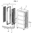
- Fig. 1 shows a server rack cooling structure.
- a cooling unit 1 is attached to the back of a server rack 9.
- the server rack 9 houses plural blade servers 91, for example, eight in total on its four shelves with two on each shelf.
- Each of the blade servers 91 is an electronic apparatus housing electronic components such as a CPU, memory, hard disk and power supply and blower fan where the power supply and memory are heat sources.
- the blower fan of each blade server takes in cooling air from ahead of the blade server or apparatus (direction indicated by arrow A) and discharges the air heated therein (hot air) through the back of the apparatus (exhaust ventilation side) to the outside of the apparatus (direction indicated by arrow B).
- the server rack 9 may have a conventional structure. Originally the conventional server rack 9 had a back door which can be opened and closed for maintenance of the servers, in place of the cooling unit 1. In other words, an outstanding feature of the present invention may be that the back door of the conventional server rack is removed and replaced by a back door with a novel cooling unit 1. If the server rack 9 is a new model, the cooling unit 1 according to this embodiment is an integral part thereof.
- the cooling unit 1 includes a radiator unit 11 for removing the heat from hot air discharged from the back of the rack; a fan unit 13 having many fans (for example, 36 fans or 12 rows by 3 columns) for forcibly discharging hot air; and a frame unit 12 to which the radiator unit 11 and fan unit 13 are integrally attached. That is, the integrally structured cooling unit 1 is constructed as a back door of the server rack 9. Details of these units will be described later referring to Figs. 2 to 8 .
- the radiator unit 11 has an array of pipes through which coolant (for example, water) circulates.
- Hoses 81 and 82 through which coolant is passed are connected to ends of the pipes.
- the structure of the cooling unit 1 will be described in detail referring to Figs. 2 to 8 .
- the frame unit 12 with the radiator unit 11 and fan unit 13 integrally attached thereto constructs a back door for cooling which is attached to the server rack 1 located on the right as viewed in Fig. 2 .
- a view taken from the right (server rack) side in Fig. 2 is referred to as a front view (for example, Fig. 4 ) and a view taken from the left side in Fig. 2 is referred to as a back view ( Figs. 5 , 6 , and 7 ).
- the frame unit 12 includes a radiator unit housing frame 31 for housing and holding the radiator unit 11 and a fan frame housing frame 32 for housing and holding the fan unit 13.
- the radiator unit housing frame 31 should have enough thickness W1 to house the radiator unit 11 (thickness W1') and the fan frame housing frame 32 should have enough thickness W2 to house the fan unit 13 (thickness W2').
- the radiator unit housing frame 31 has four recesses 311 to align with engaging points 225 in frames 1101 and 1102 of the radiator unit 11, and four screw holes 312 for fixing the radiator unit 11 with screws.
- the fan frame housing frame 32 has, for example, six screwing points 36 on the right and left for fixing the fan unit 13 with screws.
- the frame unit 12 includes hinges 35 to attach the back door, an integrated combination of the radiator unit 11 and fan unit 13, to the back of the server rack 9 in an openable and closable manner.
- the back door attached to the server rack 9 can be opened and closed using a knob 37.
- the frame unit 12 is provided with a typical lock mechanism (not shown) and service personnel for the server rack 9 is only allowed to unlock the lock mechanism and open the back door when necessary.
- the radiator unit 11 has a protective panel 21 facing the server rack 9 and a pipe assembly 22 ( Fig. 3 ) located on the inside thereof which are fixed in the frames 1101 and 1102 of the radiator unit 11.
- the protective panel 21, intended to protect the pipe assembly 22, is an aluminum plate with many slits on a surface thereof.
- the hot air discharged from the server rack 9 flows through the slits in the protective panel 21 to the pipe assembly 22.
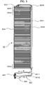
- Figs. 3 to 5 show the structure of the pipe assembly of the radiator unit 11.
- Figs. 4 and 5 illustrate the pipe assembly fixed in the frames 1101 and 1102 of the radiator unit 11 (the protective panel 21 is not shown).
- the main component of the radiator unit 11 is the pipe assembly 22 as a cluster of folded pipes.
- the pipe assembly 22 includes a pair of lower pipes 221 for circulation of coolant, a pair of vertical pipes 2221 and 2222 which are connected to the lower pipes 221 and vertically disposed, upper pipes 2231 and 2232 connected to the vertical pipes 2221 and 2222, and horizontal pipes 224 which are connected to the vertical pipes 2221 and 2222 respectively and zigzag-folded and disposed horizontally.
- the lower pipe 2211, vertical pipe 2221, and upper pipe 2231 are inflow pipes which allow coolant before heat absorption to flow in the direction indicated by arrow C1.
- the lower pipe 2212, vertical pipe 2222, and upper pipe 2232 are outflow pipes which allow coolant after heat absorption to flow in the direction indicated by arrow C2.
- the other ends of the lower pipes 221 are connected to a heat exchanger 86 through hoses ( Fig. 10 ).
- the coolant in the outflow pipe 2212 which has absorbed heat flows to the heat exchanger 86, thereby constituting a cooling system with coolant circulation.
- the pipe assembly 22 is mainly constructed of horizontal pipes 224 as a cluster of pipes and it may be said that the horizontal pipes 224 produce a cooling effect.
- the horizontal pipes 224 are a pipe cluster having plural horizontal pipe sets 2241 to 224n, each set having three folded pipes. These horizontal pipe sets 2241 to 224n are disposed vertically along the vertical pipes 2221 and 2222 and the pipe ends of each horizontal pipe set are welded to the vertical pipes to construct the pipe assembly 22.
- the horizontal pipe set 224n has plural pipes 2240 passing through holes in many rectangular fins 231 in a row with neighboring U-folded ends of the pipes 2240 welded to each other, thereby constituting a single horizontal pipe.
- One end 22401 of the pipes 2240 is connected to the vertical pipe 2221 and another end 22402 is connected to the vertical pipe 2222.
- the fins 231 are made of aluminum which is effective in heat radiation and hot air passes through slits 232 made between fins 231.
- the pipe assembly 22 is fitted in the frames 1101 and 1102 by fixing clamps on appropriate points of the pipes (vertical pipes 222*, upper pipes 223*, horizontal pipes 224*).
- the fins 231 are omitted and in Figs. 4 and 5 , the fins 231 are represented by vertical lines.
- a lot of rectangular slits 232 are formed by the fins 231 of the pipe assembly 22 in the radiator unit 11.
- the fins 231 guide hot air discharged from the server rack 9 toward the pipe assembly 22 by rotation of fans 43 and further guide the hot air passed through the pipe assembly 22 toward the fan unit 13.
- the fins 231 and slits 232 thus form flow channels for hot air and increase the efficiency of heat absorption by coolant circulating in the pipe assembly 22.
- Joints 261 and 262 are fixed to ends of the lower pipes 2211 and 2212 respectively.
- a hose 81 for circulation of coolant from the heat exchanger 86 ( Fig. 10 ) is connected to the joint 261 and a hose 82 which sends the coolant having absorbed heat to the heat exchanger 86 is connected to the joint 262.
- An opening/closing lever 27 is provided on the joint 261 to control circulation of the coolant sent through the hose 81.
- the length, width and thickness W1' of the radiator unit 11 are such that the radiator unit 11 fits in the radiator unit housing frame 31 of the frame unit 12.
- Convex tabs 225 as hooks to be engaged with the recesses 311 of the frame unit 12 are provided, for example, at four places on the rim of the radiator unit 11. These tabs 225 engage with the recesses 311 to fix the radiator unit 11 in the radiator unit housing frame 31 of the frame unit 12.
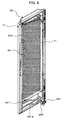
- Fig. 8 illustrates the radiator unit 11 fixed in the frame unit 12.
- the protective panel 21 of the radiator unit 11 and the fins 231 of the pipe assembly 22 are omitted so that the inside of the pipe assembly 22 is visible.
- the fan unit 13 has an iron fan frame 41 which is divided into thirty-six boxes 42 (twelve rows by three columns), with a fan 43 placed in each box 42.
- the fan frame 41 may include an upper frame 42 and a lower frame 42 which are bonded to each other where eighteen boxes (six rows by three columns) are formed in each of the upper and lower frames.
- Plural screwing points 46 are provided on the rim of the fan frame 41 to screw the fan unit 13 on mounting points 36 of the frame unit 12.
- the length, width and thickness W2' of the fan frame 41 are such that the fan frame 41 fits in the fan frame housing frame 32 of the frame unit 12.
- the screwing points 36 and mounting points 46 are respectively joined by screwing.
- Power cords for power supply to the fans 43 are embedded inside the fan frame 41, though invisible in the figure.
- Fig. 10 shows an example of a server rack cooling system configuration.
- two server racks 9 each having a cooling unit 1 are installed in a server room.
- the server room has a free-access floor 99 and hoses 81 and 82 for circulation of coolant are laid under the floor 99 with one end of each hose connected through a pump 85 to a heat exchanger 86 installed outdoors.
- the pump 85 is run to force coolant to circulate.
- the heat exchanger 86 is an AC (Air Chiller) heat exchanger or AW (Air Water) heat exchanger. If an AC heat exchanger as illustrated is employed, the pump 85 is installed midway on the hose 81 for circulation of coolant and coolant is forced to circulate by operation of the pump. The AC heat exchanger 86 releases the heat of the coolant in the direction indicated by arrows W by rotation of the fan. The AC heat exchanger is expected to produce a cooling effect which is strong enough to cool plural racks at a time.
- the AW heat exchanger can be installed in the same room where the server racks to be cooled are installed, though its cooling ability is slightly lower than that of the AC heat exchanger. Since the AW system eliminates the need for outdoor installation work, it is easier to introduce the cooling system than when the AC heat exchanger is employed.
- both the AC system and AW system can use the same cooling unit 1, even when the AW cooling system is initially employed, it can be easily replaced by the AC system later in order to increase the cooling capacity.
- the AW heat exchanger 86 should be replaced by the AC heat exchanger.
- hoses 81' and 82' are connected to the new server rack and the other ends of the hoses are connected to the common hoses 81 and 82.
- a cooling system with a higher cooling efficiency can be constructed by removing the back door of a conventional server rack and replacing it by a back door as a cooling unit according to this embodiment.
- the cooling system can be constructed while the servers are in operation.
- the size of the back door as a cooling unit can be freely changed depending on the size of the server rack to which it is attached. It is also possible to change the number of fans 43 in the fan unit 13 depending on the amount of heat generated by servers. Further, the AW system or AC system can be selected according to the amount of heat generated by servers inside the server rack or the number or capacity of servers installed in the server room. Also, even in the same cooling system, it is possible to cope with change in the number or capacity of servers by altering the heat exchanger capacity.
- the present invention is not limited to the above embodiment but it may be embodied in various other forms.
- the cooling unit is used for the back door of the server rack, but it is not limited thereto. If an electronic apparatus rack is designed to discharge hot air inside it through its top surface or lateral surface, the cooling unit according to this embodiment can be attached to the top or lateral surface. If it is attached to the top surface and need not be openable, it may be attached in a fixed manner.
- the radiator unit 11 and the fan unit 13 are integrally fitted in the frame unit 12.
- the frame unit 12 may not be a separate unit.
- the fan frame 41 as the outer frame of the fan unit 13 may be a sturdy structure or a fan frame designed to hold and fix the fan unit instead of the frame unit. Also, if a sturdy frame-like structure for holding and fixing the radiator unit 11 is provided, the structure may be used as the frame unit 12.
- the number of fans 43 in the fan unit 13 may be varied as needed. In the case of a large server rack, more fans may be needed and the fan unit 13 shown in Fig. 7 may be larger.
- the arrangement and number of fans 43 in the fan unit 13 may be varied as needed. If four blade servers are mounted only on the two upper shelves of the server rack 9 shown in Fig. 1 , the fan unit 13 need not have as many fans 43 as required to cover the whole back surface of the rack 9 but it may be sufficient that it has only as many fans 43 as required to cover the blade absorbers on the two upper shelves.
- the cooling unit is applied to server racks which house blade servers.
- it may also be applied to electronic apparatus racks housing electronic apparatuses with heat sources such as disk array devices housing may disk units or communication racks housing plural communication devices.
Landscapes
- Engineering & Computer Science (AREA)
- Physics & Mathematics (AREA)
- Thermal Sciences (AREA)
- Microelectronics & Electronic Packaging (AREA)
- General Engineering & Computer Science (AREA)
- Computer Hardware Design (AREA)
- Mechanical Engineering (AREA)
- Computer Networks & Wireless Communication (AREA)
- Signal Processing (AREA)
- Cooling Or The Like Of Electrical Apparatus (AREA)
Applications Claiming Priority (1)
| Application Number | Priority Date | Filing Date | Title |
|---|---|---|---|
| JP2008205804A JP2010041007A (ja) | 2008-08-08 | 2008-08-08 | 冷却ユニット、電子装置ラック、冷却システム及びその構築方法 |
Publications (1)
| Publication Number | Publication Date |
|---|---|
| EP2152054A2 true EP2152054A2 (fr) | 2010-02-10 |
Family
ID=41264260
Family Applications (1)
| Application Number | Title | Priority Date | Filing Date |
|---|---|---|---|
| EP09002775A Withdrawn EP2152054A2 (fr) | 2008-08-08 | 2009-02-26 | Unité de refroidissement, bâti d'appareil électronique, système de refroidissement et procédé de construction associé |
Country Status (4)
| Country | Link |
|---|---|
| US (1) | US20100033931A1 (fr) |
| EP (1) | EP2152054A2 (fr) |
| JP (1) | JP2010041007A (fr) |
| KR (1) | KR20100019308A (fr) |
Cited By (3)
| Publication number | Priority date | Publication date | Assignee | Title |
|---|---|---|---|---|
| WO2012055959A1 (fr) * | 2010-10-29 | 2012-05-03 | International Business Machines Corporation | Centre de données refroidi par liquide comprenant des conduites d'arrivée d'agent réfrigérant |
| CN107613732A (zh) * | 2017-09-28 | 2018-01-19 | 深圳兴奇宏科技有限公司 | 机箱散热结构 |
| EP3648561A1 (fr) * | 2018-10-29 | 2020-05-06 | Quanta Computer Inc. | Refroidissement de liquide avec système de crémaillère de refroidisseur extérieur |
Families Citing this family (50)
| Publication number | Priority date | Publication date | Assignee | Title |
|---|---|---|---|---|
| CA2504222C (fr) | 2002-10-22 | 2012-05-22 | Jason A. Sullivan | Ordinateur robuste et personnalisable |
| EP1557075A4 (fr) | 2002-10-22 | 2010-01-13 | Sullivan Jason | Module de controle non associe aux peripheriques possedant des proprietes ameliorees de dissipation de chaleur |
| CA2503793A1 (fr) | 2002-10-22 | 2004-05-06 | Jason A. Sullivan | Systemes et procedes d'elaboration d'une unite de traitement dynamiquement modulaire |
| FR2931961B1 (fr) | 2008-06-02 | 2010-06-11 | Bull Sas | Dispositif de refroidissement d'une baie informatique et installation informatique comportant un tel dispositif |
| TW201221036A (en) * | 2010-11-05 | 2012-05-16 | Inventec Corp | Server rack |
| TWI392997B (zh) * | 2010-11-05 | 2013-04-11 | Inventec Corp | 伺服器之冷卻循環系統 |
| TWI392432B (zh) | 2010-11-23 | 2013-04-01 | Inventec Corp | 一種伺服器機櫃 |
| CN102478935A (zh) * | 2010-11-29 | 2012-05-30 | 英业达股份有限公司 | 机架式服务器系统 |
| JP2012118781A (ja) | 2010-12-01 | 2012-06-21 | Hitachi Ltd | 電子機器用ラックおよびデータセンタ |
| CN102736688B (zh) * | 2011-04-13 | 2014-12-10 | 英业达股份有限公司 | 伺服器机架系统 |
| CN102736706B (zh) * | 2011-04-13 | 2015-07-01 | 英业达股份有限公司 | 伺服器机架系统 |
| JP5750304B2 (ja) * | 2011-05-18 | 2015-07-22 | 株式会社日立製作所 | 電子機器の冷却システム |
| DE112011105140T5 (de) * | 2011-05-25 | 2014-01-09 | Hewlett-Packard Development Company, L.P. | Blade-Computersystem |
| GB2493324A (en) * | 2011-05-27 | 2013-02-06 | Semper Holdings Ltd | Cooling System with heat-exchanger mounted within a server cabinet |
| JP6002369B2 (ja) * | 2011-06-27 | 2016-10-05 | 株式会社Nttファシリティーズ | サーバラック冷却装置 |
| KR101233786B1 (ko) * | 2011-07-20 | 2013-02-15 | 아이스파이프 주식회사 | 시설물 과열 및 동결 방지장치 |
| WO2013030979A1 (fr) * | 2011-08-31 | 2013-03-07 | 富士通株式会社 | Système de climatisation et échangeur de chaleur |
| US20130075058A1 (en) * | 2011-09-22 | 2013-03-28 | Mu-Chang Kang | Cooling cabinet |
| US8817474B2 (en) | 2011-10-31 | 2014-08-26 | International Business Machines Corporation | Multi-rack assembly with shared cooling unit |
| US8760863B2 (en) | 2011-10-31 | 2014-06-24 | International Business Machines Corporation | Multi-rack assembly with shared cooling apparatus |
| US20130308266A1 (en) * | 2011-11-10 | 2013-11-21 | Jason A. Sullivan | Providing and dynamically mounting and housing processing control units |
| CN103188909A (zh) * | 2011-12-29 | 2013-07-03 | 英业达股份有限公司 | 机架结构 |
| WO2013119243A1 (fr) | 2012-02-09 | 2013-08-15 | Hewlett-Packard Development Company, L.P. | Système de dissipation thermique |
| EP2826347B1 (fr) * | 2012-03-12 | 2017-10-25 | Hewlett-Packard Enterprise Development LP | Refroidissement à régulation de température de liquide |
| WO2013137849A1 (fr) * | 2012-03-12 | 2013-09-19 | Hewlett-Packard Development Company, L.P. | Système de refroidissement de baie avec une section de refroidissement |
| US9016352B2 (en) * | 2012-05-21 | 2015-04-28 | Calvary Applied Technologies, LLC | Apparatus and methods for cooling rejected heat from server racks |
| EP2901828A4 (fr) | 2012-09-28 | 2016-06-01 | Hewlett Packard Development Co | Ensemble de refroidissement |
| TW201422130A (zh) * | 2012-11-23 | 2014-06-01 | Hon Hai Prec Ind Co Ltd | 數據中心及其伺服器機櫃 |
| DE102012112507B3 (de) * | 2012-12-18 | 2014-06-18 | Rittal Gmbh & Co. Kg | Schaltschrank mit schwenkbarem Wärmetauscher |
| WO2014120182A1 (fr) | 2013-01-31 | 2014-08-07 | Hewlett-Packard Development Company, L.P. | Refroidissement de liquide |
| JP2014183175A (ja) * | 2013-03-19 | 2014-09-29 | Toshiba Corp | 放熱器 |
| WO2015072128A1 (fr) | 2013-11-14 | 2015-05-21 | 日本電気株式会社 | Structure de tuyauterie, dispositif de refroidissement l'utilisant et procédé de transport de vapeur de réfrigérant |
| US10201116B1 (en) * | 2013-12-02 | 2019-02-05 | Amazon Technologies, Inc. | Cooling system for data center rack |
| KR200477833Y1 (ko) * | 2014-05-02 | 2015-07-28 | 매니코어소프트주식회사 | 냉각장치 |
| KR101627692B1 (ko) | 2015-04-01 | 2016-06-07 | 주식회사 성신테크 | 슬라이딩 자동문 밀폐장치 |
| US9832912B2 (en) * | 2015-05-07 | 2017-11-28 | Dhk Storage, Llc | Computer server heat regulation utilizing integrated precision air flow |
| CN104866040A (zh) * | 2015-06-12 | 2015-08-26 | 苏州圣谱拉新材料科技有限公司 | 一种新型的水帘散热机箱 |
| JP6034465B1 (ja) * | 2015-10-15 | 2016-11-30 | Necプラットフォームズ株式会社 | 冷却装置及び冷却システム |
| DE202017100139U1 (de) * | 2017-01-12 | 2017-06-23 | Vacon Oy | Türkühler |
| KR102034552B1 (ko) | 2017-12-22 | 2019-10-21 | 주식회사 씨엔씨알 | 서버랙의 비상 보호장치 |
| US10893633B2 (en) * | 2018-11-13 | 2021-01-12 | Modine Manufacturing Company | Method of cooling an electronics cabinet |
| CN110461133A (zh) * | 2019-08-21 | 2019-11-15 | 香江科技股份有限公司 | 适用于bbu设备集中池化的冷却机柜 |
| US12575066B2 (en) | 2021-03-11 | 2026-03-10 | Core Scientific, Inc. | System for cooling computing devices in an array |
| US11751361B2 (en) * | 2021-06-02 | 2023-09-05 | Microsoft Technology Licensing, Llc | Systems and methods for datacenter thermal management |
| CN113438842B (zh) * | 2021-06-25 | 2022-07-08 | 安庆船用电器有限责任公司 | 一种柴油机用水冷式电气控制箱 |
| CA3189830A1 (fr) * | 2022-02-18 | 2023-08-18 | Dantherm Cooling, Inc. | Grille d'aeration auxiliaire pour une unite de regulation du climat |
| CN217509346U (zh) * | 2022-03-16 | 2022-09-27 | 广运机械工程股份有限公司 | 热交换系统 |
| CN115066167A (zh) * | 2022-08-17 | 2022-09-16 | 湖南第一师范学院 | 一种计算机机房空气调节系统 |
| EP4373231A1 (fr) * | 2022-11-17 | 2024-05-22 | Bull Sas | Extension d'armoire de supercalculateur |
| KR102847084B1 (ko) * | 2022-11-24 | 2025-08-18 | 주식회사 삼화에이스 | 데이터센터의 서버랙 냉각유닛 |
Citations (2)
| Publication number | Priority date | Publication date | Assignee | Title |
|---|---|---|---|---|
| JP2004063755A (ja) | 2002-07-29 | 2004-02-26 | Fujitsu Ltd | ラック冷却構造 |
| JP2006093388A (ja) | 2004-09-24 | 2006-04-06 | Nihon Form Service Co Ltd | サーバーラック用冷却装置 |
-
2008
- 2008-08-08 JP JP2008205804A patent/JP2010041007A/ja active Pending
-
2009
- 2009-02-26 US US12/393,320 patent/US20100033931A1/en not_active Abandoned
- 2009-02-26 KR KR1020090016079A patent/KR20100019308A/ko not_active Ceased
- 2009-02-26 EP EP09002775A patent/EP2152054A2/fr not_active Withdrawn
Patent Citations (2)
| Publication number | Priority date | Publication date | Assignee | Title |
|---|---|---|---|---|
| JP2004063755A (ja) | 2002-07-29 | 2004-02-26 | Fujitsu Ltd | ラック冷却構造 |
| JP2006093388A (ja) | 2004-09-24 | 2006-04-06 | Nihon Form Service Co Ltd | サーバーラック用冷却装置 |
Cited By (8)
| Publication number | Priority date | Publication date | Assignee | Title |
|---|---|---|---|---|
| WO2012055959A1 (fr) * | 2010-10-29 | 2012-05-03 | International Business Machines Corporation | Centre de données refroidi par liquide comprenant des conduites d'arrivée d'agent réfrigérant |
| US8531839B2 (en) | 2010-10-29 | 2013-09-10 | International Business Machines Corporation | Liquid cooled data center with alternating coolant supply lines |
| GB2499158B (en) * | 2010-10-29 | 2014-08-20 | Ibm | Liquid cooled data center with coolant supply lines |
| US9258931B2 (en) | 2010-10-29 | 2016-02-09 | International Business Machines Corporation | Liquid cooled data center with alternating coolant supply lines |
| CN107613732A (zh) * | 2017-09-28 | 2018-01-19 | 深圳兴奇宏科技有限公司 | 机箱散热结构 |
| CN107613732B (zh) * | 2017-09-28 | 2024-06-07 | 深圳兴奇宏科技有限公司 | 机箱散热结构 |
| EP3648561A1 (fr) * | 2018-10-29 | 2020-05-06 | Quanta Computer Inc. | Refroidissement de liquide avec système de crémaillère de refroidisseur extérieur |
| US11147191B2 (en) | 2018-10-29 | 2021-10-12 | Quanta Computer Inc. | Liquid cooling with outdoor chiller rack system |
Also Published As
| Publication number | Publication date |
|---|---|
| US20100033931A1 (en) | 2010-02-11 |
| KR20100019308A (ko) | 2010-02-18 |
| JP2010041007A (ja) | 2010-02-18 |
Similar Documents
| Publication | Publication Date | Title |
|---|---|---|
| EP2152054A2 (fr) | Unité de refroidissement, bâti d'appareil électronique, système de refroidissement et procédé de construction associé | |
| JP6223519B2 (ja) | サーバファーム冷却システムのための冷気列封入 | |
| US8593815B2 (en) | Techniques for data center cooling | |
| US6506111B2 (en) | Cooling airflow distribution device | |
| EP2171385B1 (fr) | Système de refroidissement auxiliaire | |
| JP6046093B2 (ja) | サーバファーム冷却システムのための冷気列封入 | |
| US8764528B2 (en) | Systems and methods for closed loop heat containment with cold aisle isolation for data center cooling | |
| US10588245B2 (en) | Assembly for extracting heat from a housing for electronic equipment | |
| US8031468B2 (en) | Hot aisle containment cooling unit and method for cooling | |
| AU2009338698B2 (en) | Hot aisle containment cooling system and method | |
| US20100248609A1 (en) | Assembly For Providing A Downflow Return Air Supply | |
| US20090122483A1 (en) | Water-assisted air cooling for a row of cabinets | |
| TW201408182A (zh) | 貨櫃數據中心 | |
| US9723760B2 (en) | Water-assisted air cooling for a row of cabinets | |
| US20150267931A1 (en) | Split air-conditioner module | |
| US11116111B2 (en) | Method and arrangement for air-conditioning a cold aisle | |
| JP2010267841A (ja) | 冷却ユニット、冷却構造及び冷却システムの構築方法 | |
| CN206977886U (zh) | 一种机柜顶置式换热装置 | |
| CN210868579U (zh) | 一种利用水冷技术的仪器密封机柜系统 | |
| EP3289844B1 (fr) | Cadre profilé pour unité de conditionnement d'air de salle des ordinateurs | |
| CN216532290U (zh) | 适用于多场景的可调式散热装置 | |
| CN120320190A (zh) | 一种电力配电箱 |
Legal Events
| Date | Code | Title | Description |
|---|---|---|---|
| PUAI | Public reference made under article 153(3) epc to a published international application that has entered the european phase |
Free format text: ORIGINAL CODE: 0009012 |
|
| AK | Designated contracting states |
Kind code of ref document: A2 Designated state(s): AT BE BG CH CY CZ DE DK EE ES FI FR GB GR HR HU IE IS IT LI LT LU LV MC MK MT NL NO PL PT RO SE SI SK TR |
|
| AX | Request for extension of the european patent |
Extension state: AL BA RS |
|
| 17P | Request for examination filed |
Effective date: 20100211 |
|
| STAA | Information on the status of an ep patent application or granted ep patent |
Free format text: STATUS: THE APPLICATION HAS BEEN WITHDRAWN |
|
| 18W | Application withdrawn |
Effective date: 20100409 |
|
| RIN1 | Information on inventor provided before grant (corrected) |
Inventor name: EBATO, TSUYOSHI Inventor name: IETA, KANAME Inventor name: IWATA, HIROSHI Inventor name: ARAYA, TAKESHI Inventor name: MIYAZAWA, TOMOYUKI |