EP2153193B1 - Verfahren und system zur fernüberwachung von deformationen einer struktur - Google Patents
Verfahren und system zur fernüberwachung von deformationen einer struktur Download PDFInfo
- Publication number
- EP2153193B1 EP2153193B1 EP08737580A EP08737580A EP2153193B1 EP 2153193 B1 EP2153193 B1 EP 2153193B1 EP 08737580 A EP08737580 A EP 08737580A EP 08737580 A EP08737580 A EP 08737580A EP 2153193 B1 EP2153193 B1 EP 2153193B1
- Authority
- EP
- European Patent Office
- Prior art keywords
- electromagnetic field
- rfid tags
- measurements
- deformations
- points
- Prior art date
- Legal status (The legal status is an assumption and is not a legal conclusion. Google has not performed a legal analysis and makes no representation as to the accuracy of the status listed.)
- Not-in-force
Links
- 238000000034 method Methods 0.000 title claims abstract description 29
- 238000012544 monitoring process Methods 0.000 title claims abstract description 20
- 230000005672 electromagnetic field Effects 0.000 claims abstract description 64
- 238000005259 measurement Methods 0.000 claims abstract description 40
- 238000006073 displacement reaction Methods 0.000 claims abstract description 10
- 230000004044 response Effects 0.000 claims abstract description 6
- 238000012545 processing Methods 0.000 claims description 10
- 230000008878 coupling Effects 0.000 claims description 7
- 238000010168 coupling process Methods 0.000 claims description 7
- 238000005859 coupling reaction Methods 0.000 claims description 7
- 230000001427 coherent effect Effects 0.000 claims 1
- 230000036541 health Effects 0.000 description 4
- 230000005855 radiation Effects 0.000 description 4
- 230000008901 benefit Effects 0.000 description 3
- 230000008859 change Effects 0.000 description 3
- 238000004891 communication Methods 0.000 description 3
- 230000007613 environmental effect Effects 0.000 description 3
- 230000006870 function Effects 0.000 description 3
- 230000035882 stress Effects 0.000 description 3
- 238000009826 distribution Methods 0.000 description 2
- 239000000463 material Substances 0.000 description 2
- 230000032683 aging Effects 0.000 description 1
- 230000006399 behavior Effects 0.000 description 1
- 238000006243 chemical reaction Methods 0.000 description 1
- 238000001514 detection method Methods 0.000 description 1
- 238000005516 engineering process Methods 0.000 description 1
- 230000004807 localization Effects 0.000 description 1
- 210000003205 muscle Anatomy 0.000 description 1
- 239000013307 optical fiber Substances 0.000 description 1
- 239000000523 sample Substances 0.000 description 1
- 238000012360 testing method Methods 0.000 description 1
- 238000012546 transfer Methods 0.000 description 1
- 230000009466 transformation Effects 0.000 description 1
- 238000013519 translation Methods 0.000 description 1
Images
Classifications
-
- G—PHYSICS
- G01—MEASURING; TESTING
- G01M—TESTING STATIC OR DYNAMIC BALANCE OF MACHINES OR STRUCTURES; TESTING OF STRUCTURES OR APPARATUS, NOT OTHERWISE PROVIDED FOR
- G01M5/00—Investigating the elasticity of structures, e.g. deflection of bridges or air-craft wings
- G01M5/0091—Investigating the elasticity of structures, e.g. deflection of bridges or air-craft wings by using electromagnetic excitation or detection
-
- G—PHYSICS
- G01—MEASURING; TESTING
- G01M—TESTING STATIC OR DYNAMIC BALANCE OF MACHINES OR STRUCTURES; TESTING OF STRUCTURES OR APPARATUS, NOT OTHERWISE PROVIDED FOR
- G01M5/00—Investigating the elasticity of structures, e.g. deflection of bridges or air-craft wings
- G01M5/0041—Investigating the elasticity of structures, e.g. deflection of bridges or air-craft wings by determining deflection or stress
Definitions
- the present invention relates to a method and to a system for remote monitoring deformations of a structure.
- the present invention is advantageously, but not exclusively intended for use in the field of monitoring the state of health of structures under stress such a building, a bridge or structural parts of a means of transport or a generic machinery, or parts of a living organism, for example, a muscle or a limb, to which the following description expressly refers without prejudice to the generality thereof.
- Radio-frequency resonant cavities whose resonant frequency depends on the size of the resonant cavity are well known. Such sensors are inserted in the stressed structural material to be monitored. When the material is subjected to a stress such as to alter the size of resonant cavity, the resonance frequency changes. Therefore, by processing the resonant frequency changes it is possible to trace the deformation of the structure.
- the sensor is typically equipped with a radio-frequency communication device, for example a RFID tag ("RFID tag”) (Radio Frequency IDentification), to receive a variable-frequency radio signal from a remote interrogator device, to transfer such a radio signal to the resonant cavity for exciting it and to transmit back the cavity reaction to the interrogator device. In this way it is possible to remotely interrogating the sensor without physical connection, that is "wirelessly”.
- RFID tag Radio Frequency IDentification
- the resonant-cavity sensors provide fairly reliable measurements, but have the disadvantage of being rather bulky, and therefore of being particularly invasive and difficult to be installed.
- piezoelectric sensors based on MEMS technology, which sensors convert the mechanical variation of the structures to which they are attached in electric signal changes. These sensors have the advantage of having reduced dimensions, compared to those based on resonant cavities, however at the expense of lower reliability. This type of sensors too is provided with a radio-frequency communication device to transmit the information coming from the sensor to the interrogator device.
- sensors are based on optical fiber Bragg gratings. Such sensors provide very accurate deformation measurements but are extremely expensive and bulky as well.
- Patent application WO 03/085360 describes a structural health monitoring system comprising sensor devices coupled to a structure to be monitored, each sensor device comprising a generic sensor capable of detecting a parameter indicative of the health of the structure and a wireless RFID transponder capable of storing information obtained by the sensor, and a wireless interrogator to probe the transponder of each sensor device to get information stored therein.
- Patent application US 2006/025897 describes a similar monitoring system for obtaining and providing a measurement of a physical quantity, e.g. measurement of temperature and/or pressure, of a vehicular tire.
- the purpose of present invention is to achieve a system for remote monitoring deformations of a structure under stress, which overcomes the drawbacks described above and, at the same time, is easy to use and cost-effective to implement.
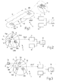
- number 1 generically indicates as a whole, the system for remote monitoring deformations of a structure 2.
- the depicted system 1 comprises two RFID tags 3 of known type, namely of the type comprising each a microchip 4 to store information related to the RFID tag 3, including its own identification code, and a miniaturized antenna 5 connected to the microchip 4 to receive and transmit radio signals at a prescribed operating frequency F; an interrogation unit 6 of known type designed to interrogate via radio signals at the operating frequency F the RFID tags 3; an electromagnetic-field measurement unit 7 to obtain measurements of a resultant electromagnetic field produced by the RFID tags 3 in response to said interrogation; and a processing unit 8 to control the interrogation unit 6 and the measurement unit 7 in order to acquire and store, through its own internal memory 9, electromagnetic field measurements and to determine deformations of the structure 2 based on the stored electromagnetic field measurements.
- Each RFID tag 3 is of active type, that is, electrically powered by its own battery (not shown), or of passive type, that is, electrically powered through the transformation of part of the radio frequency electromagnetic field received by the interrogation unit 6 during the interrogation.
- the two RFID tags 3 are designed to be coupled to the structure 2 in two points 10a e 10b of the structure itself, and to be positioned at a reference distance D from one another in order to monitor the deformations of a portion 11 of the structure 2 located between such points 10a and 10b.
- the RFID tags 3 may be coupled to the structure 2 through bonding, or by fastening with screws, or through appropriate interlocking shapes.
- the processing unit 8 is configured to implement the method for remote monitoring deformations of a structure described hereinafter.
- the method envisages to interrogate, through the interrogation unit 6, the RFID tags 3 so that a resultant electromagnetic field is produced at a certain distance DINF from a reference point 12 of the structure 2, such a resultant electromagnetic field ensuing from a combination of electromagnetic fields produced individually by each RFID tag 3 in response to the interrogation.
- the interrogation unit 6 sends one or more radio signals that excite both RFID tags 3 in such a way that they simultaneously produce respective electromagnetic fields, which have the same frequency and phase and thus interfere with each other coherently. Therefore, the two RFID tags 3 behave, from the electromagnetic point of view, as a phased antenna array of the broadside type.
- the interrogation envisages to send a radio signal at the operating frequency F modulated, according to procedures known from the RFID standards, with the identification codes of the two RFID tags 3, which simultaneously reply to the radio signal producing respective electromagnetic fields at the operating frequency F.
- the interrogation envisages to send, at different time slots, two radio signals at the operating frequency F, each modulated with the identification code of a respective of the RFID tags 3 and with information relating to a response delay associated to such RFID tag 3 so that the two RFID tags 3 can reply simultaneously producing respective electromagnetic fields at the operating frequency F.
- the resultant electromagnetic field exhibits amplitude and phase distributions, with respect to the angular coordinates (azimuth and elevation) of a polar coordinate system, which distributions have a defined dependence on the distance between points 10a and 10b.
- the distance DINF needs to satisfy the well known relationships: DINF > > ⁇ DINF > Lmax 2 / ⁇ , where Lmax is the largest linear dimension of the antenna 5 of the RFID tag 3 and ⁇ is the wavelength of the resultant electromagnetic field.
- the resultant electromagnetic field is measured, by the measurement unit 7 placed at the distance DINF from the reference point 12 of the structure 2, to obtain relative amplitude and/or phase measurements.
- the amplitude measurements of the resultant electromagnetic field are acquired by the processing unit 8 to build a portion of the radiation surface of the RFID tags 3 at the distance DINF as a function of the azimuth and elevation directions.
- Null directions are determined by means of such a radiation surface.
- the null radiations are the directions in which the electromagnetic field intensity is substantially equal to zero and which delimit the main lobe of the radiation surface.
- the angle between two null directions depends on the ratio between the distance between points 10a and 10b and the wavelength ⁇ of the resultant electromagnetic field, according to simple relationships, which are known from the electromagnetism theory.
- the phase measurements of the resultant electromagnetic field are acquired by the processing unit 8 to be used alternatively or in combination with the amplitude measurements.
- the resultant electromagnetic field phase depends on the ratio between the distance between points 10a and 10b and the wavelength ⁇ of the resultant electromagnetic field, according to simple relationships, which are known from the electromagnetism theory.
- the choice of the type of measurement to employ is made according to the quality of the radio channel involved.
- the electromagnetic field at the distance DINF is measured soon after coupling the RFID tags 3 to the structure 2 in order to have measurements of a reference resultant electromagnetic field, which in the following will be referred to as "reference electromagnetic field" for the sake of simplicity and which corresponds to a reference position of the points 10a and 10b defined by the reference distance D.
- the reference electromagnetic field measurements are stored in the internal memory 9.
- the electromagnetic field is measured each time the state of health of the structure 2 is required to be monitored, that is each time it is required to test whether the portion 11 has undergone deformations in terms of a mutual displacement between points 10a and 10b, and more specifically whether there has been a change of distance between points 10a and 10b with respect to the reference distance D.
- the subsequent measurements of the resultant electromagnetic field are then compared with the measurements of the reference electromagnetic field in order to establish possible variations of the resultant electromagnetic field.
- the variations of the distance between points 10a and 10b with respect to the reference distance D are determined as a function of variations of the resultant electromagnetic field on the basis of the above mentioned relationships.
- the accuracy in determining the deformations depends on the alleged order of magnitude of the deformations with respect to the wavelength ⁇ of the resultant electromagnetic field. Therefore, in order to measure deformations in the centimetre range the RFID tags 3 are preferably of the kind operating in the microwave band, such as those having an operating frequency F inside the 2,45 GHz band or inside the 5,8 GHz band. Similarly, in order to measure deformations in the millimetre range, the RFID tags 3 are preferably of the kind operating at millimetre-wave frequencies.
- Figure 2 illustrates a second embodiment of the present invention.
- the second embodiment differs from that of figure 1 in that the system 1 comprises more than two RFID tags 3, and in particular three RFID tags 3 designed to be coupled to the structure 2 at respective not-aligned points of it, which points are referred to as 10a, 10b, 10c and are positioned at relative reference distances Dab, Dac, Dbc from each other.
- the reference distances Dab, Dac and Dbc define a reference arrangement of the points 10a, 10b and 10c.
- the method for remote monitoring deformations of a structure implemented by the processing unit 8 envisages to interrogate the RFID tags 3 in pairs and to measure the resultant electromagnetic field produced by each interrogation of RFID tag 3 in pairs.
- the interrogation is carried out at least for one of the combinations without repetition of a pair of RFID tags 3, that is, the two RFID tags 3 fixed in points 10a and 10b, and/or those fixed in points 10a and 10c, and/or those fixed in points 10b and 10c.
- a system 1 comprising more than three RFID tag 3 is basically a generalisation of the system 1 having two or three RFID tags 3 that can be used to obtain more detailed information on deformations of wider portions 11 of the structure 2 to be monitored, possibly by means of triangulation techniques.
- the system 1 comprises a further RFID tag 3 positioned in a reference point 13 outside the structure 2 and considered fixed with respect to possible deformations or displacements of the structure 2.
- the RFID tags 3 that are coupled to the structure 2 in points 10a, 10b and 10c result to be positioned at respective reference distances Da Db Dc from the reference point 13.
- the method for remote monitoring deformations of the structure implemented by the processing unit 8 according to the third embodiment envisages to interrogate pairs of RFID tags 3, each pair comprising the RFID tag 3 positioned in the reference point 13 in order to determine the displacements of points 10a 10b and 10c with respect to the reference point 13, that is the variations of the distances of points 10a 10b and 10c from the reference point 13 with respect to the reference distances Da, Db and Dc.
- This makes it possible to monitor, beside the deformation of portion 11 of the structure 2, any rigid roto-translations of the portion 11 with respect to the reference point 13. From the above it is understood that the functioning of the system 1 according to the third embodiment will not change in case the system 1 comprises two or more than three RFID tags 3.
- the system 1 presents another possible use of the system 1. Indeed, the underlying concept of the present invention, that is the ability to remotely monitor variations of distances between any two points in the space by interrogating two RFID tags 3 associated to these points in the way previously described and by measuring the resultant electromagnetic field produced by these sources, permits to use the system 1 as a system for remote monitoring displacements of the points 10a, 10b, and 10c of the structure 2 with respect to one of them, as for example point 10a, or with respect to an external reference point 13, with an accuracy within one millimetre.
- the system 1 implements a function of fine localization of objects, or parts of a same object or structure, which objects or parts of an object a coupled to respective RFID tags 3.
- each pair of RFID tags 3 constitutes both the deformation sensor and the communication device used to transmit the information acquired by the sensor to the interrogation unit 6. This results, firstly, in much lower costs with respect to existing solutions.
- the very limited size and weight of the RFID tags 3 allow to attach the RFID tag 3 to any structure 2, for instance to a sail of a boat, to a body shell of a car, or into an artificial limb, thus broadening the fields of application of the system 1.
- the system 1 works without straining the deformation sensor, which consists of two or three RFID tags 3, and this results in a further twofold advantage.
- the deformation sensor which consists of two or three RFID tags 3, and this results in a further twofold advantage.
- the system 1 provides measurements substantially independent of any changes in environmental parameters, such as the humidity of the air and in particular the temperature, as well as possible variations of the RFID tags 3 behaviour, for example due to aging or exposure to the environment, since the null directions of the field depend exclusively on the array factor, and thus on the ratio between the distance between the RFID tags 3 and the wavelength ⁇ . Therefore the system 1 does not require nor complex and delicate calibration procedures for compensating variations of the environmental parameters, nor the detection of values of the same. On the contrary, the environmental conditions may directly affect the results provided by sensors known so far, which need to be calibrated appropriately. As an example, a temperature variation always originates variations of the size of a resonant cavity and thus of its own resonance frequency, that could be erroneously understood as due to a deformation of the structure 2.
Landscapes
- Physics & Mathematics (AREA)
- Engineering & Computer Science (AREA)
- Aviation & Aerospace Engineering (AREA)
- General Physics & Mathematics (AREA)
- Electromagnetism (AREA)
- Arrangements For Transmission Of Measured Signals (AREA)
- Measurement Of Length, Angles, Or The Like Using Electric Or Magnetic Means (AREA)
- Length-Measuring Devices Using Wave Or Particle Radiation (AREA)
- Crystals, And After-Treatments Of Crystals (AREA)
Claims (15)
- Verfahren zur Fernüberwachung von Deformationen einer Struktur (2), wobei das Verfahren Folgendes aufweist:- Koppeln von wenigstens zwei RFID Etiketten (3) an die Struktur (2) an entsprechenden Punkten (10a, 10b; 10a-10c) der Struktur (2) selbst;das Verfahren ist dadurch gekennzeichnet dass es Folgendes aufweist:- Abfragen der RFID Etiketten (3) mit einer Hochfrequenz, so dass ein resultierendes elektromagnetisches Feld in einer bestimmten Entfernung (DINF) von der Struktur (2) erzeugt wird, wobei sich das resultierende elektromagnetische Feld aus einer Kombination der elektromagnetischen Felder ergibt, die singulär von den RFID Etiketten (3) als Antwort auf die Abfrage erzeugt wurden;- Messen des elektromagnetischen Feldes in dem bestimmten Abstand (DINF) um Messungen des resultierenden elektromagnetischen Feldes zu erhalten; und- Bestimmen der Deformationen der Struktur (2), als Funktion der Messungen des resultierenden elektromagnetischen Feldes.
- Verfahren gemäß Anspruch 1, wobei das Koppeln von wenigstens zwei RFID Etiketten (3) an die Struktur (2) das Koppeln von wenigstens drei RFID Etiketten (3) an die Struktur (2) an jeweiligen Punkten (10a-10c) der Struktur selbst aufweist; Abfragen der RFID Etiketten (3) mit einer Hochfrequenz weist das Abfragen der RFID Etiketten (3) in Paaren auf; Messen des elektromagnetischen Feldes in dem bestimmten Abstand (DINF) beinhaltet das Messen des elektromagnetischen Feldes um Messungen des resultierenden elektromagnetischen Feldes zu erhalten, die durch die Abfrage der RFID Etiketten (3) in Paaren erzeugt wurden.
- Verfahren gemäß Anspruch 2, wobei das Abfragen der RFID Etiketten (3) in Paaren das Abfragen von wenigstens einer der Kombinationen ohne die Wiederholung von zwei RFID Etiketten (3) beinhaltet.
- Verfahren gemäß einem der Ansprüche 1 bis 3, wobei die Messungen des resultierenden elektromagnetischen Feldes Messungen der Amplitude des resultierenden elektromagnetischen Feldes beinhaltet; wobei das Bestimmen der Deformationen der Struktur (2) Folgendes aufweist:- Bestimmen von null Richtungen des resultierenden elektromagnetischen Feldes aus den Amplitudenmessungen;- Bestimmen der Deformationen als eine Funktion der null Richtungen.
- Verfahren gemäß einem der Ansprüche 1 bis 3, wobei die Messungen des resultierenden elektromagnetischen Feldes Messungen der Phase des resultierenden elektromagnetischen Feldes aufweist; wobei die Deformationen der Struktur (2) als eine Funktion der Phasenmessungen bestimmt wird.
- Verfahren gemäß einem der Ansprüche 1 bis 5, wobei die Punkte (10a, 10b; 10a-10c) der Struktur (2) zu der Zeit des Koppelns der RFID Etiketten (3) an die Struktur (2) positioniert werden, entsprechend einer Referenzanordnung; wobei das Messen des elektromagnetischen Feldes in dem bestimmten Abstand (DINF) Folgendes aufweist:- Erhalten von Referenz Messungen des resultierenden elektromagnetischen Feldes entsprechend der Referenzanordnung; und- Erhalten von folgenden Überwachungsmessungen des resultierenden elektromagnetischen Feldes;wobei das Bestimmen der Deformationen der Struktur (2) als eine Funktion der Messungen des resultierenden elektromagnetischen Feldes Folgendes aufweist:- Vergleichen der Überwachungsmessungen mit den Referenzmessungen um Variationen des resultierenden elektromagnetischen Feldes zu bestimmen; und- Bestimmen der Deformationen als eine Funktion der Variationen des resultierenden elektromagnetischen Feldes.
- Verfahren gemäß einem der Ansprüche 1 bis 6, wobei die Deformationen der Struktur (2) Abstandsvariationen zwischen den Punkten (10a, 10b; 10a-10c) der Struktur (2) aufweisen.
- Verfahren gemäß Anspruch 7, wobei die Abstände zwischen den Punkten (10a, 10b; 10a-10c) der Struktur (2) aus den Abständen der Punkte (10a, 10b; 10a-10c) zu dem ersten (10a) derselben bestehen.
- Verfahren gemäß Anspruch 7 oder 8, wobei die Punkte (10a, 10b; 10a-10c) der Struktur (2) zu der Zeit des Koppelns der RFID Etiketten (3) an die Struktur (2) positioniert werden, in Referenzabständen (D; Dab, Dac, Dbc) voneinander; wobei die Abstandsvariationen zwischen diesen Punkten (10a, 10b; 10a-10c) mit Bezug auf die Referenzabstände (D; Dab, Dac, Dbc) ausgedrückt werden.
- Verfahren nach einem der Ansprüche 1 bis 6, das Folgendes aufweist:- Verknüpfen eines weiteren RFID Etiketts (3) mit einem bestimmten Referenzpunkt (13); wobeidie Deformationen der Struktur (2) Versetzungen der Punkte (10a, 10b; 10a-10c) der Struktur (2) mit Bezug auf den Referenzpunkt (13) aufweisen.
- Verfahren gemäß Anspruch 10, wobei die Punkte (10a, 10b; 10a-10c) der Struktur (2) zu dem Zeitpunkt des Koppelns der RFID Etiketten (3) an die Struktur (2) positioniert werden, in entsprechenden Referenzabständen (Da, Db; Da-Dc) von dem Referenzpunkt (13); wobei die Versetzungen durch die Variationen der Abstände zwischen den Punkten (10a, 10b; 10a-10c) der Struktur (2) und dem Referenzpunkt (13) mit Bezug auf die Referenzabstände (Da, Db; Da-Dc) definiert sind.
- Verfahren gemäß Anspruch 10 oder 11, wobei der Referenzpunkt (13) außerhalb der Struktur (2) ist und als fixiert angesehen werden kann mit Bezug auf mögliche Deformationen oder Versetzungen der Struktur (2).
- Verfahren gemäß einem der Ansprüche 1 bis 12, wobei der Abstand (DINF) so ist, dass die RFID Etiketten (3) in dem bestimmten Abstand (DINF) von der Struktur (2) vergleichbar sind mit punktförmigen Quellen des elektromagnetischen Feldes.
- Verfahren gemäß einem der Ansprüche 1 bis 13, wobei das Abfragen der RFID Etiketten (3) mit der Hochfrequenz Folgendes aufweist:- Abfragen der RFID Etiketten (3) auf eine Weise, dass sie simultan entsprechend elektromagnetische Felder erzeugen, die miteinander auf eine kohärente Weise interferieren und dadurch das resultierende elektromagnetische Feld erzeugen.
- System zur Fernüberwachung von Deformationen einer Struktur (2), wobei das System (1) Folgendes aufweist: wenigstens zwei RFID-Etiketten (3), die ausgelegt sind um mit der Struktur (2) an jeweiligen Punkten (10a, 10b; 10a-10c) der Struktur (2) selbst gekoppelt zu werden; und Abfragemittel (6) zum Abfragen der RFID Etiketten (3) mit einer Hochfrequenz; wobei das System (1) dadurch gekennzeichnet ist, dass es elektromagnetische Feld Messungsmittel (7) zum Erhalten von Messungen eines resultierenden elektromagnetischen Feldes aufweist, das durch die RFID Etiketten (3) als Antwort auf die Abfrage erzeugt wurde; und Verarbeitungsmittel (8), die ausgelegt sind um die Abfrage Mittel (6) und die Messmittel (7) zum Erfassen und Verarbeiten der Messungen zu Steuern; wobei die Verarbeitungsmittel (8) konfiguriert sind um das Verfahren zur Fernüberwachung von Deformationen einer Struktur (2) gemäß einem der Ansprüche 1 bis 14 zu implementieren.
Priority Applications (1)
| Application Number | Priority Date | Filing Date | Title |
|---|---|---|---|
| EP11161967.2A EP2339315B1 (de) | 2007-05-04 | 2008-05-02 | Verfahren und System zur entfernten Überwachung der Verschiebungen von Punkten einer Struktur |
Applications Claiming Priority (2)
| Application Number | Priority Date | Filing Date | Title |
|---|---|---|---|
| IT000322A ITBO20070322A1 (it) | 2007-05-04 | 2007-05-04 | Metodo e sistema per il monitoraggio remoto di deformazioni di una struttura |
| PCT/IB2008/001095 WO2008135841A2 (en) | 2007-05-04 | 2008-05-02 | Method and system for remote monitoring deformations of a structure |
Related Child Applications (2)
| Application Number | Title | Priority Date | Filing Date |
|---|---|---|---|
| EP11161967.2A Division EP2339315B1 (de) | 2007-05-04 | 2008-05-02 | Verfahren und System zur entfernten Überwachung der Verschiebungen von Punkten einer Struktur |
| EP11161967.2 Division-Into | 2011-04-11 |
Publications (2)
| Publication Number | Publication Date |
|---|---|
| EP2153193A2 EP2153193A2 (de) | 2010-02-17 |
| EP2153193B1 true EP2153193B1 (de) | 2011-06-29 |
Family
ID=39864929
Family Applications (2)
| Application Number | Title | Priority Date | Filing Date |
|---|---|---|---|
| EP08737580A Not-in-force EP2153193B1 (de) | 2007-05-04 | 2008-05-02 | Verfahren und system zur fernüberwachung von deformationen einer struktur |
| EP11161967.2A Not-in-force EP2339315B1 (de) | 2007-05-04 | 2008-05-02 | Verfahren und System zur entfernten Überwachung der Verschiebungen von Punkten einer Struktur |
Family Applications After (1)
| Application Number | Title | Priority Date | Filing Date |
|---|---|---|---|
| EP11161967.2A Not-in-force EP2339315B1 (de) | 2007-05-04 | 2008-05-02 | Verfahren und System zur entfernten Überwachung der Verschiebungen von Punkten einer Struktur |
Country Status (5)
| Country | Link |
|---|---|
| US (1) | US8410924B2 (de) |
| EP (2) | EP2153193B1 (de) |
| AT (1) | ATE514930T1 (de) |
| IT (1) | ITBO20070322A1 (de) |
| WO (1) | WO2008135841A2 (de) |
Families Citing this family (22)
| Publication number | Priority date | Publication date | Assignee | Title |
|---|---|---|---|---|
| US10331092B1 (en) * | 2009-05-22 | 2019-06-25 | United Services Automobile Association (Usaa) | System and methods for detecting, reporting, and/or using information about a building foundation |
| DE102010045465A1 (de) * | 2010-09-14 | 2011-09-22 | Siemens Aktiengesellschaft | Verfahren zum Überwachen der strukturellen Integrität eines Bauwerks oder eines Geländes |
| AT510295B1 (de) * | 2011-04-12 | 2012-03-15 | Siemens Ag Oesterreich | Vorrichtung zum erkennen von relativbewegungen in einem fahrzeug |
| US20130021138A1 (en) * | 2011-07-20 | 2013-01-24 | GM Global Technology Operations LLC | Method of evaluating structural integrity of a vehicle component with radio frequency identification tags and system for same |
| US20140145826A1 (en) * | 2012-11-26 | 2014-05-29 | Jacob Conner | Analysis of stimulus by rfid |
| US10866227B2 (en) | 2014-02-03 | 2020-12-15 | Goldin-Rudahl Systems, Inc. | Early warning system for road, runway, and railway failures |
| CN103983967B (zh) * | 2014-05-22 | 2017-08-04 | 重庆大学 | 多目标微变形分时遥测方法与系统 |
| CN104251675B (zh) * | 2014-09-18 | 2017-05-03 | 重庆大学 | 一种多目标微变形实时遥测方法与系统 |
| US11354881B2 (en) | 2015-07-27 | 2022-06-07 | United Launch Alliance, L.L.C. | System and method to enable the application of optical tracking techniques for generating dynamic quantities of interest with alias protection |
| WO2018195437A1 (en) | 2017-04-21 | 2018-10-25 | Colorado State University Research Foundation | Displacement and deformation monitoring method and system without using any strain sensor, and components thereof |
| FR3065815B1 (fr) | 2017-04-28 | 2020-10-02 | Univ Grenoble Alpes | Procede, systeme et programme d’estimation du deplacement d’une structure geologique et/ou de genie civil susceptible de se deplacer |
| WO2019191725A1 (en) | 2018-03-30 | 2019-10-03 | Colorado State University Research Foundation | Loading device for measuring stiffness of structural member over time, monitoring system, and method thereof |
| US11146337B2 (en) | 2018-03-30 | 2021-10-12 | Nec Corporation | Optical transceiver device, optical modulator control method, and non-transitory computer readable medium storing optical modulator control program |
| US11276159B1 (en) | 2018-05-15 | 2022-03-15 | United Launch Alliance, L.L.C. | System and method for rocket engine health monitoring using digital image correlation (DIC) |
| CN109827540A (zh) * | 2019-03-12 | 2019-05-31 | 中震(北京)工程检测股份有限公司 | 一种既有建筑采用房屋安全管理平台监测结构形变及其实施方法 |
| US11402193B2 (en) | 2019-10-01 | 2022-08-02 | Colorado State University Research Foundation | Method and system for measuring deflections of structural member at multiple locations using multiple antennae |
| US10892558B1 (en) | 2019-10-01 | 2021-01-12 | Colorado State University Research Foundation | Method and system for measuring deflections of structural member at multiple locations and antenna thereof |
| US11676031B2 (en) * | 2020-02-25 | 2023-06-13 | Ventech Solutions, Inc. | Anatomical position monitoring for bodily pressure ulcers |
| US11651107B2 (en) | 2020-03-17 | 2023-05-16 | Ventech Solutions, Inc. | Securing personally identifiable and private information in conversational AI-based communication |
| US11568262B2 (en) | 2020-03-25 | 2023-01-31 | Ventech Solutions, Inc. | Neural network based radiowave monitoring of fall characteristics in injury diagnosis |
| US12065798B1 (en) * | 2021-02-24 | 2024-08-20 | United Services Automobile Association (Usaa) | System and method for pre-emptive property shifting detection and remediation |
| CN118261188A (zh) * | 2024-04-26 | 2024-06-28 | 广东工业大学 | 一种形变检测系统及方法 |
Family Cites Families (6)
| Publication number | Priority date | Publication date | Assignee | Title |
|---|---|---|---|---|
| US7034660B2 (en) | 1999-02-26 | 2006-04-25 | Sri International | Sensor devices for structural health monitoring |
| US7089099B2 (en) * | 2004-07-30 | 2006-08-08 | Automotive Technologies International, Inc. | Sensor assemblies |
| WO2008020361A2 (en) * | 2006-08-14 | 2008-02-21 | Koninklijke Philips Electronics N.V. | Deformable integrated circuit device |
| US7849752B2 (en) * | 2007-10-24 | 2010-12-14 | Argon St, Inc. | Method and system for passive wireless strain gauge |
| FR2944865B1 (fr) * | 2009-04-27 | 2011-06-24 | Commissariat Energie Atomique | Capteur de contrainte et son procede de realisation. |
| US20120101669A1 (en) * | 2010-10-22 | 2012-04-26 | Grant Spanhake | Sail Usage Sensing System and Method |
-
2007
- 2007-05-04 IT IT000322A patent/ITBO20070322A1/it unknown
-
2008
- 2008-05-02 EP EP08737580A patent/EP2153193B1/de not_active Not-in-force
- 2008-05-02 EP EP11161967.2A patent/EP2339315B1/de not_active Not-in-force
- 2008-05-02 US US12/598,889 patent/US8410924B2/en not_active Expired - Fee Related
- 2008-05-02 WO PCT/IB2008/001095 patent/WO2008135841A2/en not_active Ceased
- 2008-05-02 AT AT08737580T patent/ATE514930T1/de active
Also Published As
| Publication number | Publication date |
|---|---|
| EP2339315B1 (de) | 2014-03-19 |
| ITBO20070322A1 (it) | 2008-11-05 |
| WO2008135841A2 (en) | 2008-11-13 |
| EP2339315A1 (de) | 2011-06-29 |
| US8410924B2 (en) | 2013-04-02 |
| ATE514930T1 (de) | 2011-07-15 |
| WO2008135841A3 (en) | 2008-12-31 |
| EP2153193A2 (de) | 2010-02-17 |
| US20100201378A1 (en) | 2010-08-12 |
Similar Documents
| Publication | Publication Date | Title |
|---|---|---|
| EP2153193B1 (de) | Verfahren und system zur fernüberwachung von deformationen einer struktur | |
| US9476975B2 (en) | Non-linear resonating sensor and a method | |
| US20030144010A1 (en) | Method and apparatus for determining wirelessly the position and/or orientation of an object | |
| US7730772B2 (en) | Surface acoustic wave sensor and package | |
| Thomson et al. | RF cavity passive wireless sensors with time-domain gating-based interrogation for SHM of civil structures | |
| EP3470812B1 (de) | Vorrichtung und system zur strukturellen verwaltung des gesundheitszustands | |
| US20120109560A1 (en) | Remote Interrogation of a Passive Wireless Antenna Sensor | |
| CN112556564A (zh) | 基于双层贴片天线的无源无线形变传感器及监测系统 | |
| US20070074580A1 (en) | Sensing system based on multiple resonant electromagnetic cavities | |
| Kalinin | Wireless physical SAW sensors for automotive applications | |
| WO2008151141A1 (en) | Non-contact measurement system for accurate measurement of frequency and amplitude of mechanical vibration | |
| US20130223473A1 (en) | Heat flux gauge with micro-scale temperature sensors | |
| Huang et al. | A stacked dual-frequency microstrip patch antenna for simultaneous shear and pressure displacement sensing | |
| Görtschacher et al. | UHF RFID sensor system using tag signal patterns: Prototype system | |
| CN210269200U (zh) | 基于微波谐振的旋转部件健康监测系统及机车 | |
| Zhang et al. | Detection of strain magnitude and direction based on an RFID sensor array | |
| Wang et al. | A highly sensitive microwave patch sensor for multidirectional strain sensing based on near orthogonal modes | |
| US11852553B2 (en) | System for remotely measuring pressure using RFID tags and methods of use thereof | |
| CN111079251A (zh) | 一种3bit标签的射频识别无源应变传感器 | |
| US20240167815A1 (en) | Metamaterial-based deformation sensing system | |
| Ozbey | Range extension in coupling-based wireless passive displacement sensors for remote structural health monitoring | |
| CN115081577B (zh) | 一种柔性超小型rfid应变传感标签及应变检测方法 | |
| EP3280988B1 (de) | Vorrichtung zur detektion von belastungen und zur übertragung von detektierten daten | |
| EP3139134B1 (de) | Positionserfassung | |
| CN113065627A (zh) | 一种无芯片rfid应变传感标签及其无损检测方法 |
Legal Events
| Date | Code | Title | Description |
|---|---|---|---|
| PUAI | Public reference made under article 153(3) epc to a published international application that has entered the european phase |
Free format text: ORIGINAL CODE: 0009012 |
|
| 17P | Request for examination filed |
Effective date: 20091204 |
|
| AK | Designated contracting states |
Kind code of ref document: A2 Designated state(s): AT BE BG CH CY CZ DE DK EE ES FI FR GB GR HR HU IE IS IT LI LT LU LV MC MT NL NO PL PT RO SE SI SK TR |
|
| AX | Request for extension of the european patent |
Extension state: AL BA MK RS |
|
| 17Q | First examination report despatched |
Effective date: 20100617 |
|
| GRAP | Despatch of communication of intention to grant a patent |
Free format text: ORIGINAL CODE: EPIDOSNIGR1 |
|
| GRAS | Grant fee paid |
Free format text: ORIGINAL CODE: EPIDOSNIGR3 |
|
| GRAA | (expected) grant |
Free format text: ORIGINAL CODE: 0009210 |
|
| AK | Designated contracting states |
Kind code of ref document: B1 Designated state(s): AT BE BG CH CY CZ DE DK EE ES FI FR GB GR HR HU IE IS IT LI LT LU LV MC MT NL NO PL PT RO SE SI SK TR |
|
| REG | Reference to a national code |
Ref country code: GB Ref legal event code: FG4D |
|
| REG | Reference to a national code |
Ref country code: CH Ref legal event code: EP |
|
| REG | Reference to a national code |
Ref country code: IE Ref legal event code: FG4D |
|
| REG | Reference to a national code |
Ref country code: DE Ref legal event code: R096 Ref document number: 602008007953 Country of ref document: DE Effective date: 20110818 |
|
| REG | Reference to a national code |
Ref country code: CH Ref legal event code: NV Representative=s name: BOVARD AG |
|
| REG | Reference to a national code |
Ref country code: NL Ref legal event code: T3 |
|
| PG25 | Lapsed in a contracting state [announced via postgrant information from national office to epo] |
Ref country code: HR Free format text: LAPSE BECAUSE OF FAILURE TO SUBMIT A TRANSLATION OF THE DESCRIPTION OR TO PAY THE FEE WITHIN THE PRESCRIBED TIME-LIMIT Effective date: 20110629 Ref country code: LT Free format text: LAPSE BECAUSE OF FAILURE TO SUBMIT A TRANSLATION OF THE DESCRIPTION OR TO PAY THE FEE WITHIN THE PRESCRIBED TIME-LIMIT Effective date: 20110629 Ref country code: NO Free format text: LAPSE BECAUSE OF FAILURE TO SUBMIT A TRANSLATION OF THE DESCRIPTION OR TO PAY THE FEE WITHIN THE PRESCRIBED TIME-LIMIT Effective date: 20110929 Ref country code: SE Free format text: LAPSE BECAUSE OF FAILURE TO SUBMIT A TRANSLATION OF THE DESCRIPTION OR TO PAY THE FEE WITHIN THE PRESCRIBED TIME-LIMIT Effective date: 20110629 |
|
| PG25 | Lapsed in a contracting state [announced via postgrant information from national office to epo] |
Ref country code: GR Free format text: LAPSE BECAUSE OF FAILURE TO SUBMIT A TRANSLATION OF THE DESCRIPTION OR TO PAY THE FEE WITHIN THE PRESCRIBED TIME-LIMIT Effective date: 20110930 Ref country code: FI Free format text: LAPSE BECAUSE OF FAILURE TO SUBMIT A TRANSLATION OF THE DESCRIPTION OR TO PAY THE FEE WITHIN THE PRESCRIBED TIME-LIMIT Effective date: 20110629 Ref country code: LV Free format text: LAPSE BECAUSE OF FAILURE TO SUBMIT A TRANSLATION OF THE DESCRIPTION OR TO PAY THE FEE WITHIN THE PRESCRIBED TIME-LIMIT Effective date: 20110629 Ref country code: SI Free format text: LAPSE BECAUSE OF FAILURE TO SUBMIT A TRANSLATION OF THE DESCRIPTION OR TO PAY THE FEE WITHIN THE PRESCRIBED TIME-LIMIT Effective date: 20110629 |
|
| PG25 | Lapsed in a contracting state [announced via postgrant information from national office to epo] |
Ref country code: BE Free format text: LAPSE BECAUSE OF FAILURE TO SUBMIT A TRANSLATION OF THE DESCRIPTION OR TO PAY THE FEE WITHIN THE PRESCRIBED TIME-LIMIT Effective date: 20110629 |
|
| PG25 | Lapsed in a contracting state [announced via postgrant information from national office to epo] |
Ref country code: EE Free format text: LAPSE BECAUSE OF FAILURE TO SUBMIT A TRANSLATION OF THE DESCRIPTION OR TO PAY THE FEE WITHIN THE PRESCRIBED TIME-LIMIT Effective date: 20110629 Ref country code: PT Free format text: LAPSE BECAUSE OF FAILURE TO SUBMIT A TRANSLATION OF THE DESCRIPTION OR TO PAY THE FEE WITHIN THE PRESCRIBED TIME-LIMIT Effective date: 20111031 Ref country code: IS Free format text: LAPSE BECAUSE OF FAILURE TO SUBMIT A TRANSLATION OF THE DESCRIPTION OR TO PAY THE FEE WITHIN THE PRESCRIBED TIME-LIMIT Effective date: 20111029 Ref country code: CZ Free format text: LAPSE BECAUSE OF FAILURE TO SUBMIT A TRANSLATION OF THE DESCRIPTION OR TO PAY THE FEE WITHIN THE PRESCRIBED TIME-LIMIT Effective date: 20110629 |
|
| PG25 | Lapsed in a contracting state [announced via postgrant information from national office to epo] |
Ref country code: SK Free format text: LAPSE BECAUSE OF FAILURE TO SUBMIT A TRANSLATION OF THE DESCRIPTION OR TO PAY THE FEE WITHIN THE PRESCRIBED TIME-LIMIT Effective date: 20110629 Ref country code: PL Free format text: LAPSE BECAUSE OF FAILURE TO SUBMIT A TRANSLATION OF THE DESCRIPTION OR TO PAY THE FEE WITHIN THE PRESCRIBED TIME-LIMIT Effective date: 20110629 Ref country code: RO Free format text: LAPSE BECAUSE OF FAILURE TO SUBMIT A TRANSLATION OF THE DESCRIPTION OR TO PAY THE FEE WITHIN THE PRESCRIBED TIME-LIMIT Effective date: 20110629 Ref country code: CY Free format text: LAPSE BECAUSE OF FAILURE TO SUBMIT A TRANSLATION OF THE DESCRIPTION OR TO PAY THE FEE WITHIN THE PRESCRIBED TIME-LIMIT Effective date: 20110629 |
|
| PLBE | No opposition filed within time limit |
Free format text: ORIGINAL CODE: 0009261 |
|
| STAA | Information on the status of an ep patent application or granted ep patent |
Free format text: STATUS: NO OPPOSITION FILED WITHIN TIME LIMIT |
|
| 26N | No opposition filed |
Effective date: 20120330 |
|
| PG25 | Lapsed in a contracting state [announced via postgrant information from national office to epo] |
Ref country code: DK Free format text: LAPSE BECAUSE OF FAILURE TO SUBMIT A TRANSLATION OF THE DESCRIPTION OR TO PAY THE FEE WITHIN THE PRESCRIBED TIME-LIMIT Effective date: 20110629 |
|
| REG | Reference to a national code |
Ref country code: DE Ref legal event code: R097 Ref document number: 602008007953 Country of ref document: DE Effective date: 20120330 |
|
| PG25 | Lapsed in a contracting state [announced via postgrant information from national office to epo] |
Ref country code: MC Free format text: LAPSE BECAUSE OF NON-PAYMENT OF DUE FEES Effective date: 20120531 |
|
| REG | Reference to a national code |
Ref country code: IE Ref legal event code: MM4A |
|
| PG25 | Lapsed in a contracting state [announced via postgrant information from national office to epo] |
Ref country code: IE Free format text: LAPSE BECAUSE OF NON-PAYMENT OF DUE FEES Effective date: 20120502 Ref country code: ES Free format text: LAPSE BECAUSE OF FAILURE TO SUBMIT A TRANSLATION OF THE DESCRIPTION OR TO PAY THE FEE WITHIN THE PRESCRIBED TIME-LIMIT Effective date: 20111010 |
|
| PG25 | Lapsed in a contracting state [announced via postgrant information from national office to epo] |
Ref country code: BG Free format text: LAPSE BECAUSE OF FAILURE TO SUBMIT A TRANSLATION OF THE DESCRIPTION OR TO PAY THE FEE WITHIN THE PRESCRIBED TIME-LIMIT Effective date: 20110929 |
|
| PG25 | Lapsed in a contracting state [announced via postgrant information from national office to epo] |
Ref country code: MT Free format text: LAPSE BECAUSE OF FAILURE TO SUBMIT A TRANSLATION OF THE DESCRIPTION OR TO PAY THE FEE WITHIN THE PRESCRIBED TIME-LIMIT Effective date: 20110629 |
|
| PG25 | Lapsed in a contracting state [announced via postgrant information from national office to epo] |
Ref country code: TR Free format text: LAPSE BECAUSE OF FAILURE TO SUBMIT A TRANSLATION OF THE DESCRIPTION OR TO PAY THE FEE WITHIN THE PRESCRIBED TIME-LIMIT Effective date: 20110629 |
|
| PG25 | Lapsed in a contracting state [announced via postgrant information from national office to epo] |
Ref country code: LU Free format text: LAPSE BECAUSE OF NON-PAYMENT OF DUE FEES Effective date: 20120502 |
|
| PG25 | Lapsed in a contracting state [announced via postgrant information from national office to epo] |
Ref country code: HU Free format text: LAPSE BECAUSE OF FAILURE TO SUBMIT A TRANSLATION OF THE DESCRIPTION OR TO PAY THE FEE WITHIN THE PRESCRIBED TIME-LIMIT Effective date: 20080502 |
|
| REG | Reference to a national code |
Ref country code: FR Ref legal event code: PLFP Year of fee payment: 9 |
|
| REG | Reference to a national code |
Ref country code: FR Ref legal event code: PLFP Year of fee payment: 10 |
|
| PGFP | Annual fee paid to national office [announced via postgrant information from national office to epo] |
Ref country code: NL Payment date: 20170526 Year of fee payment: 10 |
|
| PGFP | Annual fee paid to national office [announced via postgrant information from national office to epo] |
Ref country code: FR Payment date: 20170530 Year of fee payment: 10 Ref country code: GB Payment date: 20170530 Year of fee payment: 10 Ref country code: CH Payment date: 20170529 Year of fee payment: 10 |
|
| PGFP | Annual fee paid to national office [announced via postgrant information from national office to epo] |
Ref country code: AT Payment date: 20170529 Year of fee payment: 10 Ref country code: IT Payment date: 20170505 Year of fee payment: 10 |
|
| PGFP | Annual fee paid to national office [announced via postgrant information from national office to epo] |
Ref country code: DE Payment date: 20170731 Year of fee payment: 10 |
|
| REG | Reference to a national code |
Ref country code: DE Ref legal event code: R119 Ref document number: 602008007953 Country of ref document: DE |
|
| REG | Reference to a national code |
Ref country code: CH Ref legal event code: PL |
|
| REG | Reference to a national code |
Ref country code: NL Ref legal event code: MM Effective date: 20180601 |
|
| REG | Reference to a national code |
Ref country code: AT Ref legal event code: MM01 Ref document number: 514930 Country of ref document: AT Kind code of ref document: T Effective date: 20180502 |
|
| GBPC | Gb: european patent ceased through non-payment of renewal fee |
Effective date: 20180502 |
|
| PG25 | Lapsed in a contracting state [announced via postgrant information from national office to epo] |
Ref country code: AT Free format text: LAPSE BECAUSE OF NON-PAYMENT OF DUE FEES Effective date: 20180502 |
|
| PG25 | Lapsed in a contracting state [announced via postgrant information from national office to epo] |
Ref country code: LI Free format text: LAPSE BECAUSE OF NON-PAYMENT OF DUE FEES Effective date: 20180531 Ref country code: CH Free format text: LAPSE BECAUSE OF NON-PAYMENT OF DUE FEES Effective date: 20180531 |
|
| PG25 | Lapsed in a contracting state [announced via postgrant information from national office to epo] |
Ref country code: DE Free format text: LAPSE BECAUSE OF NON-PAYMENT OF DUE FEES Effective date: 20181201 Ref country code: FR Free format text: LAPSE BECAUSE OF NON-PAYMENT OF DUE FEES Effective date: 20180531 Ref country code: IT Free format text: LAPSE BECAUSE OF NON-PAYMENT OF DUE FEES Effective date: 20180502 Ref country code: GB Free format text: LAPSE BECAUSE OF NON-PAYMENT OF DUE FEES Effective date: 20180502 Ref country code: NL Free format text: LAPSE BECAUSE OF NON-PAYMENT OF DUE FEES Effective date: 20180601 |