EP2153449B1 - Elektrischer transformator mit einer absturzsicherung - Google Patents
Elektrischer transformator mit einer absturzsicherung Download PDFInfo
- Publication number
- EP2153449B1 EP2153449B1 EP08717315.9A EP08717315A EP2153449B1 EP 2153449 B1 EP2153449 B1 EP 2153449B1 EP 08717315 A EP08717315 A EP 08717315A EP 2153449 B1 EP2153449 B1 EP 2153449B1
- Authority
- EP
- European Patent Office
- Prior art keywords
- gfk
- plastic
- transformer
- protection device
- vertical posts
- Prior art date
- Legal status (The legal status is an assumption and is not a legal conclusion. Google has not performed a legal analysis and makes no representation as to the accuracy of the status listed.)
- Not-in-force
Links
- 239000004033 plastic Substances 0.000 claims description 30
- 229920003023 plastic Polymers 0.000 claims description 30
- 238000012423 maintenance Methods 0.000 claims description 16
- 210000004907 gland Anatomy 0.000 claims description 11
- 210000003127 knee Anatomy 0.000 claims description 10
- 239000003365 glass fiber Substances 0.000 claims description 3
- 230000002093 peripheral effect Effects 0.000 claims 4
- 239000002322 conducting polymer Substances 0.000 claims 2
- 229920001940 conductive polymer Polymers 0.000 claims 2
- 230000004888 barrier function Effects 0.000 description 11
- 230000007123 defense Effects 0.000 description 5
- 238000004519 manufacturing process Methods 0.000 description 3
- 229910052751 metal Inorganic materials 0.000 description 3
- 239000002184 metal Substances 0.000 description 3
- 230000008439 repair process Effects 0.000 description 3
- 238000004026 adhesive bonding Methods 0.000 description 2
- 238000005452 bending Methods 0.000 description 2
- 230000006835 compression Effects 0.000 description 2
- 238000007906 compression Methods 0.000 description 2
- 230000001419 dependent effect Effects 0.000 description 2
- 239000011152 fibreglass Substances 0.000 description 2
- 239000000463 material Substances 0.000 description 2
- 239000000615 nonconductor Substances 0.000 description 2
- 230000001681 protective effect Effects 0.000 description 2
- 102100040287 GTP cyclohydrolase 1 feedback regulatory protein Human genes 0.000 description 1
- 101710185324 GTP cyclohydrolase 1 feedback regulatory protein Proteins 0.000 description 1
- 208000027418 Wounds and injury Diseases 0.000 description 1
- 238000006243 chemical reaction Methods 0.000 description 1
- 239000004020 conductor Substances 0.000 description 1
- 238000010276 construction Methods 0.000 description 1
- 230000006378 damage Effects 0.000 description 1
- 238000011161 development Methods 0.000 description 1
- 230000018109 developmental process Effects 0.000 description 1
- 229910001385 heavy metal Inorganic materials 0.000 description 1
- 208000014674 injury Diseases 0.000 description 1
- 238000009434 installation Methods 0.000 description 1
- 239000003550 marker Substances 0.000 description 1
- 239000012811 non-conductive material Substances 0.000 description 1
- 229920000728 polyester Polymers 0.000 description 1
- 239000002861 polymer material Substances 0.000 description 1
- 239000002023 wood Substances 0.000 description 1
Images


Classifications
-
- H—ELECTRICITY
- H01—ELECTRIC ELEMENTS
- H01F—MAGNETS; INDUCTANCES; TRANSFORMERS; SELECTION OF MATERIALS FOR THEIR MAGNETIC PROPERTIES
- H01F27/00—Details of transformers or inductances, in general
- H01F27/02—Casings
-
- E—FIXED CONSTRUCTIONS
- E04—BUILDING
- E04F—FINISHING WORK ON BUILDINGS, e.g. STAIRS, FLOORS
- E04F11/00—Stairways, ramps, or like structures; Balustrades; Handrails
- E04F11/18—Balustrades; Handrails
- E04F11/181—Balustrades
- E04F11/1817—Connections therefor
- E04F2011/1819—Connections therefor between balustrade posts and horizontal or sloping balustrade members
-
- E—FIXED CONSTRUCTIONS
- E04—BUILDING
- E04F—FINISHING WORK ON BUILDINGS, e.g. STAIRS, FLOORS
- E04F11/00—Stairways, ramps, or like structures; Balustrades; Handrails
- E04F11/18—Balustrades; Handrails
- E04F2011/1885—Handrails or balusters characterized by the use of specific materials
- E04F2011/1897—Handrails or balusters characterized by the use of specific materials mainly of organic plastics with or without reinforcements or filling materials
Definitions
- the invention relates to an electrical transformer with a fall protection for maintenance personnel, which is in the case of carrying out a maintenance work on a walk-in area of the transformer housing cover.
- the invention is based on the object to provide an electrical transformer with a fall protection so that with the least possible effort, a high level of security in the performance of maintenance is guaranteed.
- the accessible area on the transformer cover is secured by a barrier, which is formed from an electrically non-conductive polymeric material.
- the invention thus proposes to use for protection against falling or falling down a defense, which is made of an electrical non-conductor. This allows the fall protection stationary remain on the transformer cover, as it does not cause electrical flashovers between live electrical conductors and the barrier can come. Consequently eliminates the costly mounting and dismounting of a railing.
- the production of the barrier made of plastic is possible at low cost. Under a barrier is generally understood to be on the transformer cover permanently installed device for the protection of working persons against falling or falling down, such as any kind of railing, barrier, balustrade or the like. It is an advantage of the invention that the risk of falling accidents can be reduced with little effort; In addition, the protective effect is less dependent on the personal attitude towards the safety device.
- the barrier is formed circumferentially on an outer edge of the accessible area of the transformer cover. The accident risk is very low due to this enclosed delineation, without limiting the space required for carrying out work by the safety guard.
- the barrier is designed as a plastic railing.
- This plastic railing has according to the invention posts, which are preferably fastened by means of suitable fastening means, substantially perpendicular to the transformer cover.
- transverse strips run transversely to the posts, which in each case connect adjacent posts in the circumferential direction.
- a fastener can serve a console that is welded or screwed on the transformer cover.
- each post and each cross bar is made of a fiberglass reinforced plastic.
- the transverse strips are formed by commercially available FRP plastic pipes with a circular cross-section.
- transverse strips are arranged at least in two planes and form a rigid parapet and knee brace.
- the parapet also forms a handrail.
- further transverse strips are arranged which form a footrest. This footrest reduces the risk that slipping on the walkable area of the transformer cover, a person slips under the knee bar and crashes. As a result, the risk of accidents can be further reduced, which is particularly important if the place of use of the transformer is often to be expected with ice or snow.
- the FRP plastic pipes are inserted respectively through a correspondingly large hole in the post and secured on both sides of the post by securing or fixing against pulling out.
- PG glands are pushed onto the GRP pipe and fastened by gluing.
- each transverse GRP pipe can be fixed before entry and exit through the bore of a post, or the Einstig be realized by manually loosening or tightening the clamp connection.
- the FIG. 1 shows an electric power transformer 1, which is often operated in substations outside of premises in substations.
- the transformer 1 has a transformer housing cover 11. On this Trafodeckel 11 a defense 2 is attached.
- This enclosure 2 is made of an electrical non-conductor in the form of a plastic railing.
- the transformer cover 11 has a walk-on area 6, which must be entered by a maintenance personnel via an entry 10 from time to time, if, for example, at higher machine parts of the transformer 1, eg in the oil tank, the level must be checked, or if repairs or maintenance are to be executed.
- the railing 2 encloses completely the outer edge of the accessible area 6. It consists essentially of posts 3, which in each case by transverse strips, in FIG.
- a parapet 4 also called a handrail
- a knee 5 and a footrest 12 are connected to each other in the circumferential direction.
- the enclosure 2 may be stationarily mounted on the transformer cover 11.
- the railing 2 can be easily adapted to different sizes of a Power transformer adapted. The installation of the railing 2 is simple. The railing has a low weight.
- the material used for the railing 2 Isophosphatklare-polyester, which is reinforced with strands of glass fiber.
- other polymer materials are basically suitable.
- the posts 3 of the plastic railing 2 are substantially perpendicular to the transformer cover 11.
- the posts are 3 square plastic tubes measuring 50 mm x 50 mm and have a wall thickness of 5 mm. They are in brackets 13, which are attached to the transformer cover 11.
- the posts 3 have in the direction of rotation of the railing 3 through holes. Through these holes, the transverse strips 4, 5, 12 are pushed through.
- the transverse strips 4, 5 and 12 are glass fiber reinforced plastic pipes, i. Commercially available GRP pipes with a circular cross-section.
- the GRP pipes in the area of the entrance 10, have an outer diameter of 30 mm.
- the circumferential GRP pipes outside the entry 10 have an outer diameter of 40 mm and a clear width of 32 mm. As a result, the GRP pipes of the entry can be inserted into the circumferential GRP pipes.
- FIG. 2 In the detailed representation of the FIG. 2 is a post 3 to see the area of the boarding 10 (see also FIG. 3 ) bounded on the left. At this post 3 a plastic tube 5 and 7 is brought to the left and right.
- the Fixation of the tube 5 is effected by a cable gland 8; the fixation of the tube 7 by a cable gland 9.
- cable glands 8 and 9 so-called PG glands are used, as they are usually used usually for fixing electrical cables.
- the opening of the entrance 10 is now done so that manually the cable gland 9 (and also on the opposite side, see FIG. 3 ) is opened.
- the plastic tube 7 (parapet, knee brace or footrest) is now axially displaceable and can be pushed either to the left or to the right in the clear width of the adjacent plastic tube until the entry for the person to be repaired is free.
- she pushes the tube 7 back to its original position.
- a color marker is located on the tube 7, a color marker.
- the plastic screw 9 (as well as on the opposite side) is tightened by hand, the cross bar 7 is fixed again.
- the tube 7 is fixed in this way by clamping; The same applies to the transverse strips in the other levels, so that the barrier 2 can be completely closed again after passing through. Thus, the area of entry 10 is secured again.
- the railing 2 has here posts 3, which are again connected all around with transverse strips 4 and 5 (parapet and knee brace).
- the distance between the posts 3 1400 mm and 1900, respectively mm.
- the compression fitting 8 and 9 is attached to the tube 5 by gluing.
- the height of the railing 2 above the walk-in area 6 (“top edge floor” OK) is 1 m in the present example.
- the height of the railing 2 depends on the relevant national standard, possibly specified by law, at the site of the transformer.
- the distance between the knee 5 and the work surface 6 is about 0.5 m.
- each a GRP round tube As a cross bar 5 and 6 serves as already mentioned each a GRP round tube.
- the outer diameter of the GRP pipe is 40 mm, the inner diameter is 32 mm.
- the GRP pipe With a length of 1900 mm and a transverse force of 300N, the GRP pipe has a maximum bending moment of 142500 Nmm, a resistance moment of 3709 mm2; the bending stress is 38.4 N / mm2.
- the plastic railing is sufficiently rigid and meets many of the requirements imposed by the building code or professional association.
Landscapes
- Engineering & Computer Science (AREA)
- Power Engineering (AREA)
- Refuge Islands, Traffic Blockers, Or Guard Fence (AREA)
- Bridges Or Land Bridges (AREA)
Description
- Die Erfindung bezieht sich auf einen elektrischen Transformator mit einer Absturzsicherung für Instandhaltungspersonal, das sich im Falle der Durchführung einer Instandhaltungsarbeit auf einem begehbaren Bereich des Transformator-Gehäusedeckels befindet.
- Es ist bekannt, dass an elektrischen Transformatoren, wie sie zur Energieversorgung eingesetzt werden, von Zeit zu Zeit an hoch liegenden Maschinenteilen Instandhaltungsarbeiten auszuführen sind. Dabei befindet sich das Instandhaltungspersonal oft in einer Arbeitshöhe, in der es einer erhöhten Absturzgefahr ausgesetzt ist, so dass Absturzsicherungen erforderlich sind. Eine solche Absturzsicherung kann beispielsweise ein Sicherheitsgurt sein, mittels dessen sich das Instandhaltungspersonal durch Verkettung mit einer am Transformator-Gehäusedeckel angebrachten Führungsschiene sichert. Von Nachteil ist hierbei, dass im Falle eines Absturzes zwar die Fallhöhe begrenzt ist, es aber trotzdem zu Verletzungen kommen kann. Außerdem zeigt die Praxis, dass persönliche Schutzeinrichtungen oftmals nicht getragen werden, da sie die Bewegungsfreiheit beim Arbeiten einschränken und als unbequem empfunden werden.
- Bei Instandhaltungsarbeiten an Transformatoren hat man in der Vergangenheit häufig am Trafodeckel temporär ein Metallgeländer installiert. Bevor der Trafo wieder ans Netz gehen kann, muss dieses Metallgeländer wegen der elektrischen Überschlagsgefahr zu spannungsführenden Teilen wieder entfernt werden. Das Anbringen und Abnehmen des schweren Metallgeländers ist umständlich und vergrößert den Aufwand bei Wartungs- bzw. Reparaturarbeiten.
- Dokument
US 6 039 150 offenbart einen Transformator mit einen Sicherheitsgeländer aus Metall bzw. Holz. - Der Erfindung liegt die Aufgabe zu Grunde, einen elektrischen Transformator mit einer Absturzsicherung so anzugeben, dass mit möglichst geringem Aufwand ein hohes Maß an Sicherheit bei der Durchführung von Instandhaltungsarbeiten gewährleistet ist.
- Gelöst wird diese Aufgabe durch einen elektrischen Transformator mit den Merkmalen des Patentanspruchs 1. Vorteilhafte Ausgestaltungen sind in den abhängigen Ansprüchen definiert.
- Gemäß der Erfindung wird der begehbare Bereich auf dem Trafodeckel durch eine Umwehrung gesichert, welche aus einem elektrisch nicht leitenden polymeren Werkstoff gebildet ist. Die Erfindung schlägt also vor, zum Schutz gegen Absturz oder Hinunterfallen eine Umwehrung zu verwenden, die aus einem elektrischen Nichtleiter hergestellt ist. Dadurch kann die Absturzsicherung stationär auf dem Trafodeckel verbleiben, da es nicht zu elektrischen Überschlägen zwischen spannungsführenden elektrischen Leitern und der Umwehrung kommen kann. Folglich entfällt das aufwendige Montieren und Demontieren eines Geländers. Die Herstellung der Umwehrung aus Kunststoff ist mit geringem Kostenaufwand möglich. Unter einer Umwehrung ist dabei allgemein jede am Trafodeckel fest installierte Einrichtung zum Schutz von arbeitenden Personen gegen Absturz oder Hinunterfallen zu verstehen, wie beispielsweise jede Art von Geländer, Abschrankung, Brüstung oder Ähnliches. Es ist ein Vorteil der Erfindung, dass die Gefahr von Absturzunfällen mit geringem Aufwand verringert werden kann; die Schutzwirkung ist drüber hinaus weniger stark von der persönlichen Einstellung bezüglich Sicherheitseinrichtung abhängig.
- Es kann von Vorteil sein wenn die Umwehrung an einem äußeren Rand des begehbaren Bereichs des Trafodeckels umlaufend ausgebildet ist. Das Unfallrisiko ist durch diese umschlossene Abgrenzung sehr gering, ohne dass der erforderliche Freiraum für die Ausführung einer Arbeit durch die Schutzeinrichtung eingeschränkt wird.
- Erfindungsgemäß ist die Umwehrung als Kunststoffgeländer ausgebildet . Dieses Kunststoffgeländer weist erfindungsgemäß Pfosten auf, welche bevorzugt mittels geeigneter Befestigungsmittel, im Wesentlichen senkrecht auf dem Trafodeckel befestigt werden. Quer zu den Pfosten verlaufen erfindungsgemäß Querleisten, die jeweils in Umfangsrichtung gesehen benachbarte Pfosten verbinden. Die Herstellung der Umwehrung erfordert vergleichsweise wenig Aufwand. Sie hat ein geringes Gewicht und kann leicht montiert werden. Sie ermöglicht, dass Rohrleitungen, Verkabelungen oder Ähnliches ungehindert durch die Umwehrung durchgeführt werden können. Von Vorteil ist ferner, dass Regenwasser und geschmolzener Schnee ungehindert vom Trafodeckel ablaufen kann.
- Als Befestigungsmittel kann eine Konsole dienen, die auf dem Trafodeckel angeschweißt oder angeschraubt ist.
- Eine besondere Stabilität der Umwehrung wird erfindungsgemäß erreicht, indem jeder Pfosten und jede Querleiste aus einem mit Glasfaser verstärktem Kunststoff hergestellt ist.
- Erfindungsgemäß sind die Querleisten durch handelsübliche GFK-Kunststoffrohre mit kreisrundem Querschnitt gebildet.
- Besonders bevorzugt hinsichtlich geringer Herstellungskosten kann eine Ausführung sein, bei der die Querleisten zumindest in zwei Ebenen angeordnet sind und eine starre Brustwehr und Kniewehr bilden. Die Brustwehr bildet gleichzeitig einen Handlauf. In einer hinsichtlich der Sicherheit ganz besonders bevorzugten Ausführung der Erfindung kann vorgesehen sein, dass zusätzlich zu Brustwehr und Kniewehr in einer nahe zum Trafodeckel liegenden Ebene ringsum weiter Querleisten angeordnet sind, die eine Fußwehr bilden. Diese Fußwehr verringert die Gefahr, dass bei Ausrutschen auf dem begehbaren Bereich des Trafodeckels eine Person unter der Knieleiste hindurch rutscht und abstürzt. Dadurch kann das Unfallrisiko weiter reduziert werden, was insbesondere dann wichtig ist, wenn am Einsatzort des Trafos häufig mit Eis oder Schnee zu rechnen ist.
- In einer ersten Alternative der Erfindung gemäß Anspruch 1 sind die GFK-Kunststoffrohre jeweils durch eine entsprechend groß ausgeführte Bohrung im Pfosten hindurch gesteckt und beidseits am Pfosten jeweils durch Sicherungs- oder Fixiermittel gegen Herausziehen gesichert.
- Es kann ferner günstig sein, wenn im Einstiegsbereich der Umwehrung GFK-Kunststoffrohre verwendet werden, welche jeweils in die lichte Weite zugeordneter GFK-Kunststoffrohre der umlaufenden Umwehrung nach Art eines Teleskops einschiebbar sind. Dadurch ist die Konstruktion des Einstiegs sehr kostengünstig. Dies ist auch Gegenstand einer zweiten Alternative der Erfindung gemäß Anspruch 8.
- Zweckmäßig ist hierbei die Verwendung von handelsüblichen Kabelverschraubungen, sogenannten PG-Verschraubungen. Diese PG-Verschraubungen werden auf das GFK-Rohr aufgeschoben und durch Kleben befestigt. Dadurch kann jedes quer verlaufende GFK-Rohr vor Eintritt und nach Austritt durch die Bohrung eines Pfostens fixiert werden, bzw. der Einstig durch manuelles Lösen bzw. Festziehen der Klemmverbindung realisiert werden.
- Zur weiteren Erläuterung der Erfindung wird im nachfolgenden Teil der Beschreibung auf die Zeichnungen Bezug genommen in denen weitere vorteilhafte Ausgestaltungen, Einzelheiten und Weiterbildungen der Erfindung zu entnehmen sind.
- Es zeigt:
- Figur 1
- ein Ausführungsbeispiel eines erfindungsgemäßen Transformators mit einem Kunststoffgeländer, das eine Brustwehr, eine Kniewehr und eine Fußwehr aufweist, in einer räumlichen Ansicht;
- Figur 2
- eine Detailansicht welche die Durchführung einer Querleiste durch einen Pfosten im Bereich des Einstiegs darstellt;
- Figur 3
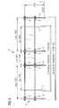
- eine über eine Seitenlänge eines Trafos abgewickelte Darstellung eines Geländers.
- Die
Figur 1 zeigt einen elektrischer Leistungstransformator 1, der in Umspannwerken oft im Freien außerhalb von Betriebsstätten betrieben wird. Der Transformator 1 weist einen Transformator-Gehäusedeckel 11 auf. Auf diesem Trafodeckel 11 ist eine Umwehrung 2 angebracht. Diese Umwehrung 2 ist aus einem elektrischen Nichtleiter in Form eines Kunststoffgeländers hergestellt. Der Trafodeckel 11 weist einen begehbaren Bereich 6 auf, der von einem Instandhaltungspersonal über einen Einstieg 10 von Zeit zu Zeit betreten werden muss, wenn beispielsweise an höher gelegenen Maschinenteilen des Transformators 1, z.B. im Ölbehälter der Füllstand kontrolliert werden muss, oder wenn Reparaturarbeiten oder Wartungsarbeiten auszuführen sind. Das Geländer 2 umschließt lückenlos den äußeren Rand des begehbaren Bereichs 6. Es besteht im Wesentlichen aus Pfosten 3, welche jeweils durch Querleisten, inFigur 1 eine Brustwehr 4 (auch als Handlauf bezeichnet), eine Kniewehr 5 und eine Fußwehr 12, in Umfangsrichtung miteinander verbunden sind. Durch die Umwehrung 2 kann die Absturzgefahr für das Instandhaltungspersonal stark verringert werden. Da alle Bauteile der Umwehrung 2 aus einem elektrisch nicht leitenden Material hergestellt sind, ist eine Demontage des Geländes 2 nach der Ausführung der Instandhaltungsarbeiten nicht erforderlich. Die Umwehrung 2 kann stationär auf dem Trafodeckel 11 angebracht sein. Das Geländer 2 kann sehr leicht an unterschiedliche Baugrößen eines Leistungstransformators angepasst werden. Die Montage des Geländers 2 ist einfach. Das Geländer weist ein geringes Gewicht auf. - Im vorliegenden Ausführungsbeispiel wird für das Geländer 2 der Werkstoff Isophosphatsäure-Polyester verwendet, der mit Strängen von Glasfaser armiert ist. Selbstverständlich sind auch andere Polymerwerkstoffe grundsätzlich geeignet.
- Die Pfosten 3 des Kunststoffgeländers 2 stehen im Wesentlichen senkrecht auf dem Trafodeckel 11. Im Querschnitt sind die Pfosten 3 viereckig ausgebildete Kunststoffrohre der Abmessung 50 mm x 50 mm und weisen eine Wandstärke von 5 mm auf. Sie stecken in Konsolen 13, die am Trafodeckel 11 befestigt sind. Die Pfosten 3 weisen in Umlaufrichtung des Geländers 3 durchgehende Bohrungen auf. Durch diese Bohrungen sind die Querleisten 4, 5, 12 durchgesteckt.
- Die Querleisten 4, 5 und 12 sind glasfaserverstärkte Kunststoffrohre, d.h. handelsübliche GFK-Rohre mit kreisförmigem Querschnitt. Die GFK-Rohre im Bereich des Einstiegs 10, weisen einen äußeren Durchmesser von 30 mm auf. Die umlaufenden GFK-Rohre außerhalb des Einstiegs 10 haben einen äußeren Durchmesser von 40 mm und eine lichte Weite von 32 mm. Dadurch können die GFK-Rohre des Einstiegs in die umlaufenden GFK-Rohre eingeschoben werden.
- Im Folgenden wird an Hand der
Figur 2 und derFigur 3 der Einstig des Instandhaltungspersonals in die Umwährung näher erläutert: In der Detaildarstellung derFigur 2 ist ein Pfosten 3 zu sehen, der den Bereich des Einstiegs 10 (siehe auchFigur 3 ) links begrenzt. An diesen Pfosten 3 ist links und rechts ein Kunststoffrohr 5 bzw. 7 herangeführt. Die Fixierung des Rohrs 5 erfolgt durch eine Kabelverschraubung 8; die Fixierung des Rohrs 7 durch eine Kabelverschraubung 9. Als Kabelverschraubungen 8 bzw. 9 werden sogenannte PG-Verschraubungen verwendet, wie sie sonst üblicherweise zum Fixieren von elektrischen Kabel verwendet werden. Das Öffnen des Einstiegs 10 erfolgt nun so, dass manuell die Kabelverschraubung 9 (und auch die auf der gegenüberliegenden Seite, sieheFigur 3 ) geöffnet wird. Das Kunststoffrohr 7 (Brustwehr, Kniewehr oder Fußwehr) ist nun axial verschiebbar und kann entweder nach links oder nach rechts in die lichte Weite des angrenzenden Kunststoffrohrs soweit hinein geschoben werden, bis der Einstieg für die Instandsetzungsperson frei ist. Sobald sich die Instandsetzungsperson auf dem Trafodeckel 11 befindet, schiebt sie das Rohr 7 wieder in die ursprüngliche Lage zurück. Um sicher zu stellen, dass das Rohr 7 genügend weit zurück geschoben wird, befindet sich auf dem Rohr 7 eine Farbmarkierung. Indem die Kunststoffverschraubung 9 (sowie die auf der gegenüberliegenden Seite) von Hand wieder angezogen wird, wird die Querleiste 7 wieder fixiert. Das Rohr 7 ist auf diese Weise durch Klemmung festgelegt; gleiches gilt für die Querleisten in den übrigen Ebenen, so dass die Umwehrung 2 nach dem Durchstieg wieder lückenlos verschlossen werden kann. Damit ist der Bereich des Einstiegs 10 wieder gesichert. - In der abgewickelten Darstellung der
Figur 3 ist dieser Einstig 10 nochmals zu sehen. Das Geländer 2 weist hier Pfosten 3 auf, die wieder ringsum mit Querleisten 4 und 5 (Brustwehr und Kniewehr) verbunden sind. Je nach Seitenlänge des Transformators (dieFigur 3 zeigt ein Ausführungsbeispiel mit einer Seitenlänge des Trafodeckels von 3700 mm bzw. 5400 mm) ist der Abstand zwischen den Pfosten 3 1400 mm bzw. 1900 mm. An jedem Pfosten 3 ist die durch eine Bohrung hindurch geführte Querleiste 5 bzw. 4 (in derFigur 3 ist eine Ausführung ohne Fußleiste gezeichnet) jeweils durch eine Klemmverschraubung 8 bzw. 9 gesichert. Die Klemmverschraubung 8 bzw. 9 ist mit dem Rohr 5 durch Kleben befestigt. Die Höhe des Geländers 2 über dem begehbaren Bereich 6 ("Oberkante Fußboden" OK) ist im vorliegenden Beispiel 1 m. Die Höhe des Geländers 2 richtet sich dabei selbstverständlich nach der jeweils am Einsatzort des Transformators maßgeblichen nationalen ggf. durch Gesetz vorgegebenen Norm. Der Abstand zwischen der Kniewehr 5 und der Arbeitsfläche 6 ist etwa 0,5 m. Als Querleiste 5 bzw. 6 dient wie bereits erwähnt jeweils ein GFK-Rundrohr. Der Außendurchmesser des GFK-Rohrs ist 40 mm, der Innendurchmesser ist 32 mm. Das GFK-Rohr hat bei einer Länge von 1900 mm und einer quer eingeleiteten Kraft von 300N ein maximales Biegemoment von 142500 Nmm, ein Widerstandsmoment von 3709 mm2; die Biegespannung beträgt 38,4 N/mm2. Dadurch ist das Kunststoffgeländer hinreichend starr und erfüllt viele der durch Bauordnung bzw. Berufsgenossenschaft vorgegebenen Anforderungen. -
- 1
- elektrischen Transformator
- 2
- Absturzs.icherung, Umwehrung, Geländer
- 3
- Pfosten
- 4
- Brustwehr
- 5
- Kniewehr
- 6
- begehbarer Bereich
- 7
- Querleiste im Bereich des Einstiegs 10
- 8
- Kabelverschraubung
- 9
- Kabelverschraubung in 10
- 10
- Einstieg
- 11
- Transformator-Gehäusedeckel
- 12
- Fußwehr
- 13
- Konsole
Claims (8)
- Elektrischer Transformator mit einer Absturzsicherung für Instandhaltungspersonal, das sich im Falle der Durchführung einer Instandhaltungsarbeit auf einem begehbaren Bereich (6) des Transformator-Gehäusedeckels (11) befindet, wobei die Absturzsicherung als Umwehrung (2) ausgebildet ist, wobei die Umwehrung (2) Pfosten (3) aufweist, wobei in Umfangsrichtung gesehen benachbarte Pfosten (3) durch Querleisten (4, 5, 12) verbunden sind, dadurch gekennzeichnet,
dass die Absturzsicherung aus einem elektrisch nicht leitenden polymeren Kunststoff hergestellt ist,
dass jeder Pfosten (3) und jede Querleiste (4, 5, 12) aus einem mit Glasfaser armierten Kunststoff (GFK) hergestellt sind,
dass die Querleisten (4, 5, 12) GFK-Kunststoffrohre mit kreisrundem Querschnitt sind, und
dass jeder Pfosten (3) Bohrungen aufweist, durch welche jeweils ein GFK-Kunststoffrohr (4, 5, 12) hindurch gesteckt ist und beidseits mittels Fixierelementen (8,9) fixiert ist. - Transformator nach Anspruch 1, dadurch gekennzeichnet, dass die Umwehrung (2) am äußeren Rand des begehbaren Bereichs (6) umlaufend ausgebildet ist.
- Transformator nach Anspruch 2, dadurch gekennzeichnet, dass die Pfosten (3) mittels Befestigungsmittel (13) am Transformator-Gehäusedeckel (11) befestigt sind.
- Transformator nach Anspruch 3, dadurch gekennzeichnet, dass jedes Befestigungsmittel (13) jeweils durch eine auf dem Transformator-Gehäusedeckel (11) angebrachte Konsole gebildet ist.
- Transformator nach Anspruch 4, dadurch gekennzeichnet, dass die Anordnung der Pfosten (3) und der Querleisten (4, 5, 12) so gewählt ist, dass sie ein Geländer bilden, welches eine Brustwehr (4), eine Kniewehr (4) und eine Fußwehr (12) aufweist.
- Transformator nach Anspruch 5, dadurch gekennzeichnet, dass in einem Einstiegsbereich (10) der Umwehrung (2) zur Verbindung benachbart gegenüberliegender Pfosten (3) GFK-Kunststoffrohre (7) verwendet werden, welche jeweils in die lichte Weite zugeordneter GFK-Kunststoffrohre (4, 5, 12) der umlaufenden Umwehrung (2) nach Art eines Teleskops einschiebbar sind.
- Transformator nach Anspruch 6, dadurch gekennzeichnet, dass jedes Fixierelement (8,9) durch eine Kabelverschraubung aus Kunststoff gebildet ist.
- Elektrischer Transformator mit einer Absturzsicherung für Instandhaltungspersonal, das sich im Falle der Durchführung einer Instandhaltungsarbeit auf einem begehbaren Bereich (6) des Transformator-Gehäusedeckels (11) befindet, wobei die Absturzsicherung als Umwehrung (2) ausgebildet ist, wobei die Umwehrung (2) Pfosten (3) aufweist, wobei in Umfangsrichtung gesehen benachbarte Pfosten (3) durch Querleisten (4, 5, 12) verbunden sind, dadurch gekennzeichnet,
dass die Absturzsicherung aus einem elektrisch nicht leitenden polymeren Kunststoff hergestellt ist,
dass jeder Pfosten (3) und jede Querleitste (4, 5, 12) aus einem mit Glasfaser armierten Kunststoff (GFK) hergestellt sind,
dass die Querleisten(4, 5, 12) GFK-Kunststoffrohre mit kreisrundem Querschnitt sind, und in einem Einstiegsbereich (10) der Umwehrung (2) zur Verbindung benachbart gegenüberliegender Pfosten (3) GFK-Kunststoffrohre verwendet werden, welche jeweils in die lichte Weite zugeordneter GFK-Kunststoffrohre der umlaufenden Umwehrung nach Art eines Teleskops einschiebbar sind.
Applications Claiming Priority (2)
| Application Number | Priority Date | Filing Date | Title |
|---|---|---|---|
| DE102007025689A DE102007025689A1 (de) | 2007-06-01 | 2007-06-01 | Elektrischer Transformator mit einer Absturzsicherung |
| PCT/EP2008/052552 WO2008145419A1 (de) | 2007-06-01 | 2008-03-03 | Elektrischer transformator mit einer absturzsicherung |
Publications (2)
| Publication Number | Publication Date |
|---|---|
| EP2153449A1 EP2153449A1 (de) | 2010-02-17 |
| EP2153449B1 true EP2153449B1 (de) | 2014-02-26 |
Family
ID=39485122
Family Applications (1)
| Application Number | Title | Priority Date | Filing Date |
|---|---|---|---|
| EP08717315.9A Not-in-force EP2153449B1 (de) | 2007-06-01 | 2008-03-03 | Elektrischer transformator mit einer absturzsicherung |
Country Status (3)
| Country | Link |
|---|---|
| EP (1) | EP2153449B1 (de) |
| DE (1) | DE102007025689A1 (de) |
| WO (1) | WO2008145419A1 (de) |
Families Citing this family (2)
| Publication number | Priority date | Publication date | Assignee | Title |
|---|---|---|---|---|
| US10883275B2 (en) * | 2018-06-22 | 2021-01-05 | Cv International, Inc. | Transformer-integrated guardrail apparatus and kit |
| US20240350836A1 (en) * | 2023-04-24 | 2024-10-24 | Cv International, Inc. | Safety systems and rescue systems for elevated worksites |
Family Cites Families (7)
| Publication number | Priority date | Publication date | Assignee | Title |
|---|---|---|---|---|
| DE2422356A1 (de) * | 1974-05-06 | 1975-11-20 | Friedrich Wilhelm Latteyer | Unfallverhuetung |
| US4053140A (en) * | 1976-04-29 | 1977-10-11 | Clemens Donald L | Fiber reinforced plastic handrail system |
| US6039150A (en) * | 1995-05-03 | 2000-03-21 | Palmer; Theodore R. | Building guard rail scaffold assembly |
| US5718305A (en) * | 1996-11-01 | 1998-02-17 | Palmer; Theodore Richard | Safety harness attachment post assembly |
| DE10297757T5 (de) * | 2002-06-20 | 2005-06-30 | Otis Elevator Co., Farmington | Sicherheitsaufbaubalustrade für eine Kabine eines Maschinenraum-losen Aufzugs |
| CA2424466C (en) * | 2003-04-04 | 2010-01-26 | Unique Concepts Ltd. | Fall restraint anchoring post |
| DE20306255U1 (de) * | 2003-04-17 | 2003-07-10 | Spitzke AG, 14979 Großbeeren | Arbeitsbühne |
-
2007
- 2007-06-01 DE DE102007025689A patent/DE102007025689A1/de not_active Withdrawn
-
2008
- 2008-03-03 WO PCT/EP2008/052552 patent/WO2008145419A1/de not_active Ceased
- 2008-03-03 EP EP08717315.9A patent/EP2153449B1/de not_active Not-in-force
Also Published As
| Publication number | Publication date |
|---|---|
| DE102007025689A1 (de) | 2008-12-11 |
| EP2153449A1 (de) | 2010-02-17 |
| WO2008145419A1 (de) | 2008-12-04 |
Similar Documents
| Publication | Publication Date | Title |
|---|---|---|
| DE102013217088A1 (de) | Verfahren zur Montage von Turmeinbauten | |
| EP2820294B1 (de) | Windenergieanlage mit brandschutzmodul für transformator im turm | |
| EP2153449B1 (de) | Elektrischer transformator mit einer absturzsicherung | |
| DE102009048149A1 (de) | System zum Erstellen eines Flucht-, Rettungs- oder Dienstwegs in Gleisanlagen | |
| EP4047137A1 (de) | Fundament für eine säule mit innen geführten kabeln, beispielsweise für eine elektrofahrzeug-ladesäule oder einen parkscheinautomaten | |
| DE202010009722U1 (de) | Kabel- und Leitungsführung | |
| DE202011101596U1 (de) | Gleissicherungseinrichtung (Feste Absperrung) | |
| DE60318350T2 (de) | Schutzgeländervorrichtung | |
| EP3938715B1 (de) | Heizmatte zur verwendung in einem fussbodenaufbau, fussbodenaufbau und verfahren zu dessen herstellung | |
| DE202020000714U1 (de) | Transversal verstellbare, an Gleisen und Weichen montierbare, von außerhalb des Gefahrenbereiches bedienbare feste Absperrung als Schutzvorrichtung am Oberbau gegen das unbeabsichtigte Betreten des Gleises durch Arbeitskräfte bei Arbeiten im Bereich von Bahnanlagen | |
| DE102020001133A1 (de) | Gleissicherungseinrichtung | |
| DE19549191C1 (de) | Freileitungsmast aus Stahlprofil-Gitterstäben und Verfahren zur Einrichtung von hochvorgespannten geschraubten Verbindungen an einem Freileitungsmast | |
| DE202010000420U1 (de) | Isolierende Vogelschutzabdeckung | |
| DE202018006350U1 (de) | Vorrichtung zum abgedichteten Durchführen von Kabeln und/oder Leitungen durch eine Bodenplatte in ein Gebäude | |
| AT527805B1 (de) | Befestigung für ein Kabelführungsrohr | |
| EP3477019A1 (de) | In der dachkonstruktion wärmebrückenfrei fixierter pfosten für absturzsicherungen oder absturzsicherungssysteme | |
| DE202019001499U1 (de) | Abstandshalter für Gerüstaufbauten | |
| DE2914078C2 (de) | Schutzanordnung für während des Seilzugs elektrischer Freileitungen zu kreuzende Anlagen | |
| DE3036629A1 (de) | Haltevorrichtung fuer luftverlegte, leichte fernmeldekabel oder optische kabel | |
| DE20206268U1 (de) | Verbindungssystem für Wandungsteile | |
| AT508666B1 (de) | Lichtkuppel | |
| DE202024001964U1 (de) | Absturzsicherungsgeländer für elektrische Transformatoren | |
| DE8808533U1 (de) | Zaungitter mit Sicherungsvorrichtung | |
| DE202023107164U1 (de) | Zaun mit Vertikal-Spannvorrichtung | |
| EP1333208B1 (de) | Vorrichtung zum Aufhängen einer Einrichtung an einer Raumdecke |
Legal Events
| Date | Code | Title | Description |
|---|---|---|---|
| PUAI | Public reference made under article 153(3) epc to a published international application that has entered the european phase |
Free format text: ORIGINAL CODE: 0009012 |
|
| 17P | Request for examination filed |
Effective date: 20090922 |
|
| AK | Designated contracting states |
Kind code of ref document: A1 Designated state(s): AT BE BG CH CY CZ DE DK EE ES FI FR GB GR HR HU IE IS IT LI LT LU LV MC MT NL NO PL PT RO SE SI SK TR |
|
| AX | Request for extension of the european patent |
Extension state: AL BA MK RS |
|
| DAX | Request for extension of the european patent (deleted) | ||
| RAP1 | Party data changed (applicant data changed or rights of an application transferred) |
Owner name: SIEMENS AG OESTERREICH |
|
| 17Q | First examination report despatched |
Effective date: 20130130 |
|
| GRAP | Despatch of communication of intention to grant a patent |
Free format text: ORIGINAL CODE: EPIDOSNIGR1 |
|
| INTG | Intention to grant announced |
Effective date: 20130913 |
|
| GRAS | Grant fee paid |
Free format text: ORIGINAL CODE: EPIDOSNIGR3 |
|
| GRAA | (expected) grant |
Free format text: ORIGINAL CODE: 0009210 |
|
| AK | Designated contracting states |
Kind code of ref document: B1 Designated state(s): AT BE BG CH CY CZ DE DK EE ES FI FR GB GR HR HU IE IS IT LI LT LU LV MC MT NL NO PL PT RO SE SI SK TR |
|
| REG | Reference to a national code |
Ref country code: GB Ref legal event code: FG4D Free format text: NOT ENGLISH |
|
| REG | Reference to a national code |
Ref country code: CH Ref legal event code: EP |
|
| REG | Reference to a national code |
Ref country code: AT Ref legal event code: REF Ref document number: 654007 Country of ref document: AT Kind code of ref document: T Effective date: 20140315 |
|
| REG | Reference to a national code |
Ref country code: IE Ref legal event code: FG4D Free format text: LANGUAGE OF EP DOCUMENT: GERMAN |
|
| REG | Reference to a national code |
Ref country code: DE Ref legal event code: R096 Ref document number: 502008011348 Country of ref document: DE Effective date: 20140410 |
|
| PGFP | Annual fee paid to national office [announced via postgrant information from national office to epo] |
Ref country code: NL Payment date: 20140303 Year of fee payment: 7 |
|
| REG | Reference to a national code |
Ref country code: NL Ref legal event code: T3 |
|
| REG | Reference to a national code |
Ref country code: LT Ref legal event code: MG4D |
|
| PG25 | Lapsed in a contracting state [announced via postgrant information from national office to epo] |
Ref country code: IS Free format text: LAPSE BECAUSE OF FAILURE TO SUBMIT A TRANSLATION OF THE DESCRIPTION OR TO PAY THE FEE WITHIN THE PRESCRIBED TIME-LIMIT Effective date: 20140626 Ref country code: LT Free format text: LAPSE BECAUSE OF FAILURE TO SUBMIT A TRANSLATION OF THE DESCRIPTION OR TO PAY THE FEE WITHIN THE PRESCRIBED TIME-LIMIT Effective date: 20140226 Ref country code: NO Free format text: LAPSE BECAUSE OF FAILURE TO SUBMIT A TRANSLATION OF THE DESCRIPTION OR TO PAY THE FEE WITHIN THE PRESCRIBED TIME-LIMIT Effective date: 20140526 |
|
| PG25 | Lapsed in a contracting state [announced via postgrant information from national office to epo] |
Ref country code: PT Free format text: LAPSE BECAUSE OF FAILURE TO SUBMIT A TRANSLATION OF THE DESCRIPTION OR TO PAY THE FEE WITHIN THE PRESCRIBED TIME-LIMIT Effective date: 20140626 Ref country code: SE Free format text: LAPSE BECAUSE OF FAILURE TO SUBMIT A TRANSLATION OF THE DESCRIPTION OR TO PAY THE FEE WITHIN THE PRESCRIBED TIME-LIMIT Effective date: 20140226 Ref country code: FI Free format text: LAPSE BECAUSE OF FAILURE TO SUBMIT A TRANSLATION OF THE DESCRIPTION OR TO PAY THE FEE WITHIN THE PRESCRIBED TIME-LIMIT Effective date: 20140226 Ref country code: CY Free format text: LAPSE BECAUSE OF FAILURE TO SUBMIT A TRANSLATION OF THE DESCRIPTION OR TO PAY THE FEE WITHIN THE PRESCRIBED TIME-LIMIT Effective date: 20140226 |
|
| PGFP | Annual fee paid to national office [announced via postgrant information from national office to epo] |
Ref country code: DE Payment date: 20140519 Year of fee payment: 7 |
|
| PG25 | Lapsed in a contracting state [announced via postgrant information from national office to epo] |
Ref country code: HR Free format text: LAPSE BECAUSE OF FAILURE TO SUBMIT A TRANSLATION OF THE DESCRIPTION OR TO PAY THE FEE WITHIN THE PRESCRIBED TIME-LIMIT Effective date: 20140226 Ref country code: LV Free format text: LAPSE BECAUSE OF FAILURE TO SUBMIT A TRANSLATION OF THE DESCRIPTION OR TO PAY THE FEE WITHIN THE PRESCRIBED TIME-LIMIT Effective date: 20140226 |
|
| PG25 | Lapsed in a contracting state [announced via postgrant information from national office to epo] |
Ref country code: CZ Free format text: LAPSE BECAUSE OF FAILURE TO SUBMIT A TRANSLATION OF THE DESCRIPTION OR TO PAY THE FEE WITHIN THE PRESCRIBED TIME-LIMIT Effective date: 20140226 Ref country code: EE Free format text: LAPSE BECAUSE OF FAILURE TO SUBMIT A TRANSLATION OF THE DESCRIPTION OR TO PAY THE FEE WITHIN THE PRESCRIBED TIME-LIMIT Effective date: 20140226 Ref country code: DK Free format text: LAPSE BECAUSE OF FAILURE TO SUBMIT A TRANSLATION OF THE DESCRIPTION OR TO PAY THE FEE WITHIN THE PRESCRIBED TIME-LIMIT Effective date: 20140226 Ref country code: RO Free format text: LAPSE BECAUSE OF FAILURE TO SUBMIT A TRANSLATION OF THE DESCRIPTION OR TO PAY THE FEE WITHIN THE PRESCRIBED TIME-LIMIT Effective date: 20140226 |
|
| REG | Reference to a national code |
Ref country code: CH Ref legal event code: PL |
|
| REG | Reference to a national code |
Ref country code: DE Ref legal event code: R097 Ref document number: 502008011348 Country of ref document: DE |
|
| PG25 | Lapsed in a contracting state [announced via postgrant information from national office to epo] |
Ref country code: ES Free format text: LAPSE BECAUSE OF FAILURE TO SUBMIT A TRANSLATION OF THE DESCRIPTION OR TO PAY THE FEE WITHIN THE PRESCRIBED TIME-LIMIT Effective date: 20140226 Ref country code: MC Free format text: LAPSE BECAUSE OF FAILURE TO SUBMIT A TRANSLATION OF THE DESCRIPTION OR TO PAY THE FEE WITHIN THE PRESCRIBED TIME-LIMIT Effective date: 20140226 Ref country code: PL Free format text: LAPSE BECAUSE OF FAILURE TO SUBMIT A TRANSLATION OF THE DESCRIPTION OR TO PAY THE FEE WITHIN THE PRESCRIBED TIME-LIMIT Effective date: 20140226 Ref country code: SK Free format text: LAPSE BECAUSE OF FAILURE TO SUBMIT A TRANSLATION OF THE DESCRIPTION OR TO PAY THE FEE WITHIN THE PRESCRIBED TIME-LIMIT Effective date: 20140226 |
|
| REG | Reference to a national code |
Ref country code: IE Ref legal event code: MM4A |
|
| PLBE | No opposition filed within time limit |
Free format text: ORIGINAL CODE: 0009261 |
|
| STAA | Information on the status of an ep patent application or granted ep patent |
Free format text: STATUS: NO OPPOSITION FILED WITHIN TIME LIMIT |
|
| GBPC | Gb: european patent ceased through non-payment of renewal fee |
Effective date: 20140526 |
|
| PG25 | Lapsed in a contracting state [announced via postgrant information from national office to epo] |
Ref country code: IE Free format text: LAPSE BECAUSE OF NON-PAYMENT OF DUE FEES Effective date: 20140303 Ref country code: CH Free format text: LAPSE BECAUSE OF NON-PAYMENT OF DUE FEES Effective date: 20140331 Ref country code: LI Free format text: LAPSE BECAUSE OF NON-PAYMENT OF DUE FEES Effective date: 20140331 |
|
| 26N | No opposition filed |
Effective date: 20141127 |
|
| REG | Reference to a national code |
Ref country code: DE Ref legal event code: R097 Ref document number: 502008011348 Country of ref document: DE Effective date: 20141127 |
|
| REG | Reference to a national code |
Ref country code: FR Ref legal event code: ST Effective date: 20150210 |
|
| PG25 | Lapsed in a contracting state [announced via postgrant information from national office to epo] |
Ref country code: IT Free format text: LAPSE BECAUSE OF FAILURE TO SUBMIT A TRANSLATION OF THE DESCRIPTION OR TO PAY THE FEE WITHIN THE PRESCRIBED TIME-LIMIT Effective date: 20140226 |
|
| REG | Reference to a national code |
Ref country code: AT Ref legal event code: MM01 Ref document number: 654007 Country of ref document: AT Kind code of ref document: T Effective date: 20140303 |
|
| PG25 | Lapsed in a contracting state [announced via postgrant information from national office to epo] |
Ref country code: FR Free format text: LAPSE BECAUSE OF NON-PAYMENT OF DUE FEES Effective date: 20140428 Ref country code: GB Free format text: LAPSE BECAUSE OF NON-PAYMENT OF DUE FEES Effective date: 20140526 Ref country code: SI Free format text: LAPSE BECAUSE OF FAILURE TO SUBMIT A TRANSLATION OF THE DESCRIPTION OR TO PAY THE FEE WITHIN THE PRESCRIBED TIME-LIMIT Effective date: 20140226 |
|
| PG25 | Lapsed in a contracting state [announced via postgrant information from national office to epo] |
Ref country code: AT Free format text: LAPSE BECAUSE OF NON-PAYMENT OF DUE FEES Effective date: 20140303 |
|
| REG | Reference to a national code |
Ref country code: DE Ref legal event code: R119 Ref document number: 502008011348 Country of ref document: DE |
|
| REG | Reference to a national code |
Ref country code: NL Ref legal event code: MM Effective date: 20150401 |
|
| PG25 | Lapsed in a contracting state [announced via postgrant information from national office to epo] |
Ref country code: DE Free format text: LAPSE BECAUSE OF NON-PAYMENT OF DUE FEES Effective date: 20151001 |
|
| PG25 | Lapsed in a contracting state [announced via postgrant information from national office to epo] |
Ref country code: MT Free format text: LAPSE BECAUSE OF FAILURE TO SUBMIT A TRANSLATION OF THE DESCRIPTION OR TO PAY THE FEE WITHIN THE PRESCRIBED TIME-LIMIT Effective date: 20140226 |
|
| PG25 | Lapsed in a contracting state [announced via postgrant information from national office to epo] |
Ref country code: BG Free format text: LAPSE BECAUSE OF FAILURE TO SUBMIT A TRANSLATION OF THE DESCRIPTION OR TO PAY THE FEE WITHIN THE PRESCRIBED TIME-LIMIT Effective date: 20140226 |
|
| PG25 | Lapsed in a contracting state [announced via postgrant information from national office to epo] |
Ref country code: GR Free format text: LAPSE BECAUSE OF FAILURE TO SUBMIT A TRANSLATION OF THE DESCRIPTION OR TO PAY THE FEE WITHIN THE PRESCRIBED TIME-LIMIT Effective date: 20140527 |
|
| PG25 | Lapsed in a contracting state [announced via postgrant information from national office to epo] |
Ref country code: HU Free format text: LAPSE BECAUSE OF FAILURE TO SUBMIT A TRANSLATION OF THE DESCRIPTION OR TO PAY THE FEE WITHIN THE PRESCRIBED TIME-LIMIT; INVALID AB INITIO Effective date: 20080303 Ref country code: BE Free format text: LAPSE BECAUSE OF FAILURE TO SUBMIT A TRANSLATION OF THE DESCRIPTION OR TO PAY THE FEE WITHIN THE PRESCRIBED TIME-LIMIT Effective date: 20140331 Ref country code: LU Free format text: LAPSE BECAUSE OF NON-PAYMENT OF DUE FEES Effective date: 20140303 Ref country code: TR Free format text: LAPSE BECAUSE OF FAILURE TO SUBMIT A TRANSLATION OF THE DESCRIPTION OR TO PAY THE FEE WITHIN THE PRESCRIBED TIME-LIMIT Effective date: 20140226 |
|
| PG25 | Lapsed in a contracting state [announced via postgrant information from national office to epo] |
Ref country code: NL Free format text: LAPSE BECAUSE OF NON-PAYMENT OF DUE FEES Effective date: 20150401 |