EP2153713A2 - Pflanzenstecktopf - Google Patents
Pflanzenstecktopf Download PDFInfo
- Publication number
- EP2153713A2 EP2153713A2 EP09167610A EP09167610A EP2153713A2 EP 2153713 A2 EP2153713 A2 EP 2153713A2 EP 09167610 A EP09167610 A EP 09167610A EP 09167610 A EP09167610 A EP 09167610A EP 2153713 A2 EP2153713 A2 EP 2153713A2
- Authority
- EP
- European Patent Office
- Prior art keywords
- receptacle
- structural
- plant
- plant receptacle
- web
- Prior art date
- Legal status (The legal status is an assumption and is not a legal conclusion. Google has not performed a legal analysis and makes no representation as to the accuracy of the status listed.)
- Withdrawn
Links
Images


Classifications
-
- A—HUMAN NECESSITIES
- A01—AGRICULTURE; FORESTRY; ANIMAL HUSBANDRY; HUNTING; TRAPPING; FISHING
- A01G—HORTICULTURE; CULTIVATION OF VEGETABLES, FLOWERS, RICE, FRUIT, VINES, HOPS OR SEAWEED; FORESTRY; WATERING
- A01G9/00—Cultivation in receptacles, forcing-frames or greenhouses; Edging for beds, lawn or the like
- A01G9/02—Receptacles, e.g. flower-pots or boxes; Glasses for cultivating flowers
- A01G9/026—Foldable pots
-
- A—HUMAN NECESSITIES
- A01—AGRICULTURE; FORESTRY; ANIMAL HUSBANDRY; HUNTING; TRAPPING; FISHING
- A01G—HORTICULTURE; CULTIVATION OF VEGETABLES, FLOWERS, RICE, FRUIT, VINES, HOPS OR SEAWEED; FORESTRY; WATERING
- A01G9/00—Cultivation in receptacles, forcing-frames or greenhouses; Edging for beds, lawn or the like
- A01G9/02—Receptacles, e.g. flower-pots or boxes; Glasses for cultivating flowers
- A01G9/029—Receptacles for seedlings
- A01G9/0291—Planting receptacles specially adapted for remaining in the soil after planting
Definitions
- the present invention concerns a plant receptacle with at least one opening and a method for forming at least one structural area on such a plant receptacle, where the plant receptacle is preferably formed of a fibrous web or sheet material.
- the invention furthermore concerns an apparatus for manufacturing such a plant receptacle.
- pots In connection with transplanting plants that are sprouted, set or transplanted in e.g. a greenhouse, it is known to place the plants in small pots. These pots can be made of plastic, alternatively of paperboard and sphagnum.
- pots of fibre material such as paperboard, sphagnum, or combinations thereof
- pots can be made that are decomposable in nature, and which therefore in principle can be placed in the earth with the plant in it.
- This decomposition is, however, so slow that the roots of the plant cannot grow and spread quickly enough.
- pots made of sphagnum or cardboard are relatively expensive to make, both with regard to the material price and the manufacturing processes.
- a plant can be set to sprouting, or be transplanted in a plant receptacle in e.g. a greenhouse for a period prior to final transplanting in the open, and where the plant receptacle is decomposed or dissolved rapidly after transplanting, thus not limiting the roots of the plants, as well as the receptacle being made by a rational process from relatively cheap materials, hereby reducing the total price per receptacle.
- receptacles according to the invention do not entail any contamination or inexpedient influences, but to the contrary provide a lot of advantages to the sprouting plants.
- the present invention concerns a plant receptacle with at least one opening, and a method for forming a structural area on such a plant receptacle, where the plant receptacle preferably is formed of a fibrous web or sheet material.
- the invention furthermore concerns an apparatus for manufacturing such a plant receptacle.
- the web or sheet material is preferably a cotton fibre material, e.g. vlies, with a first structural strength, where the plant receptacle has at least one structural area with a different and greater strength, where this different structural area is formed by wetting, compressing and subsequent drying of a part of the web or sheet material.
- the material may be produced from cotton only, or, in another preferred variant, be a mixture of preferably cotton and one or more grass species. Among the preferred grasses, bamboo and palm materials are particularly used. The addition of grass to the cotton material in the form of vlies, i.e.
- the decomposition time may thus be predetermined with regard to the kind of plant to which the plant receptacle is to be used and to the soil conditions and climatic conditions present at the particular cultivation location.
- Wetting can be performed with water, alternatively with a glue or a binder which is non-toxic and decomposable in the nature.
- the soaked fibres are very soft, and by compressing these structural areas with greater density or at least with increased material thickness can be achieved in comparison with the original web or sheet material.
- increased strength does not occur before the fibre material has dried again, and thereby increased stiffness and strength are achieved.
- it is a process in which fibres in wetted fibre material come into mutual contact by compression and are thereby entangled. The fibres are retained in this position until a part of the supplied liquid is evaporated, e.g. by heat action, and thereafter the treated local area appears with a different and greater strength.
- a variant of the plant receptacle according to the invention is where the plant receptacle at least along one edge is provided with one or more structural areas with a different strength, where these areas constitute joints of web or sheet material, e.g. a punctiform joint.
- joints there may e.g. be formed a bag which can be used for sprouting, setting or transplanting therein.
- the bag is e.g. filled with sphagnum or potting compost, and a potato is set in it.
- the bag may then be placed in a suitable tray or box and put in a warm and suitable place until the sprouting is well under way, and may subsequently be transplanted in the garden where the bag with the sprouting potato is set directly in the earth.
- the bag which is made of a decomposable fibrous web or sheet material, will disappear in a relatively short time, and when the transplanted plants are harvested, the bag will be decomposed. Therefore, it is not necessary to collect remains of these plant receptacles in the earth in the garden before the next transplanting.
- the plant receptacle is provided with one or more structural areas with a different strength, where these areas constitute a reinforcing collar or rib of compressed web or sheet material.
- This may e.g. be an upper edge of a pot as known from the traditional pots of plastic or cardboard. It may also be that longitudinal or transverse reinforcing ribs are made on a plant receptacle.
- a plant receptacle can, for example, be made tubular where the side is closed with punctiform joints, where the bottom is constituted by an area with increased strength and where there are an upper reinforcing collar on the receptacle, rings extending around the receptacle as well as longitudinal reinforcing ribs on the side.
- Such a plant receptacle has the advantage that it is very stable in shape which can be advantageous during the work with sowing, setting or planting. Obviously, many other combinations may be envisaged.
- Such plant receptacles may advantageously be made of a web or sheet material of a water-soluble vlies, e.g. of cotton fibres. It is thus a natural material which is relatively easily decomposed by the moisture in the earth without negative consequences, and which at the same time is cheap and has the desired properties.
- Such vlies materials can be made with different thicknesses and densities, and these may be selected according to need and according to the conditions for which the plant receptacles are intended.
- the plant receptacle is provided with an opening at the top, and along a bottom edge arranged with a structural area constituting a bottom, and where one or more structural areas are provided from the bottom edge to the top edge.
- the receptacle is conical and at least partially filled with soil, sphagnum or other growth medium, the conical shape of the receptacle will retain the plant such that the bottom is not necessary.
- a second plant receptacle is arranged within a first plant receptacle, the second receptacle having dimensions which are larger than those of the first receptacle, possibly except the distance from the bottom edge to the top edge, and where excess material from the second receptacle is folded and treated such that structural zones are formed in parallel with the structural zones of the first receptacle; and where the folded structural zones may optionally be superposed and integrated with the structural zones of the first receptacle; and where the top edge with at least double material layer thickness may optionally be bent and treated such that structural area is also formed here.
- a plant receptacle which has required strength for hanging, i.e. not needing to stand on a base.
- the plant receptacles with seeds, sprouts, cuttings and other are suspended such that only the lowermost part of the receptacle is in contact with water.
- suspending the receptacles these may via conveyor chains or other be automatically transported through the greenhouses without manual treatment, entailing a great saving.
- a plant receptacle according to the invention may advantageously be produced by an apparatus that forms at least one structural area on a plant receptacle, where the plant receptacle is formed of a fibrous material, preferably a web or sheet material.
- Such an apparatus may include at least one pressing tool with two parts, namely a first part - preferably with a cutout - and a second part - preferably with a projection corresponding to the first part - between which the fibrous material is placed and pressed. It may thus be a depression in which the fibre material is pressed down by a mandrel.
- the fibre material is contracted, and the mandrel ensures that the fibres in the depressions will cohere, i.e. become entangled such that a relatively strong joint between the two layers in this zone arises.
- the fibre material is wetted, which may be effected in the said apparatus as the pressing tool may be with at least one integrated channel for supplying liquid to the fibrous material.
- the supplied liquid may be heated water which is either supplied from an external water heater or which alternatively is heated on its way through the integrated channel.
- An apparatus according to the invention may furthermore include a tool with integrated heating element.
- This heating element has the purpose of evaporating the supplied liquid to such a degree that the fibre material again attains sufficient strength in order for the plant receptacle to be handled in the subsequent process.
- This evaporation of liquid may also occur under use of a heat blower arranged in connection with the tool or in immediate vicinity thereof.
- the apparatus may be adapted such that the second part of the tool is provided with projections as well as a spring-loaded ejector.
- the projection and the fibrous material can be separated without tearing the wet and thereby rather weak fibre material.
- the ejector moreover has the function that it retains the fibrous layer or layers in position immediately before compressing as the ejector will get in contact with the fibre material before the pressing itself.
- the pressing tool is made up of two pressing wheels arranged on separate shafts, where the wheels are provided along the periphery with a number of grooves such that the structural area is formed by the material passes between the two wheels that are pressed together, whereby the grooves exert an appropriate pressure such that the fibres in the two material layers are entangled.
- the grooves which may be freely oriented relative to the periphery of the wheel will, when two material layers pass through the opposed wheels, compress the material arranged between the wheels.
- the fibres are hereby entangled in the areas that are subjected to the pressure of the grooves. A rational and rapid production may be provided by using more wheel sets.
- the plant receptacle In a preferred embodiment of the plant receptacle, it has shape as a frustum of a cone with compressed bottom and largely circular or oval upper opening. Along two edges in the frustum of a cone there are structural areas connecting two layers of material, whereby the receptacle is provided its shape and structure. The extension of the bottom will typically be substantially less than that of the opening. In use is hereby achieved that roots penetrating through the material are not entangled with roots from an adjacent plant as the upper edges keep a certain distance between the plants.
- the above described principle of forming structural zones is thus based on choosing a fibre material as e.g. cotton, which by wetting/moisturising allows the individual fibres to be manipulated.
- the manipulation occurs by two or more layers of material being pressed together, whereby fibres in different layers are entangled.
- a plant receptacle 1 which is made as a bag of a web or sheet material 2 of a fibrous material, e.g. vlies of cotton.
- the plant receptacle 1 is made by folding the fibre material and along a bottom edge 3 and a side edge 4 joints 5 are made by compressing wetted fibres in minor, local areas. In principle, this is a series of punctiform joints 5.
- reinforcing longitudinal ribs 6 and transverse ribs 7 are made.
- the joint along the edges 3 and 4 could also be made as elongated compressions corresponding to the ribs 6 and 7.
- Fig. 2 is further seen a variant of a plant receptacle 1 which is shown here with triangular shape.
- joints 5 are only made along one edge 7.
- longitudinal reinforcing ribs 6 On this variant, there are also produced longitudinal reinforcing ribs 6.
- a stiffening and shaping edge 10 where the fibre material is compressed, thereby appearing with a different and higher strength than the initial strength.
- Fig. 3 is seen a variant of a plant receptacle 1 which is shown here with the same shape as a classical pot.
- a compression of the fibre material which thus appears as a collar with increased strength due to higher density/thickness, but also because the collar is made with an angular and thereby reinforcing design.
- Such a pot may furthermore be with ribs as shown in Figs. 1 and 2 , and may possibly be with an area at the bottom 11 which is also reinforced.
- Fig. 4 appears an example of an apparatus 12 for performing a compression of the fibre material 13.
- the shown apparatus 12 is depicted very schematically and may of course have innumerable other designs.
- a tool part 14 with a depression 15 into which a corresponding projection 16 on the upper tool part 17 fits.
- the tool 14, 17 is furthermore provided with an ejector 18, 19 that consists of a spring 18 and a thrust plate 19. This thrust plate 19 is arranged such that it bears on the fibre material 13 before the projection 16 comes into contact with it.
- the springs 18 are also pressed together and the fibre material is fixed.
- the spring force is adjusted such that the desired pressure is attained, and therefore it may very well be so that the fibre material can be drawn with down into the depression 15 by the projection 16, irrespective of the ejector 18, 19 pressing on it. Also, the ejector 18, 19 ensures that the fibre material 13 during opening of the apparatus 12 is not caught on the projection 16 when the latter is retracted.
- the shown variant of the apparatus 12 may be intended for punctiform joints 5 as shown in Figs. 1 and 2 , or for elongated ribs 6 and 7, or for edges 8, 10.
- the tools may thus be elongated, punctiform or even designed as two rolling tools, where the joining is effected continuously along e.g. an edge 3, 4, 7.
- the apparatus 12 may also be with not shown channels for supplying water or glue, and furthermore there may be integrated one or more not shown heating elements in one or more of the tool parts 14, 17.
- Fig. 5 are illustrated schematically different phases in a production method. Two webs of material 20, 20' are laid upon each other and continued in the apparatus (not shown). By means of a number of pressing wheels 30, as illustrated in fig. 7 , the structural zones 21 are formed.
- the shown example in Fig. 5 is thus made by means of four sets of wheel pairs: Two wheel pair sets for forming opposing structural bottom zones 22, 23 and two wheel pair sets for forming the longitudinal sides 24, 25.
- the sides 24, 25 are angled so that the bottom 22, 23 of the receptacles has less extension than the top (opening) 26.
- one pair of wheels can be used, an upper and a lower wheel, respectively.
- the surface of the wheels are provided with grooves corresponding to the indicated structural zones such that structural zones as illustrated are continuously formed by rotating the wheels with layers of material there between.
- Fig. 6 is illustrated how the individual receptacles 27 are cut free by cutting in the structural zones such that each receptacle 27 is limited by half a structural zone 24, 25, 24', 25'.
- a pressing wheel 30 that may form part of the above mentioned wheel pairs is shown schematically.
- the periphery 28 of the wheel 30 is provided with a number of grooves 29.
- material located between the wheels will be compressed opposite the wheels 29, whereby the structural zones are formed.
- the grooves 29 are shown largely in parallel with the shaft 31, but the grooves 29 may be oriented at any angle relative to the shaft.
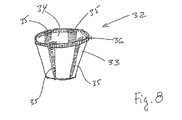
- Fig. 8 is illustrated a yet a design variant of a receptacle according to the invention.
- the receptacle 32 is constructed by putting two different sizes of receptacles 33, 34 within each other.
- the receptacle 34 is thus larger than the outer receptacle 33.
- excess material appears. This material is bent such that at some points, four shown here, overlap zones 35 are formed. These overlap zones 35 are pressed together whereby structural zones are formed.
- the upper edge may be bent whereby an annular structural zone 36 appears.
- the receptacle is here illustrated without a bottom, but it may of course be provided with a bottom.
- the receptacle can be made in that the internal receptacle is placed inside the outer receptacle by means of a conical tool, and that on the cone or on an outer mould in which the outer receptacle is arranged there are provided pressing zones, i.e. zones corresponding to the overlaps 35, where a great pressure is exerted between the material layers such that the structural zones 35, 36 are formed.
Landscapes
- Life Sciences & Earth Sciences (AREA)
- Environmental Sciences (AREA)
- Cultivation Receptacles Or Flower-Pots, Or Pots For Seedlings (AREA)
- Nonwoven Fabrics (AREA)
Applications Claiming Priority (1)
| Application Number | Priority Date | Filing Date | Title |
|---|---|---|---|
| DKPA200801108 | 2008-08-11 |
Publications (2)
| Publication Number | Publication Date |
|---|---|
| EP2153713A2 true EP2153713A2 (de) | 2010-02-17 |
| EP2153713A3 EP2153713A3 (de) | 2011-03-30 |
Family
ID=41335231
Family Applications (1)
| Application Number | Title | Priority Date | Filing Date |
|---|---|---|---|
| EP09167610A Withdrawn EP2153713A3 (de) | 2008-08-11 | 2009-08-11 | Pflanzenstecktopf |
Country Status (4)
| Country | Link |
|---|---|
| US (1) | US20100031567A1 (de) |
| EP (1) | EP2153713A3 (de) |
| BR (1) | BRPI0902708A2 (de) |
| CA (1) | CA2674982A1 (de) |
Families Citing this family (5)
| Publication number | Priority date | Publication date | Assignee | Title |
|---|---|---|---|---|
| JP5923853B2 (ja) * | 2010-12-28 | 2016-05-25 | 東レ株式会社 | 育苗用容器 |
| US20150305255A1 (en) * | 2014-04-23 | 2015-10-29 | Aaron Daubenspeck | Water diverter for plant holding devices |
| DE102016103065B3 (de) * | 2016-02-22 | 2017-04-27 | Mario Browa | Trockenlegungselement für Pflanzen und dessen Verwendung |
| US10542682B1 (en) * | 2016-10-05 | 2020-01-28 | Mark McCoy | Container for growing plants |
| US11304381B2 (en) | 2018-11-02 | 2022-04-19 | Be Sustainable Technologies, Llc | Decomposable plant container with rings and related methods |
Family Cites Families (6)
| Publication number | Priority date | Publication date | Assignee | Title |
|---|---|---|---|---|
| DE4234737A1 (de) * | 1991-11-07 | 1993-05-13 | Wibmer U Co Kg Papier Formtech | Pflanztopf |
| DE4326819A1 (de) * | 1993-08-10 | 1995-02-16 | Georg Kraeutner | Verfahren zur Herstellung von Töpfen |
| DE19516572C2 (de) * | 1995-05-05 | 1997-03-06 | Boehringer Eberhard Prof Dr Ag | Pflanz- und Kulturgefäß |
| US20020007590A1 (en) * | 1999-06-15 | 2002-01-24 | Perry Just | Plant container liners |
| EP1138191A3 (de) * | 2000-03-22 | 2002-11-13 | Anthony Strand | Verbesserungen an Pflanzentöpfen und ihren Innenauskleidungen |
| DE102004020709A1 (de) * | 2004-04-23 | 2005-11-17 | Cedo Papierprodukte Gmbh | Papierfilter für Aufgussgetränke |
-
2009
- 2009-08-10 CA CA2674982A patent/CA2674982A1/en not_active Abandoned
- 2009-08-11 US US12/462,919 patent/US20100031567A1/en not_active Abandoned
- 2009-08-11 BR BRPI0902708-4A patent/BRPI0902708A2/pt not_active IP Right Cessation
- 2009-08-11 EP EP09167610A patent/EP2153713A3/de not_active Withdrawn
Also Published As
| Publication number | Publication date |
|---|---|
| CA2674982A1 (en) | 2010-02-11 |
| EP2153713A3 (de) | 2011-03-30 |
| US20100031567A1 (en) | 2010-02-11 |
| BRPI0902708A2 (pt) | 2011-08-30 |
Similar Documents
| Publication | Publication Date | Title |
|---|---|---|
| SU639407A3 (ru) | Контейнер дл выращивани и пересадки растений | |
| US20100031567A1 (en) | Plant receptacle | |
| WO2004098270A1 (en) | Improved hydroponic growth medium | |
| DK2237656T3 (en) | Irrigation apparatus, method of making this apparatus and means therefor | |
| EP0824304B1 (de) | Pflanz- und kulturgefäss | |
| US20190208718A1 (en) | Composite structure and a method for producing the same | |
| KR20170002018U (ko) | 묘종 매트 | |
| WO2019011742A1 (en) | PROCESS FOR ONLINE PRODUCTION OF BAGS AND POTS OF VEGETABLE CROP | |
| KR20210113507A (ko) | 양면 타공 골판지를 이용한 양액재배용 배지매트 및 그 제조방법 | |
| US12129071B2 (en) | Apparatus for line production of plant growth medium pots or bags | |
| JP2747879B2 (ja) | 育苗移植用連続集合鉢体 | |
| US3543438A (en) | Plant growing means and method of making same | |
| KR102626053B1 (ko) | 식물재배용 팩 및 그 제조방법 | |
| US20180084734A1 (en) | Self-supporting fabric pot and method of manufacturing the same | |
| KR102723790B1 (ko) | 컨테이너 수목재배용 친환경 기능성 속화분 및 그 제조방법 | |
| DK182160B1 (en) | Process to produce containers for use in the production of plant growth medium pots and bags, a plant growth medium pot or bag, and an apparatus for use in such a process | |
| JPH08308390A (ja) | 植生マットによる緑化方法及び植生マット | |
| JPH0131846B2 (de) | ||
| JP3080218U (ja) | 植木鉢類に収容される底石等の収容袋装置 | |
| JPH08191631A (ja) | 植物栽培用容器および植物育成体 | |
| US20180213725A1 (en) | Dual layer planter liner and method for making same | |
| JPH11275981A (ja) | 育苗ポット | |
| JP2003250356A (ja) | 育苗ポットおよびその製造装置 | |
| JPH06181650A (ja) | 苗木、成木、さし木、種育苗等の根部包装材 | |
| JPH06292453A (ja) | 人工土壌及びその製造方法 |
Legal Events
| Date | Code | Title | Description |
|---|---|---|---|
| PUAI | Public reference made under article 153(3) epc to a published international application that has entered the european phase |
Free format text: ORIGINAL CODE: 0009012 |
|
| AK | Designated contracting states |
Kind code of ref document: A2 Designated state(s): AT BE BG CH CY CZ DE DK EE ES FI FR GB GR HR HU IE IS IT LI LT LU LV MC MK MT NL NO PL PT RO SE SI SK SM TR |
|
| AX | Request for extension of the european patent |
Extension state: AL BA RS |
|
| RAP1 | Party data changed (applicant data changed or rights of an application transferred) |
Owner name: ELLEGAARD, ELLA |
|
| RIN1 | Information on inventor provided before grant (corrected) |
Inventor name: ELLEGAARD OJVIND |
|
| PUAL | Search report despatched |
Free format text: ORIGINAL CODE: 0009013 |
|
| AK | Designated contracting states |
Kind code of ref document: A3 Designated state(s): AT BE BG CH CY CZ DE DK EE ES FI FR GB GR HR HU IE IS IT LI LT LU LV MC MK MT NL NO PL PT RO SE SI SK SM TR |
|
| AX | Request for extension of the european patent |
Extension state: AL BA RS |
|
| RIC1 | Information provided on ipc code assigned before grant |
Ipc: A01G 9/10 20060101ALI20110222BHEP Ipc: A01G 9/02 20060101AFI20091130BHEP |
|
| STAA | Information on the status of an ep patent application or granted ep patent |
Free format text: STATUS: THE APPLICATION IS DEEMED TO BE WITHDRAWN |
|
| 18D | Application deemed to be withdrawn |
Effective date: 20111001 |