EP2153768A2 - Procédé et dispositif de détermination du niveau de remplissage d'un organe de collecte agencé dans un aspirateur - Google Patents
Procédé et dispositif de détermination du niveau de remplissage d'un organe de collecte agencé dans un aspirateur Download PDFInfo
- Publication number
- EP2153768A2 EP2153768A2 EP09010332A EP09010332A EP2153768A2 EP 2153768 A2 EP2153768 A2 EP 2153768A2 EP 09010332 A EP09010332 A EP 09010332A EP 09010332 A EP09010332 A EP 09010332A EP 2153768 A2 EP2153768 A2 EP 2153768A2
- Authority
- EP
- European Patent Office
- Prior art keywords
- vacuum cleaner
- value
- drive motor
- collecting
- speed
- Prior art date
- Legal status (The legal status is an assumption and is not a legal conclusion. Google has not performed a legal analysis and makes no representation as to the accuracy of the status listed.)
- Granted
Links
Images
Classifications
-
- A—HUMAN NECESSITIES
- A47—FURNITURE; DOMESTIC ARTICLES OR APPLIANCES; COFFEE MILLS; SPICE MILLS; SUCTION CLEANERS IN GENERAL
- A47L—DOMESTIC WASHING OR CLEANING; SUCTION CLEANERS IN GENERAL
- A47L9/00—Details or accessories of suction cleaners, e.g. mechanical means for controlling the suction or for effecting pulsating action; Storing devices specially adapted to suction cleaners or parts thereof; Carrying-vehicles specially adapted for suction cleaners
- A47L9/10—Filters; Dust separators; Dust removal; Automatic exchange of filters
-
- A—HUMAN NECESSITIES
- A47—FURNITURE; DOMESTIC ARTICLES OR APPLIANCES; COFFEE MILLS; SPICE MILLS; SUCTION CLEANERS IN GENERAL
- A47L—DOMESTIC WASHING OR CLEANING; SUCTION CLEANERS IN GENERAL
- A47L9/00—Details or accessories of suction cleaners, e.g. mechanical means for controlling the suction or for effecting pulsating action; Storing devices specially adapted to suction cleaners or parts thereof; Carrying-vehicles specially adapted for suction cleaners
- A47L9/10—Filters; Dust separators; Dust removal; Automatic exchange of filters
- A47L9/12—Dry filters
-
- A—HUMAN NECESSITIES
- A47—FURNITURE; DOMESTIC ARTICLES OR APPLIANCES; COFFEE MILLS; SPICE MILLS; SUCTION CLEANERS IN GENERAL
- A47L—DOMESTIC WASHING OR CLEANING; SUCTION CLEANERS IN GENERAL
- A47L9/00—Details or accessories of suction cleaners, e.g. mechanical means for controlling the suction or for effecting pulsating action; Storing devices specially adapted to suction cleaners or parts thereof; Carrying-vehicles specially adapted for suction cleaners
- A47L9/10—Filters; Dust separators; Dust removal; Automatic exchange of filters
- A47L9/16—Arrangement or disposition of cyclones or other devices with centrifugal action
-
- A—HUMAN NECESSITIES
- A47—FURNITURE; DOMESTIC ARTICLES OR APPLIANCES; COFFEE MILLS; SPICE MILLS; SUCTION CLEANERS IN GENERAL
- A47L—DOMESTIC WASHING OR CLEANING; SUCTION CLEANERS IN GENERAL
- A47L9/00—Details or accessories of suction cleaners, e.g. mechanical means for controlling the suction or for effecting pulsating action; Storing devices specially adapted to suction cleaners or parts thereof; Carrying-vehicles specially adapted for suction cleaners
- A47L9/10—Filters; Dust separators; Dust removal; Automatic exchange of filters
- A47L9/19—Means for monitoring filtering operation
Definitions
- the present invention relates to a method for determining the degree of filling of a arranged in a vacuum cleaner with a drive motor Staubabscheide- and collecting organ.
- the invention also relates to a vacuum cleaner with a drive motor, a Staubabscheide- and collecting element and a device for detecting the degree of filling of Staubabscheide- and collecting organ.
- the object is achieved for a generic method by an evaluation during operation of the vacuum cleaner determines the absolute and / or relative speed of the drive motor as the actual value, compared with a reference value for the speed and derived from the comparison an indicator value for the degree of filling.
- the object is achieved for a generic vacuum cleaner by the device for detecting the degree of filling of Staubabscheide- and collecting element has a transmitter, determined by a suitable software-controlled circuit, a current speed of the drive motor as a relative and / or absolute actual value, a reference value accessible, a difference and / or a quotient between the actual value and the reference value determinable and from the certain reference and / or the specific quotient, a value for the degree of filling of the fine dust filter can be derived.
- the fine dust filter is a filter that is connected downstream of a first separator in the vacuum cleaner because it still allows particles of a certain size to pass downwards.
- conventional dust bags or one or more stages of a cyclone separator can be considered as first separators.
- the fine dust filter can also be designed to accommodate larger amounts of dust, for example, 200 g or more, see for example WO 2007/022959 A1 ,
- a vacuum cleaner is an arrangement of a series connection of a plurality of flow resistances.
- Variable resistances are the flow resistance of the floor nozzle moving floor nozzle and the floor covering itself, the flow resistance of the dust bag and the flow resistance of the exhaust filter. Since the flow resistance of the vacuum cleaner (without filter) and a possibly used cyclone essentially have a fixed character, it is advantageous to choose a time for the speed measurement, in which the influence of the variable resistances is minimized.
- a measuring time for example, a time directly after turning on the vacuum cleaner or shortly before turning off the vacuum cleaner.
- Other measuring times are also possible, in which case, if possible, a favorable time depending on other operating parameters should be selected to increase the measuring accuracy.
- the absolute value can be taken as the actual value.
- a suitable sensor for speed detection is advantageous. If an electronically commutated motor is used, the position of the rotor can be determined by a position sensor or mathematically from the course of the motor current. Then it is easy to determine the speed from the time change of the position of the rotor, so that in this type of engine no additional speed sensor is required.
- a relative speed value can also be determined as the actual value and used to compare this with a reference value. The relative speed value is formed by offsetting a measured actual value with other parameters, in particular with the speed value when the dust collecting / collecting element is empty, wherein the calculated relative value contains an evaluable statement about a current speed level of the drive motor.
- the reference value may be a value previously determined to be the actual value, or it may be a stored value representative of either the empty state of the dust collecting and collecting device or a certain filling level determined by the transmitter is to be detected. Depending on whether an absolute and / or relative actual value for the rotational speed is used, a corresponding absolute and / or relative value can also be used for the reference value.
- the transmitter can establish a greater-than, less-than, and an equal relation between the values.
- the comparison can also be made by calculating a quotient that maps a ratio between the actual value and the reference value.
- the actual value may also be subtracted from a reference value to determine from the difference whether a critical condition has been reached or not.
- the evaluation electronics can derive an indicator value for the degree of filling from the comparison of the actual value with the reference value.
- the indicator value can in turn be stored, used as a signal for a display or used as a control variable for the control of the vacuum cleaner.
- the evaluation electronics are provided with suitable software in order to be able to carry out the comparison according to the invention and the evaluation.
- the appropriate software makes it possible to determine the current speed of the drive motor as a relative and / or absolute actual value, to access a reference value and to determine a difference and / or a quotient between the actual value and the reference value.
- the appropriate software can also be the difference and / or the derive a value for the degree of filling of the fine dust filter from certain comparisons.
- the dust collecting and collecting organ the degree of filling of which can be determined by the transmitter, to a fine dust filter.
- the fine dust filter serves the purpose of filtering out such dust particles from the air stream flowing through the vacuum cleaner, which, although they have passed the first filter stage, are not supposed to escape from the vacuum cleaner again. These may be, in particular, particularly fine dust particles and pollen, which should be removed as comprehensively as possible from the cleaned space during a suction process.
- the pore size of the fine dust filter should be such that the corresponding particle sizes of a fine dust are also retained in the fine dust filter.
- the absorption capacity of the fine dust filter can be designed according to the vacuum cleaner concept and after the planned normal service life of the fine dust filter.
- the fine dust filter is arranged downstream of a centrifugal separator.
- the combination of a centrifugal separator with the inventive measurement of the degree of filling of the particulate matter filter is particularly suitable because the resistance of the centrifugal separator is virtually unchanged from its degree and the resulting possibility of failure in determining the degree of filling of the particulate filter remains correspondingly low. With this combination, the degree of filling of the fine dust filter can accordingly be determined very precisely by the comparison according to the invention.
- the reference value for the rotational speed of the transmitter from a memory can be read and / or read into a memory. Since the reference value for the rotational speed can be helpful for one or more later comparisons for the evaluation electronics, it makes sense to be able to read and / or read it from a memory.
- the reference value does not always have to be the same size, but can vary and assume different sizes.
- the memory makes the reference value for the transmitter immediately available when needed. It is equally advantageous if the evaluation electronics can read the reference value into a memory on its own.
- the electronics recognizes that another reference value is not or no longer usable, or if, according to the evaluation method according to the invention, one or more new reference values are formed by one or more comparisons, these are only available for subsequent comparisons and evaluations if the reference value or values can also be stored by the evaluation electronics. It is also possible that the transmitter with operates different reference values, for example a plurality of reference values, which are stored in a historical sequence to document the filling history, and / or a plurality of reference values, which are accessible for different operating conditions and / or operating parameters.
- the evaluation electronics take into account a second process variable for determining the indicator value.
- a process variable various values can be taken into account, such as, for example, the engine power, a negative pressure value at a location of the vacuum cleaner, a noise value, a characteristic value from a characteristic map or another process variable.
- the second process variable can be used for a plausibility check of the indicator value determined according to the invention, or the second process variable is otherwise input into the method in order to derive an indicator value for the filling level from the comparison of the actual value for the rotational speed of the drive motor with the reference value.
- the second process variable may also provide information about the operating mode in which the vacuum cleaner is currently located.
- the vacuum cleaner at the time of determining the actual value for the speed of the drive motor was controlled to a lower than the maximum possible speed, which may affect the result of the comparison of the actual value with the reference value.
- the reference value corresponds to the actual value of the rotational speed of the drive motor with empty Staubabscheide- and collecting member or a target value for the speed of the drive motor, in particular with empty Staubabscheide- and collecting organ.
- the evaluation electronics can easily make a statement about the current filling level. If differences between the two values result from the comparison of the reference value thus defined and the actual or desired value, this difference can be regarded as an indicator of the degree of filling of the dust-collecting and collecting element.
- the value of the indicator and / or the result of the evaluation can be communicated to an operator via a corresponding display.
- the display may be optical and / or acoustic signals, an alphanumeric display on a display and the like.
- a plurality of reference values correlating to different power levels of the drive motor are available for the evaluation electronics. Depending on which power stage of the drive motor of the vacuum cleaner currently operated In this way, it is ensured that the actual value for the current rotational speed of the drive motor is compared with a reference value which corresponds to the current power level of the drive motor. In a simple embodiment of the invention, it is also possible that only for one power stage of the drive motor, a comparable reference value is present and the reference value for the other power levels consists of an error message.
- the actual value when switching on the vacuum cleaner can be determined.
- the transmitter automatically switches when switching on the vacuum cleaner in an evaluation mode in which an actual value for the absolute and / or relative speed of the drive motor is determined.
- This point in time is particularly favorable for the determination of an actual value, because it is unlikely that high levels of interference will occur immediately when the vacuum cleaner is switched on, which results from the variable flow resistances of the floor nozzle or the floor covering itself moving on the floor covering.
- the actual value of the absolute and / or relative speed of the drive motor can be determined even when switching off the vacuum cleaner by the evaluation switch when you press the off button in an evaluation mode in which prior to switching off the drive motor still briefly Actual value for the speed is determined.
- the resulting time delay in the shutdown of the vacuum cleaner is barely perceptible to an operator time.
- an actuator is controllable for determining the actual value and / or the reference value of the evaluation, with which an opening for supplying secondary air is to open and / or the main flow is closable.
- the drive motor can suck the supply air from the opening directly into the Staubabscheide- and collecting organ.
- error influences that can result from variable resistances can be at least partially or completely eliminated.
- a corresponding effect is obtained if, alternatively or additionally, the main flow path for the intake air is closed by the actuator.
- a Fineströmungsweg for the suction air is required with which a possible error-free amount of suction air can be brought to the Staubabscheide- and collecting organ.
- the evaluation determines the difference between the actual value and the reference value and stores the difference in a memory until the determination of a new actual value.
- the evaluation electronics feed the indicator value to a display device.
- the Staubabscheide- and collecting organ has an individual marking that can be evaluated by the transmitter.
- an individual identifier an individual number can be provided at which it is recognizable for the evaluation electronics at a query time, whether an old fine dust filter is still inserted or whether a new fine dust filter has been inserted.
- the number can for example also be stored in a bar code or a chip with a reading field or transmitted as a transponder signal from Staubabscheide- and collecting organ to the transmitter when the transmitter needs the number.
- a hologram can be used, which would serve as a certificate of authenticity at the same time.
- the individual identification may also or additionally consist of a numerical value which can be processed by the evaluation electronics as a reference value and / or as a desired value. If the evaluation electronics detects that a new individual identification is present, it can conclude that, for example, a dust bag and / or a fine dust filter has been replaced, which in turn can be a reason for making a new reference measurement for a new dust bag and / or fine dust filter to obtain a new reference value, and / or to re-monitor the course of the actual value in order to derive conclusions about the degree of filling.
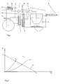
- Fig. 1 a schematic cross-sectional view of a vacuum cleaner is shown.
- a bagless vacuum cleaner 1 is shown in which instead of a Dust bag a centrifugal separator 2 is provided in the form of a cyclone as the first filter stage.
- a fine dust filter 3 is arranged in the vacuum cleaner 1, which is arranged upstream of the drive motor 4 with the fan 5.
- the drive motor 4 is controlled by the controller 6, in which the transmitter can be located.
- a memory 7 can be provided in the controller 6, in which software for the evaluation electronics, actual values, setpoint values, reference values and / or indicator values can be stored and read out of the memory 7.
- the vacuum cleaner 1 has an actuator 8, which in the embodiment represents a kind of three-way valve, with the depending on the switching position of the main flow path 9 to the centrifugal separator 2 can be shut off and an opening for supplying secondary air 10 to open.
- an actuator 8 which is connected to the controller 6, a plurality of actuators 8 may be provided which individually open the main flow path 9 and / or the opening for supplying secondary air 10 and / or close.
- the actuator 8 may be manually or motorized adjustable, and it may be functionally connected to the transmitter. In particular in the form of an automatic operation.
- the actuator 8 is arranged in the flow direction of the suction air through the vacuum cleaner 1 seen before the fine dust filter 3.
- the Nachorder the actuator 8 behind the centrifugal separator 2 ensures that the secondary air 10 can flow without disturbing influences by other components of the vacuum cleaner 1, in particular Staubsammelorgane, in the fine dust filter 3 and from there into the downstream fan 5. From the blower 5, the sucked air is blown back to the outside air, as needed with an additional blow-out. Depending on the degree of filling of the fine dust filter 3, more or less air can be drawn through the fine dust filter 3 by the blower 5 for the same power. The fuller the fine dust filter 3 is, the less air flows at the same drive power of the drive motor 4 through the fine dust filter 3 through, and because of the lower air flow capacity of the fan 5 this runs at a then increased speed. The speed of the fan 5 increases the more, the more the fine dust filter 3 is full.
- the vacuum cleaner 1 may be provided instead of or in addition to the centrifugal separator 2 with a conventional dust bag.
- centrifugal separator 2 may also be arranged a plurality of centrifugal separators 2 arranged one behind the other in a vacuum cleaner 1.
- actuator with secondary air 10 can be supplied to thereby measure the degree of filling of a conventional dust bag can.
- the flow path from conventional dust bag to the blower 5 is designed so that there are no variable flow resistances such as particulate matter filter in order to be able to measure as accurately as possible the degree of filling on the evaluation of the speed of the drive motor.
- the air duct for guiding the aspirated air during a measurement may also be separate from the usual air duct for aspirated air.
- the actuator 8 can be reset manually or by motor to the normal operating state by the main flow path 9 from the centrifugal separator 2 and a conventional dust bag unhindered to the fine dust filter 3, the fan 5 to the exhaust opening of the vacuum cleaner 1 runs.
- the vacuum cleaner 1 may be equipped with a display device 11, with the degree of filling of the monitored Staubabscheide- and collecting member can be displayed.
- the display device 11 may be, for example, a traffic light, which shows a green light in the case of an uncritical filling state, a yellow light in the case of a filling state approaching the filling limit, and a red light in the case of a full state.
- the filling state can also be displayed via a single LED that can light up in different colors, or the display is alphanumeric or via symbols on a display or other display device.
- the fine dust filter 3 has an individual identification which can be evaluated by the evaluation electronics located in the control 6.
- the particulate matter filter 3 has a transponder 12, the signal from a transponder receiving device 13 is receivable.
- the transponder receiving device 13 is connected to the controller 6 such that the value transmitted by the transponder 12 can be processed by the evaluation electronics.
- a number of the inserted particulate matter filter 3 which is comparable to other numbers, in particular with the number of the previous fine dust filter, transmitted, or it is data representing a reference value, a desired value and / or another value, so that these data need not be determined separately according to this embodiment of the invention, but the evaluation are supplied via the fine dust filter 3.
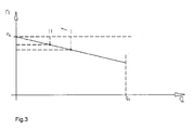
- FIG. 2 shows a flow chart in which the flow resistances R represent parabolas that form the system operating points I, II, etc. in section with the blower characteristic GBL.
- the speed of the drive motor 4 forms in principle or approximately a falling straight line, as in Fig. 3 is shown.
- the Speed of the drive motor 4 As the flow increases, the Speed of the drive motor 4.
- a filling fine dust filter 3 causes in principle a movement of the load characteristic from the operating point I to the operating point II.
- the evaluation of the controller 6 can be switched to a detection mode.
- the circuit in the determination mode can be triggered manually, automatically - for example via a time clock - or by a signal of the transponder receiving device 13 described above.
- the absolute and / or relative speed of the drive motor can be determined as the actual value after switching on the drive motor 4. Since the empty particulate matter filter 3 or the empty Staubabscheide- and collecting organ of the suction air flowing through hardly opposes resistance, the fan 5 must provide a relatively high flow rate, whereby the speed of the drive motor 4 is pressed.
- the measurement of the rotational speed of the drive motor 4 is performed in a power stage which is reproducible for later determination and evaluation processes.
- the actual value can be determined for example in a higher or the maximum power level of the drive motor 4, because here the speed differences are clearly visible.
- the vacuum cleaner 1 provided with an actuator 8, as shown in the Fig. 1 is shown, so the evaluation for detecting the rotational speed of the drive motor 4 close the main flow path 9 and open the opening for supplying secondary air 10, in particular in an automated process that is controlled by the transmitter.
- the determined actual value for the rotational speed of the drive motor 4 can be stored in the memory 7 after determination, for example as a reference value for later comparisons.
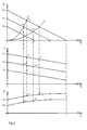
- p stands for the negative pressure
- n the rotational speed
- P the power input
- q the flow.
- FIG. 4a are shown with P1, P2 and P3 different power levels of the blower 5.
- the blower stage P1 is the exemplified selected operating point I, for which results in an empty particulate matter filter 3 a the operating point I corresponding ratio between the negative pressure in the vacuum cleaner 1 and the resulting flow q.
- the fine dust filter 3 is filled with dust, the flow resistance through the fine dust filter 3 increases.
- the negative pressure in the vacuum cleaner 1 increases, and the flow rate q decreases, so that, for example, the operating point II in the power plane P1 at a particulate matter filter 3 filling FIG. 4a established.
- the operating point III which migrates in a filled particulate matter filter 3 in the working point IV.
- Fig. 4b the speed curves for the speed n of the drive motor 4 are shown. From the diagram in Fig. 4b It can be seen that the speed n of the drive motor 4 increases when the vacuum cleaner 1 is operated instead of the operating point I with empty particulate filter 3 at the operating point II with a fuller particulate matter filter III. The same applies to the in Fig. 4b shown power level P2.
- Fig. 4c From the Fig. 4c can be seen that the power P of the drive motor 4 is reduced when the vacuum cleaner 1 is operated in the operating points II and IV instead of the operating points I and III respectively.
- the Fig. 4 thus makes it clear how, depending on the degree of filling of the fine dust filter 3, the rotational speeds, the negative pressure, the intake capacity and flow rates in the vacuum cleaner 1 change.
- the degree of filling of the fine dust filter 3 can be determined with sufficient accuracy by the size of the difference and / or relation to the reference value in the operating point I. It is possible to determine new actual values as a function of the operating time of the vacuum cleaner 1 at regular time intervals and / or at each switching on and / or off of the vacuum cleaner 1. Since relative statements can provide more reliable information than absolute numerical values, it is not always necessary to compare absolute numbers directly with each other in a comparison. In the comparison, it is not always necessary to refer to the reference value when the fine dust filter 3 is empty; other reference variables are also possible according to the invention.
- Fig. 4 are shown three power levels P1, P2 and P3, but it is understood that more or less power levels can be provided or the drive motor 4 is continuously variable. In order to carry out a comparison, it is important that the values for the operating points to be compared correspond at least approximately to a comparable level of performance.
- all or selected further power levels which may be correspondingly adjustable, are controlled by the evaluation electronics and associated reference values are determined.
- individual, several points or the entire load characteristic of the fine dust filter 3 can be imaged.
- the difference in the recording power of the drive motor 4 in the individual operating points is included in the evaluation of the evaluation in the comparison of the actual value with the reference value.
- all or certain selected stored reference values in the memory 7 are reset after the detection of the insertion of a new fine dust filter 3. The next time you turn on the bagless vacuum cleaner 1 can be determined by the transmitter again a new reference value for the speed.
- a brushless drive motor 4 can be used, in particular with a reluctance motor, since these drives do not require any additional speed sensors and consequently enable a cost-effective implementation of the method.
- the recording power can be reproduced for example by converter-specific variables.
- Another advantage is the fact that these drives require no exhaust filter due to the electronic commutator, so that the flow resistance of the particulate matter filter 3 can be determined very accurately. If vacuum cleaners 1 are used with universal motors, they should be equipped to implement the invention with suitable measuring sensors for determining the relevant reference values.
- the invention is not limited to the embodiment described above. It is not difficult for a person skilled in the art to adapt the invention to particular conditions of use in a manner which it considers suitable.
Landscapes
- Engineering & Computer Science (AREA)
- Mechanical Engineering (AREA)
- Electric Vacuum Cleaner (AREA)
- Filters For Electric Vacuum Cleaners (AREA)
Applications Claiming Priority (1)
| Application Number | Priority Date | Filing Date | Title |
|---|---|---|---|
| DE200810038893 DE102008038893A1 (de) | 2008-08-13 | 2008-08-13 | Verfahren und Vorrichtung zur Bestimmung des Füllgrades eines in einem Staubsauger angeordneten Sammelorgans |
Publications (3)
| Publication Number | Publication Date |
|---|---|
| EP2153768A2 true EP2153768A2 (fr) | 2010-02-17 |
| EP2153768A3 EP2153768A3 (fr) | 2012-02-08 |
| EP2153768B1 EP2153768B1 (fr) | 2014-07-02 |
Family
ID=41131681
Family Applications (1)
| Application Number | Title | Priority Date | Filing Date |
|---|---|---|---|
| EP20090010332 Not-in-force EP2153768B1 (fr) | 2008-08-13 | 2009-08-11 | Procédé et dispositif de détermination du niveau de remplissage d'un organe de collecte agencé dans un aspirateur |
Country Status (2)
| Country | Link |
|---|---|
| EP (1) | EP2153768B1 (fr) |
| DE (1) | DE102008038893A1 (fr) |
Cited By (3)
| Publication number | Priority date | Publication date | Assignee | Title |
|---|---|---|---|---|
| US20130008468A1 (en) * | 2011-07-08 | 2013-01-10 | Miele & Cie. Kg | Method for operating a vacuum cleaner having a cyclone separator and a vacuum cleaner having a cyclone separator |
| CN111493741A (zh) * | 2019-01-30 | 2020-08-07 | 北京奇虎科技有限公司 | 尘盒检测方法、装置、电子设备及计算机可读存储介质 |
| JP2022529172A (ja) * | 2019-04-23 | 2022-06-17 | ヒルティ アクチエンゲゼルシャフト | 真空清掃機器における清掃プロセスを制御するための方法、及び真空清掃機器 |
Families Citing this family (11)
| Publication number | Priority date | Publication date | Assignee | Title |
|---|---|---|---|---|
| DE102011079118B4 (de) | 2010-07-14 | 2019-03-07 | BSH Hausgeräte GmbH | Staubsauger |
| DE102012102631A1 (de) | 2012-03-27 | 2013-10-02 | Alfred Kärcher Gmbh & Co. Kg | Verfahren zum Einstellen eines Saugsystems, Verfahren zum Betreiben eines Saugsystems und Saugsystem |
| DE102012105142B4 (de) * | 2012-06-14 | 2020-03-05 | Miele & Cie. Kg | Leistungssteller für einen Staubsauger und Staubsauger mit einem solchen Leistungssteller |
| DE102015114668A1 (de) * | 2015-09-02 | 2017-03-02 | Alfred Kärcher Gmbh & Co. Kg | Saugvorrichtung und Verfahren zum Betreiben einer Saugvorrichtung |
| CN109475802B (zh) | 2016-04-15 | 2022-07-19 | 创科无线普通合伙 | 手持式真空吸尘器 |
| AU201712063S (en) | 2016-10-14 | 2017-04-26 | Tti Macao Commercial Offshore Ltd | Handheld vacuum cleaner |
| AU201712064S (en) | 2016-10-14 | 2017-04-27 | Tti Macao Commercial Offshore Ltd | Handheld vacuum cleaner |
| AU201812645S (en) | 2017-12-05 | 2018-07-31 | Tti Macao Commercial Offshore Ltd | Housing for a vacuum filter |
| CN217096845U (zh) | 2018-08-31 | 2022-08-02 | 米沃奇电动工具公司 | 电动工具 |
| DE102019009178B4 (de) | 2019-05-28 | 2023-11-23 | Vorwerk & Co. Interholding Gmbh | Verfahren zum Betrieb eines Sauggeräts und Sauggerät |
| DE102019114347B4 (de) * | 2019-05-28 | 2023-03-09 | Vorwerk & Co. Interholding Gmbh | Verfahren zum Betrieb eines Sauggeräts und Sauggerät |
Citations (1)
| Publication number | Priority date | Publication date | Assignee | Title |
|---|---|---|---|---|
| WO2007022959A2 (fr) | 2005-08-26 | 2007-03-01 | Miele & Cie. Kg | Procede pour traiter la poussiere et dispositifs pour executer un tel procede |
Family Cites Families (2)
| Publication number | Priority date | Publication date | Assignee | Title |
|---|---|---|---|---|
| DE102005045544A1 (de) * | 2005-09-23 | 2007-03-29 | Vorwerk & Co. Interholding Gmbh | Verfahren zum Generieren eines Signals zum Filterbeutelwechsel sowie Staubsauger mit einem Sauggebläse |
| US7823249B2 (en) * | 2006-01-05 | 2010-11-02 | The Scott Fetzer Company | Motor control for a vacuum cleaner |
-
2008
- 2008-08-13 DE DE200810038893 patent/DE102008038893A1/de not_active Ceased
-
2009
- 2009-08-11 EP EP20090010332 patent/EP2153768B1/fr not_active Not-in-force
Patent Citations (1)
| Publication number | Priority date | Publication date | Assignee | Title |
|---|---|---|---|---|
| WO2007022959A2 (fr) | 2005-08-26 | 2007-03-01 | Miele & Cie. Kg | Procede pour traiter la poussiere et dispositifs pour executer un tel procede |
Cited By (7)
| Publication number | Priority date | Publication date | Assignee | Title |
|---|---|---|---|---|
| US20130008468A1 (en) * | 2011-07-08 | 2013-01-10 | Miele & Cie. Kg | Method for operating a vacuum cleaner having a cyclone separator and a vacuum cleaner having a cyclone separator |
| EP2543302A3 (fr) * | 2011-07-08 | 2017-01-04 | Miele & Cie. KG | Procédé d'utilisation d'un aspirateur doté d'un séparateur à cyclone et aspirateur doté d'un séparateur à cyclone |
| US10076218B2 (en) * | 2011-07-08 | 2018-09-18 | Miele & Cie. Kg | Method for operating a vacuum cleaner having a cyclone separator and a vacuum cleaner having a cyclone separator |
| CN111493741A (zh) * | 2019-01-30 | 2020-08-07 | 北京奇虎科技有限公司 | 尘盒检测方法、装置、电子设备及计算机可读存储介质 |
| CN111493741B (zh) * | 2019-01-30 | 2023-02-17 | 北京奇虎科技有限公司 | 尘盒检测方法、装置、电子设备及计算机可读存储介质 |
| JP2022529172A (ja) * | 2019-04-23 | 2022-06-17 | ヒルティ アクチエンゲゼルシャフト | 真空清掃機器における清掃プロセスを制御するための方法、及び真空清掃機器 |
| US12357141B2 (en) | 2019-04-23 | 2025-07-15 | Hilti Aktiengesellschaft | Method for controlling a clearing process in a vacuum cleaning device, and vacuum cleaning device |
Also Published As
| Publication number | Publication date |
|---|---|
| DE102008038893A1 (de) | 2010-02-18 |
| EP2153768B1 (fr) | 2014-07-02 |
| EP2153768A3 (fr) | 2012-02-08 |
Similar Documents
| Publication | Publication Date | Title |
|---|---|---|
| EP2153768B1 (fr) | Procédé et dispositif de détermination du niveau de remplissage d'un organe de collecte agencé dans un aspirateur | |
| EP3119260B1 (fr) | Méthode pour nettoyer un filtre d'un aspirateur et l'aspirateur | |
| EP0373353B1 (fr) | Dispositif de régulation et d'indication de fonctionnement pour aspirateurs de poussières | |
| EP3120744B1 (fr) | Dispositif de commande de nettoyage d'une unite de filtre pour aspirateur | |
| DE102007025388A1 (de) | Verfahren zum Betreiben eines Staubsaugers | |
| EP2543302B1 (fr) | Procédé d'utilisation d'un aspirateur doté d'un séparateur à cyclone et aspirateur doté d'un séparateur à cyclone | |
| EP2765359B1 (fr) | Procédé de surveillance d'un flux d'air dans une gaine d'aération | |
| EP2595522B1 (fr) | Procédé et dispositif de commande de performance d'un moteur de soufflerie pour un aspirateur | |
| EP4179265B1 (fr) | Procédé et système de ventilateur pour vérifier un point de fonctionnement actuel d'une unité de ventilateur | |
| DE102009036409A1 (de) | Ringspinnmaschine | |
| WO2013144149A1 (fr) | Procédé de réglage d'un système d'aspiration, procédé servant à faire fonctionner un système d'aspiration et système d'aspiration | |
| EP2946711B1 (fr) | Procédé de fonctionnement d'un aspirateur et aspirateur | |
| EP3573737B1 (fr) | Procédé de détection d'un colmatage de filtre | |
| DE102007036170A1 (de) | Verfahren und Vorrichtung zum Bestimmen der Menge von Staubpartikeln, insbesondere in einem Staubsammelroboter, sowie Staubsammelgerät mit einer solchen Vorrichtung | |
| WO2012013483A2 (fr) | Dispositif et procédé pour faire fonctionner un aspirateur | |
| EP2505115B1 (fr) | Aspirateur et procédé destiné au fonctionnement en fonction de la durée de fonctionnement d'un aspirateur | |
| DE102011050260B4 (de) | Staubsauger und Verfahren zur Auswertung eines Partikelsignals in einem Staubsauger | |
| DE102014005384A1 (de) | Sauggerät und Verfahren zum Betreiben eines Sauggeräts | |
| EP4212082B1 (fr) | Aspirateur, de préférence aspirateur à main | |
| DE19908378A1 (de) | Filtereinrichtung für eine Textilmaschine | |
| DE102021200388B4 (de) | Einlernfunktion für Staubsauger mit Motordüsen | |
| EP3821778B1 (fr) | Aspirateur et procédé de fonctionnement d'un aspirateur | |
| EP0098441B1 (fr) | Installation avec au moins un broyeur | |
| DE4304264A1 (de) | Eigendiagnose für einen Staubsauger und Verfahren zu deren Betrieb | |
| DE102014010886A1 (de) | Filterelement für eine Klimaanlage eines Kraftwagens, Klimanlage für einen Kraftwagen sowie Verfahren zum Betreiben einer Klimaanlage |
Legal Events
| Date | Code | Title | Description |
|---|---|---|---|
| PUAI | Public reference made under article 153(3) epc to a published international application that has entered the european phase |
Free format text: ORIGINAL CODE: 0009012 |
|
| AK | Designated contracting states |
Kind code of ref document: A2 Designated state(s): AT BE BG CH CY CZ DE DK EE ES FI FR GB GR HR HU IE IS IT LI LT LU LV MC MK MT NL NO PL PT RO SE SI SK SM TR |
|
| AX | Request for extension of the european patent |
Extension state: AL BA RS |
|
| PUAL | Search report despatched |
Free format text: ORIGINAL CODE: 0009013 |
|
| AK | Designated contracting states |
Kind code of ref document: A3 Designated state(s): AT BE BG CH CY CZ DE DK EE ES FI FR GB GR HR HU IE IS IT LI LT LU LV MC MK MT NL NO PL PT RO SE SI SK SM TR |
|
| AX | Request for extension of the european patent |
Extension state: AL BA RS |
|
| RIC1 | Information provided on ipc code assigned before grant |
Ipc: A47L 9/19 20060101ALI20120105BHEP Ipc: A47L 9/10 20060101AFI20120105BHEP Ipc: A47L 9/16 20060101ALI20120105BHEP Ipc: A47L 9/12 20060101ALN20120105BHEP |
|
| 17P | Request for examination filed |
Effective date: 20120803 |
|
| RIC1 | Information provided on ipc code assigned before grant |
Ipc: A47L 9/10 20060101AFI20140207BHEP Ipc: A47L 9/12 20060101ALN20140207BHEP Ipc: A47L 9/16 20060101ALI20140207BHEP Ipc: A47L 9/19 20060101ALI20140207BHEP |
|
| GRAP | Despatch of communication of intention to grant a patent |
Free format text: ORIGINAL CODE: EPIDOSNIGR1 |
|
| INTG | Intention to grant announced |
Effective date: 20140324 |
|
| GRAS | Grant fee paid |
Free format text: ORIGINAL CODE: EPIDOSNIGR3 |
|
| GRAA | (expected) grant |
Free format text: ORIGINAL CODE: 0009210 |
|
| AK | Designated contracting states |
Kind code of ref document: B1 Designated state(s): AT BE BG CH CY CZ DE DK EE ES FI FR GB GR HR HU IE IS IT LI LT LU LV MC MK MT NL NO PL PT RO SE SI SK SM TR |
|
| REG | Reference to a national code |
Ref country code: GB Ref legal event code: FG4D Free format text: NOT ENGLISH |
|
| REG | Reference to a national code |
Ref country code: CH Ref legal event code: EP Ref country code: AT Ref legal event code: REF Ref document number: 675441 Country of ref document: AT Kind code of ref document: T Effective date: 20140715 |
|
| REG | Reference to a national code |
Ref country code: IE Ref legal event code: FG4D Free format text: LANGUAGE OF EP DOCUMENT: GERMAN |
|
| REG | Reference to a national code |
Ref country code: DE Ref legal event code: R096 Ref document number: 502009009599 Country of ref document: DE Effective date: 20140814 |
|
| REG | Reference to a national code |
Ref country code: DE Ref legal event code: R084 Ref document number: 502009009599 Country of ref document: DE Effective date: 20140717 |
|
| REG | Reference to a national code |
Ref country code: GB Ref legal event code: 746 Effective date: 20140901 |
|
| REG | Reference to a national code |
Ref country code: NL Ref legal event code: VDEP Effective date: 20140702 |
|
| REG | Reference to a national code |
Ref country code: LT Ref legal event code: MG4D |
|
| PG25 | Lapsed in a contracting state [announced via postgrant information from national office to epo] |
Ref country code: ES Free format text: LAPSE BECAUSE OF FAILURE TO SUBMIT A TRANSLATION OF THE DESCRIPTION OR TO PAY THE FEE WITHIN THE PRESCRIBED TIME-LIMIT Effective date: 20140702 Ref country code: BG Free format text: LAPSE BECAUSE OF FAILURE TO SUBMIT A TRANSLATION OF THE DESCRIPTION OR TO PAY THE FEE WITHIN THE PRESCRIBED TIME-LIMIT Effective date: 20141002 Ref country code: GR Free format text: LAPSE BECAUSE OF FAILURE TO SUBMIT A TRANSLATION OF THE DESCRIPTION OR TO PAY THE FEE WITHIN THE PRESCRIBED TIME-LIMIT Effective date: 20141003 Ref country code: NO Free format text: LAPSE BECAUSE OF FAILURE TO SUBMIT A TRANSLATION OF THE DESCRIPTION OR TO PAY THE FEE WITHIN THE PRESCRIBED TIME-LIMIT Effective date: 20141002 Ref country code: CZ Free format text: LAPSE BECAUSE OF FAILURE TO SUBMIT A TRANSLATION OF THE DESCRIPTION OR TO PAY THE FEE WITHIN THE PRESCRIBED TIME-LIMIT Effective date: 20140702 Ref country code: PT Free format text: LAPSE BECAUSE OF FAILURE TO SUBMIT A TRANSLATION OF THE DESCRIPTION OR TO PAY THE FEE WITHIN THE PRESCRIBED TIME-LIMIT Effective date: 20141103 Ref country code: LT Free format text: LAPSE BECAUSE OF FAILURE TO SUBMIT A TRANSLATION OF THE DESCRIPTION OR TO PAY THE FEE WITHIN THE PRESCRIBED TIME-LIMIT Effective date: 20140702 Ref country code: SE Free format text: LAPSE BECAUSE OF FAILURE TO SUBMIT A TRANSLATION OF THE DESCRIPTION OR TO PAY THE FEE WITHIN THE PRESCRIBED TIME-LIMIT Effective date: 20140702 Ref country code: FI Free format text: LAPSE BECAUSE OF FAILURE TO SUBMIT A TRANSLATION OF THE DESCRIPTION OR TO PAY THE FEE WITHIN THE PRESCRIBED TIME-LIMIT Effective date: 20140702 |
|
| PG25 | Lapsed in a contracting state [announced via postgrant information from national office to epo] |
Ref country code: CY Free format text: LAPSE BECAUSE OF FAILURE TO SUBMIT A TRANSLATION OF THE DESCRIPTION OR TO PAY THE FEE WITHIN THE PRESCRIBED TIME-LIMIT Effective date: 20140702 Ref country code: LV Free format text: LAPSE BECAUSE OF FAILURE TO SUBMIT A TRANSLATION OF THE DESCRIPTION OR TO PAY THE FEE WITHIN THE PRESCRIBED TIME-LIMIT Effective date: 20140702 Ref country code: IS Free format text: LAPSE BECAUSE OF FAILURE TO SUBMIT A TRANSLATION OF THE DESCRIPTION OR TO PAY THE FEE WITHIN THE PRESCRIBED TIME-LIMIT Effective date: 20141102 Ref country code: HR Free format text: LAPSE BECAUSE OF FAILURE TO SUBMIT A TRANSLATION OF THE DESCRIPTION OR TO PAY THE FEE WITHIN THE PRESCRIBED TIME-LIMIT Effective date: 20140702 Ref country code: NL Free format text: LAPSE BECAUSE OF FAILURE TO SUBMIT A TRANSLATION OF THE DESCRIPTION OR TO PAY THE FEE WITHIN THE PRESCRIBED TIME-LIMIT Effective date: 20140702 Ref country code: PL Free format text: LAPSE BECAUSE OF FAILURE TO SUBMIT A TRANSLATION OF THE DESCRIPTION OR TO PAY THE FEE WITHIN THE PRESCRIBED TIME-LIMIT Effective date: 20140702 |
|
| REG | Reference to a national code |
Ref country code: CH Ref legal event code: PL |
|
| REG | Reference to a national code |
Ref country code: DE Ref legal event code: R097 Ref document number: 502009009599 Country of ref document: DE |
|
| PG25 | Lapsed in a contracting state [announced via postgrant information from national office to epo] |
Ref country code: RO Free format text: LAPSE BECAUSE OF FAILURE TO SUBMIT A TRANSLATION OF THE DESCRIPTION OR TO PAY THE FEE WITHIN THE PRESCRIBED TIME-LIMIT Effective date: 20140702 Ref country code: MC Free format text: LAPSE BECAUSE OF FAILURE TO SUBMIT A TRANSLATION OF THE DESCRIPTION OR TO PAY THE FEE WITHIN THE PRESCRIBED TIME-LIMIT Effective date: 20140702 Ref country code: EE Free format text: LAPSE BECAUSE OF FAILURE TO SUBMIT A TRANSLATION OF THE DESCRIPTION OR TO PAY THE FEE WITHIN THE PRESCRIBED TIME-LIMIT Effective date: 20140702 Ref country code: DK Free format text: LAPSE BECAUSE OF FAILURE TO SUBMIT A TRANSLATION OF THE DESCRIPTION OR TO PAY THE FEE WITHIN THE PRESCRIBED TIME-LIMIT Effective date: 20140702 Ref country code: LI Free format text: LAPSE BECAUSE OF NON-PAYMENT OF DUE FEES Effective date: 20140831 Ref country code: CH Free format text: LAPSE BECAUSE OF NON-PAYMENT OF DUE FEES Effective date: 20140831 Ref country code: SK Free format text: LAPSE BECAUSE OF FAILURE TO SUBMIT A TRANSLATION OF THE DESCRIPTION OR TO PAY THE FEE WITHIN THE PRESCRIBED TIME-LIMIT Effective date: 20140702 Ref country code: BE Free format text: LAPSE BECAUSE OF NON-PAYMENT OF DUE FEES Effective date: 20140831 |
|
| PLBE | No opposition filed within time limit |
Free format text: ORIGINAL CODE: 0009261 |
|
| STAA | Information on the status of an ep patent application or granted ep patent |
Free format text: STATUS: NO OPPOSITION FILED WITHIN TIME LIMIT |
|
| REG | Reference to a national code |
Ref country code: IE Ref legal event code: MM4A |
|
| 26N | No opposition filed |
Effective date: 20150407 |
|
| PG25 | Lapsed in a contracting state [announced via postgrant information from national office to epo] |
Ref country code: IE Free format text: LAPSE BECAUSE OF NON-PAYMENT OF DUE FEES Effective date: 20140811 |
|
| REG | Reference to a national code |
Ref country code: AT Ref legal event code: MM01 Ref document number: 675441 Country of ref document: AT Kind code of ref document: T Effective date: 20140811 |
|
| PG25 | Lapsed in a contracting state [announced via postgrant information from national office to epo] |
Ref country code: AT Free format text: LAPSE BECAUSE OF NON-PAYMENT OF DUE FEES Effective date: 20140811 Ref country code: SI Free format text: LAPSE BECAUSE OF FAILURE TO SUBMIT A TRANSLATION OF THE DESCRIPTION OR TO PAY THE FEE WITHIN THE PRESCRIBED TIME-LIMIT Effective date: 20140702 |
|
| PG25 | Lapsed in a contracting state [announced via postgrant information from national office to epo] |
Ref country code: SM Free format text: LAPSE BECAUSE OF FAILURE TO SUBMIT A TRANSLATION OF THE DESCRIPTION OR TO PAY THE FEE WITHIN THE PRESCRIBED TIME-LIMIT Effective date: 20140702 |
|
| PG25 | Lapsed in a contracting state [announced via postgrant information from national office to epo] |
Ref country code: MT Free format text: LAPSE BECAUSE OF FAILURE TO SUBMIT A TRANSLATION OF THE DESCRIPTION OR TO PAY THE FEE WITHIN THE PRESCRIBED TIME-LIMIT Effective date: 20140702 |
|
| PG25 | Lapsed in a contracting state [announced via postgrant information from national office to epo] |
Ref country code: TR Free format text: LAPSE BECAUSE OF FAILURE TO SUBMIT A TRANSLATION OF THE DESCRIPTION OR TO PAY THE FEE WITHIN THE PRESCRIBED TIME-LIMIT Effective date: 20140702 Ref country code: HU Free format text: LAPSE BECAUSE OF FAILURE TO SUBMIT A TRANSLATION OF THE DESCRIPTION OR TO PAY THE FEE WITHIN THE PRESCRIBED TIME-LIMIT; INVALID AB INITIO Effective date: 20090811 Ref country code: LU Free format text: LAPSE BECAUSE OF NON-PAYMENT OF DUE FEES Effective date: 20140811 |
|
| REG | Reference to a national code |
Ref country code: FR Ref legal event code: PLFP Year of fee payment: 8 |
|
| REG | Reference to a national code |
Ref country code: FR Ref legal event code: PLFP Year of fee payment: 9 |
|
| PG25 | Lapsed in a contracting state [announced via postgrant information from national office to epo] |
Ref country code: MK Free format text: LAPSE BECAUSE OF FAILURE TO SUBMIT A TRANSLATION OF THE DESCRIPTION OR TO PAY THE FEE WITHIN THE PRESCRIBED TIME-LIMIT Effective date: 20140702 |
|
| REG | Reference to a national code |
Ref country code: FR Ref legal event code: PLFP Year of fee payment: 10 |
|
| PGFP | Annual fee paid to national office [announced via postgrant information from national office to epo] |
Ref country code: IT Payment date: 20220819 Year of fee payment: 14 Ref country code: GB Payment date: 20220823 Year of fee payment: 14 Ref country code: DE Payment date: 20220831 Year of fee payment: 14 |
|
| PGFP | Annual fee paid to national office [announced via postgrant information from national office to epo] |
Ref country code: FR Payment date: 20220824 Year of fee payment: 14 |
|
| REG | Reference to a national code |
Ref country code: DE Ref legal event code: R119 Ref document number: 502009009599 Country of ref document: DE |
|
| GBPC | Gb: european patent ceased through non-payment of renewal fee |
Effective date: 20230811 |
|
| PG25 | Lapsed in a contracting state [announced via postgrant information from national office to epo] |
Ref country code: GB Free format text: LAPSE BECAUSE OF NON-PAYMENT OF DUE FEES Effective date: 20230811 |
|
| PG25 | Lapsed in a contracting state [announced via postgrant information from national office to epo] |
Ref country code: IT Free format text: LAPSE BECAUSE OF NON-PAYMENT OF DUE FEES Effective date: 20230811 Ref country code: GB Free format text: LAPSE BECAUSE OF NON-PAYMENT OF DUE FEES Effective date: 20230811 Ref country code: FR Free format text: LAPSE BECAUSE OF NON-PAYMENT OF DUE FEES Effective date: 20230831 Ref country code: DE Free format text: LAPSE BECAUSE OF NON-PAYMENT OF DUE FEES Effective date: 20240301 |