EP2153887A2 - Dispositif de malaxage avec transmission de données sans contact - Google Patents
Dispositif de malaxage avec transmission de données sans contact Download PDFInfo
- Publication number
- EP2153887A2 EP2153887A2 EP09008403A EP09008403A EP2153887A2 EP 2153887 A2 EP2153887 A2 EP 2153887A2 EP 09008403 A EP09008403 A EP 09008403A EP 09008403 A EP09008403 A EP 09008403A EP 2153887 A2 EP2153887 A2 EP 2153887A2
- Authority
- EP
- European Patent Office
- Prior art keywords
- stirring
- data
- receiving unit
- laboratory stirrer
- measuring
- Prior art date
- Legal status (The legal status is an assumption and is not a legal conclusion. Google has not performed a legal analysis and makes no representation as to the accuracy of the status listed.)
- Withdrawn
Links
Images




Classifications
-
- G—PHYSICS
- G08—SIGNALLING
- G08C—TRANSMISSION SYSTEMS FOR MEASURED VALUES, CONTROL OR SIMILAR SIGNALS
- G08C17/00—Arrangements for transmitting signals characterised by the use of a wireless electrical link
-
- B—PERFORMING OPERATIONS; TRANSPORTING
- B01—PHYSICAL OR CHEMICAL PROCESSES OR APPARATUS IN GENERAL
- B01F—MIXING, e.g. DISSOLVING, EMULSIFYING OR DISPERSING
- B01F27/00—Mixers with rotary stirring devices in fixed receptacles; Kneaders
- B01F27/80—Mixers with rotary stirring devices in fixed receptacles; Kneaders with stirrers rotating about a substantially vertical axis
- B01F27/805—Mixers with rotary stirring devices in fixed receptacles; Kneaders with stirrers rotating about a substantially vertical axis wherein the stirrers or the receptacles are moved in order to bring them into operative position; Means for fixing the receptacle
-
- B—PERFORMING OPERATIONS; TRANSPORTING
- B01—PHYSICAL OR CHEMICAL PROCESSES OR APPARATUS IN GENERAL
- B01F—MIXING, e.g. DISSOLVING, EMULSIFYING OR DISPERSING
- B01F35/00—Accessories for mixers; Auxiliary operations or auxiliary devices; Parts or details of general application
- B01F35/20—Measuring; Control or regulation
- B01F35/21—Measuring
- B01F35/211—Measuring of the operational parameters
- B01F35/2115—Temperature
-
- B—PERFORMING OPERATIONS; TRANSPORTING
- B01—PHYSICAL OR CHEMICAL PROCESSES OR APPARATUS IN GENERAL
- B01F—MIXING, e.g. DISSOLVING, EMULSIFYING OR DISPERSING
- B01F35/00—Accessories for mixers; Auxiliary operations or auxiliary devices; Parts or details of general application
- B01F35/20—Measuring; Control or regulation
- B01F35/21—Measuring
- B01F35/213—Measuring of the properties of the mixtures, e.g. temperature, density or colour
-
- B—PERFORMING OPERATIONS; TRANSPORTING
- B01—PHYSICAL OR CHEMICAL PROCESSES OR APPARATUS IN GENERAL
- B01F—MIXING, e.g. DISSOLVING, EMULSIFYING OR DISPERSING
- B01F35/00—Accessories for mixers; Auxiliary operations or auxiliary devices; Parts or details of general application
- B01F35/20—Measuring; Control or regulation
- B01F35/21—Measuring
- B01F35/214—Measuring characterised by the means for measuring
- B01F35/2142—Measuring characterised by the means for measuring using wireless sensors introduced in the mixture, e.g. transponders or RFID tags, for measuring the parameters of the mixture or components to be mixed
-
- G—PHYSICS
- G01—MEASURING; TESTING
- G01K—MEASURING TEMPERATURE; MEASURING QUANTITY OF HEAT; THERMALLY-SENSITIVE ELEMENTS NOT OTHERWISE PROVIDED FOR
- G01K1/00—Details of thermometers not specially adapted for particular types of thermometer
- G01K1/02—Means for indicating or recording specially adapted for thermometers
- G01K1/024—Means for indicating or recording specially adapted for thermometers for remote indication
-
- G—PHYSICS
- G01—MEASURING; TESTING
- G01K—MEASURING TEMPERATURE; MEASURING QUANTITY OF HEAT; THERMALLY-SENSITIVE ELEMENTS NOT OTHERWISE PROVIDED FOR
- G01K13/00—Thermometers specially adapted for specific purposes
- G01K13/04—Thermometers specially adapted for specific purposes for measuring temperature of moving solid bodies
- G01K13/08—Thermometers specially adapted for specific purposes for measuring temperature of moving solid bodies in rotary movement
-
- B—PERFORMING OPERATIONS; TRANSPORTING
- B01—PHYSICAL OR CHEMICAL PROCESSES OR APPARATUS IN GENERAL
- B01L—CHEMICAL OR PHYSICAL LABORATORY APPARATUS FOR GENERAL USE
- B01L7/00—Heating or cooling apparatus; Heat insulating devices
Definitions
- the present invention relates to a laboratory stirrer, in particular an overhead stirrer, with an agitator and with a stirrer driven by the stirrer, intended for immersion in a stirring medium to be stirred medium.
- Laboratory stirrers with a stirrer are used in laboratories to mix a medium in a container.
- a medium is agitated by means of a stirring tool located on a stirring shaft in order to achieve a uniform material distribution.
- the medium to be stirred may be solid or liquid (particulate).
- solids can be dissolved in liquids or different liquids mixed together.
- a so-called overhead stirrer is used for this purpose, in which the stirrer is arranged above the container and the stirrer shaft extends vertically downwards with the stirrer.
- the stirring In addition to a uniform distribution of material to be achieved by the stirring and a uniform temperature distribution within the medium. This is particularly important if the medium is heated while stirring, for example, heated. In this case, the temperature of the medium to be stirred, in particular a liquid, is measured during the stirring process. For this purpose, a temperature sensor is usually immersed in the medium, with which the temperature is determined.
- stirring within the meaning of the invention also includes mixing, homogenizing, suspending, gassing and circulating media. In the following, without restriction, only talking of stirring.
- the object of the present invention is to avoid the disadvantages of the laboratory stirrers known from the prior art.
- the present object is achieved by a laboratory stirrer with the features of claim 1, and in particular by the fact that the stirrer is provided with at least one measuring sensor for measuring measured data of a measured variable of the medium, wherein the stirrer is provided with a measuring circuit comprising a data transmission device in order to transfer the measurement data contactlessly to a receiving unit which does not rotate with the stirring element.
- the inventive laboratory stirrer has the advantage that no additional or separate measuring sensor is necessary for measuring the measured variable of the medium to be stirred or mixed, since the stirring element is already provided with a measuring sensor. Consequently, no separate holder for the measuring sensor must be provided.
- the handling of a laboratory device comprising the laboratory stirrer and a container with the medium to be stirred or mixed is simplified because no additional or separate sensor must be placed.
- the sensor is damaged by a stirring element or stirring tool of the stirring element, for example one or more stirring blades, or that the sensor hinders the stirring element.
- the container need not have additional feedthrough.
- the measuring sensor can be integrated in the stirring element.
- the measuring sensor can for example be mounted on the outside of the stirring element or be arranged inside the stirring element.
- the measuring sensor is supported by the stirring element.
- the medium to be stirred may be a liquid, but also other media such as highly viscous media, gases, gels or powdery substances.
- the present invention can be realized with any stirrer or stirrer.
- the stirring element is provided with a measuring circuit connected in particular to the measuring sensor, which comprises a data transmission device in order to transmit the measured data to a receiving unit which does not rotate with the stirring element, wherein the measured data can be transmitted from the data transmission device to the receiving unit.
- the measured data can be processed and / or digitized in the measuring circuit.
- the receiving unit is preferably part of the laboratory stirrer and / or stationary, stationary or fixed to the housing in the laboratory stirrer.
- energy and / or data from a coupling device in particular the receiving unit or a coupling device of the receiving unit, can be transmitted to the measuring circuit.
- the measurement data can be transmitted without contact or contactlessly from the data transmission device to the receiving unit.
- the measurement data can also not be transmitted without contact or contactless, for example by means of a slip ring or sliding contact.
- no measuring circuit as explained above, is necessary.
- the energy and / or the data are contactless transferable from the coupling device to the measuring circuit.
- the non-contact transmission of measurement data, energy and / or data can prevent slip rings or sliding contacts that are susceptible to wear, so that reliable and safe transmission and, in this respect, maintenance-free operation are possible.
- the agitator preferably comprises a holder which can be driven in rotation by a drive unit for holding the stirring element, in particular during stirring, wherein the holder is designed for exchangeable holding of the stirring element.
- the drive unit is arranged within a stirrer housing.
- the laboratory stirrer is adapted for use with laboratory scale containers.
- the laboratory stirrer is preferably for stirring volumes of up to 2001, in particular up to 1001, in particular up to 501, in particular up to 251, in particular up to 101, in particular up to 51, in particular up to 31, in particular up to 1.51, suitable or intended.
- a container receiving the medium to be stirred can have a capacity with the stated volumes.
- any measuring sensor is suitable which can measure measured data of a measured variable of the medium directly or indirectly.
- the stirring element can be provided with a plurality of, in particular different, measuring sensors.
- the at least one measuring sensor is a temperature sensor for measuring the temperature of the medium or the temperature distribution within the medium.
- the determined measurement data are then temperature data, which are determined by the temperature sensor.
- Temperature sensors used in the laboratory are usually designed as resistance sensors.
- a sliding contact has the property that it - depending on the state and degree of wear - varying resistance values.
- a contactless measurement data transmission is therefore particularly advantageous with regard to the measurement accuracy of the sensor in the case of a temperature sensor provided on the stirring element.
- the measuring sensor or one of the measuring sensors may comprise a strain gauge in order to determine the torque of the stirring element, by means of which, in particular, the viscosity of the medium can be measured.
- the determined elongation is an intermediate variable of the measured variable viscosity of the medium.
- the stirrer may be provided with a measuring sensor for measuring the conductivity of the medium or the pH of the medium, wherein in the pH measurement of the respective measuring sensor is touched by the medium, in particular flows around.
- the stirring element in particular in the region of the measuring sensor, openings such as slots or holes have.
- the receiving unit and the stirrer can be arranged in a common housing.
- the measuring sensor can be arranged on the end of the stirring element intended for immersion in the medium to be stirred.
- the stirring member comprises a stirring shaft, wherein preferably the stirring shaft is designed as a hollow shaft, in the interior of which the measuring sensor is arranged.
- the aforementioned measuring circuit can also be arranged in the interior of the hollow shaft.
- the stirrer may additionally comprise a stirring element, in particular one or more stirring vanes, wherein preferably the stirring element is replaceably attachable to the stirrer shaft.
- the exchangeability or interchangeability of the stirring element allows an adaptation of the laboratory stirrer, for example, to the stirring task or the toughness of the medium.
- the data transmission device is designed for the digital transmission of the measured data. If the measurement data are already digitized in the measurement circuit, the digital data can be transmitted in digital form from the data transmission device to the receiving unit. In this way, a robust and less error-prone transfer can be performed.
- the measurement circuit may comprise a coil.
- the coil is preferably provided on the end of the stirring element opposite the end intended for immersion in the medium to be stirred. Further preferably, the stirring member in the region of the coil of a non-magnetic material.
- the coil can cooperate with a magnetic field which is generated by the receiving unit.
- the stirring element can be plugged into a holder for holding the stirring element such that its region having the coil, in particular its end having the coil, projects beyond the holder in the axial direction.
- the receiving unit may comprise a coil for generating a magnetic field.
- the coil for generating an alternating magnetic field is connected to a feed current electronics, which feeds an alternating current into the coil.
- the measured data can be transmitted inductively, in particular by means of load modulation, from the data transmission device to the receiving unit.
- the measured data can also be transferred optically from the data transmission device to the receiving unit, wherein the data transmission device comprises a light transmitter and the receiving unit comprises a light receiver which is arranged opposite the light transmitter.
- the energy and / or the data can also be transmitted inductively from the coupling device to the measuring circuit.
- the energy and / or the data may be optically transferable from the coupling device to the measuring circuit, wherein the coupling device comprises a light transmitter and the measuring circuit comprises a light receiver which is arranged opposite the light transmitter.
- the measured data, the energy and / or the data can also be transmitted capacitively, by radio or infrared radiation.
- the respective transmitter and the respective receiver preferably each have an electrode.
- the laboratory stirrer comprises a control unit in which the measured data of the measured variable are used to control the measured variable and / or other process parameters.
- a laboratory stirrer with a control unit can thus provide the functions of today's known electronic contact thermometer (ECT) available.
- the control unit comprises a simple desired-actual comparison. It can be designed, for example, as a P-controller or as a PID controller or comprise fuzzy logic.
- control unit generates an output signal which is used to control a device influencing the measured variable and / or the other process parameters, preferably an external device, a tempering device and / or a metering device, the output signal preferably via an interface is transmitted.
- the measured temperature can serve as a control variable to regulate a tempering device, which can be integrated in the laboratory stirrer or present in an external device.
- the regulating unit can also be provided with a metering device, for example a metering pump for metering in liquid, be managed.
- Other components of the process chain can also be controlled or controlled.
- the output signal may be, for example, a switching signal to turn the device on and / or off.
- the output signal may also be an actuating signal, in particular a proportional signal, in order to change a manipulated variable of the device, in particular by a proportional factor.
- the measured data of the measured variable can be transmitted via an interface of the laboratory stirrer.
- the invention further relates to a laboratory device, with a laboratory stirrer, as described above, and with a container, in particular as described above, for receiving the medium to be stirred.
- the invention further relates to a method for stirring a medium and measuring measured data of a measured variable of the medium, in which a laboratory stirrer, as explained above, is used.
- a laboratory stirrer as explained above, is used.
- the stirring and measuring takes place simultaneously.
- the invention further relates to the use of an agitator which can be driven in rotation by a stirrer, provided for immersion in a medium to be stirred, of a laboratory stirrer, in particular an overhead stirrer, for measuring measured data of a measured variable of the medium.
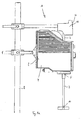
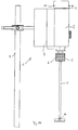
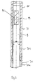
- FIGS. 1a to 1c 3 show three different embodiments of a laboratory stirrer 1 according to the invention, in particular an overhead stirrer, with an agitator 2 and a stirrer shaft 3.
- the agitator 2 is designed in such a way that the agitator shaft 3 can extend through the agitator 2.
- the stirring shaft 3 comprises a measuring sensor 10 and a measuring circuit 9 connected to the measuring sensor 10 (FIG. Figure 1c ), wherein the measuring sensor 10 and the measuring circuit 9 are each integrated in the stirring shaft 3.
- the measured data measured by the measuring sensor 10, in particular during the stirring of a medium are processed in the stirring shaft 3 and transmitted to a receiving unit 11 of the laboratory stirrer 1.
- the measured data, others on the measured data based data and / or other information can be displayed on a display unit, such as a display 22.
- the agitator 2 comprises a stirrer housing 4, in which a drive unit, not shown, is included, which comprises a motor.
- the drive unit drives a rotatable holder 5, which holds the stirring shaft 3.
- the holder 5 is preferably designed for exchangeable holding of the stirring shaft 3.
- the agitator 2 can be operated with different stirrer shafts 3.
- the holder 5 in FIG. 1b is a quick chuck 6, to allow a comfortable and easy replacement of the stirring shaft 3 without tools.
- the agitator shaft 3 can rotate at up to 2000 revolutions / min.
- the measuring sensor 10 is designed as a temperature sensor and the receiving unit 11 for temperature measurement.
- the temperatures of the respective medium can be between -30 ° C and about + 220 ° C.
- the receiving unit 11 can of course also be designed for the evaluation and processing of other physical quantities. The description based on a temperature measurement is not a limitation of the invention.
- the stirring shaft 3 comprises the measuring circuit 9 and the measuring sensor 10, which measures the temperature in a medium to be stirred.
- the measuring sensor 10 outputs its measuring data to the measuring circuit 9, which comprises a data transmission device 91 ( Fig. 2 ), wherein in the measuring circuit 9, the measured data is processed, processed, parallel / serial converted, digitized and / or modulated.
- the data processing device 91 which is preferably arranged in the upper end 35 of the stirring shaft 3, transmits the measuring data of the measuring sensor 10 to the receiving unit 11 without contact.
- the contactless data transmission has the advantage that the receiving unit 11 and agitator shaft 3 can move relative to one another without mutual interference.
- the receiving unit 11 does not rotate with the agitator shaft 3. Preferably, it is stationary. However, it can also be movable, for example also rotate.
- the receiving unit 11 serves not only to receive measured data from the stirring shaft 3, but also to supply the measuring circuit 9 of the stirring shaft 3 with energy. Furthermore, the receiving unit 11 may include a control unit 21 ( Fig. 4 ), which uses the measurement data of the measured variable of the medium measured by the measuring sensor 10 and transmitted to the receiving unit 11 for controlling the measured variable of the medium and / or other process parameters. For example, in the measurement of the viscosity of the medium, a metering device can be regulated by means of which, for example, a liquid is added to the medium to be stirred.
- Both the measured data and the output signal of the control unit 21 or further information such as, for example, the rotational speed or the like can be tapped via one or more interfaces on the laboratory stirrer 1, in particular on the stirrer 2, preferably on the receiving unit 11. Preferably, only one interface is available for tapping all of the data and signals of interest. A wireless transmission is also conceivable.
- the receiving unit 11 is formed as a separate module.
- the receiving unit 11 and the agitator 2 are attached to a tripod 8 and in their position, in particular their height, adjustable, so that the receiving unit 11 can be arranged relative to the agitator 2 as a function of the position and size of the agitator shaft 3.
- a simple adaptation to different stirred vessels and to touching liquid quantities and stirring wavelengths can be made.
- the separate receiving unit 11 has the advantage that already existing agitators 2 can be expanded by the receiving unit 11 and agitator shafts 3 with an integrated temperature sensor 10 can also be used in conventional agitators 2.
- FIG. 1b shows a receiving unit 11 which is placed on the agitator housing 4.
- the agitator 2 and the receiving unit 11 are integrated in a common housing.
- Figure 1c shows a built-in stirrer housing 4 receiving unit 11. This is a compact device is formed, which is designed for the temperature measurement during stirring by means of the stirring shaft.
- the desired value to which the control unit 21 adjusts is adjustable.
- the desired value is adjustable on the control unit 21 itself or on the receiving unit 11.
- appropriate switches or buttons for example, pressure dials
- a touch-sensitive screen touch screen
- the controls for setting the setpoint can be integrated in operating units of the laboratory stirrer, which may be the case, for example, with a touch-screen operation.
- the stirrer shaft 3 is shown in detail. It is designed as a hollow shaft and has for example an outer diameter of 8 to 10 mm and an inner diameter of 4 to 8 mm.
- the Agitator shaft 3 includes a first shaft portion 30a and a second (shorter) shaft portion 30b.
- the shaft portion 30a of the stirring shaft 3 is a stainless steel tube 31, at its lower end 32 (FIG. Fig. 2 ), a stirring element 33 is provided, wherein the lower end 32 faces away from the agitator 2 during stirring and is immersed in the medium to be stirred.
- the stirring element 33 can be exchangeably fixed to the stirring shaft 3, preferably it is integrated in the stirring shaft 3.
- the stirring member 33 may be formed as an agitating blade 34 and fixed by means of a hexagon or a nut to be selected depending on the medium to be stirred. Stirring elements 33 known from the prior art can thus be fastened to the stirrer shaft 3. It is also conceivable that the measuring sensor 10 is integrated in the stirring element 33. Stirring shaft 3 and stirring element 33 represent a stirring member of the laboratory stirrer.
- the shaft portion 30 b is arranged, which is preferably formed of a non-magnetic and in particular magnetically non-shielding shaft piece 36 which is connected to the stainless steel tube 31.
- the shaft piece 36 is preferably formed of glass, ceramic or synthetic resin.
- the stirring shaft 3 is suitable in this embodiment for energy and / or data transmission by means of a magnetic field.
- FIG. 3 It can be seen that the first shaft portion 30a has a groove and the second shaft portion 30b has a corresponding recess, so that the two shaft portions 30a, 30b can be rotationally fixed to each other according to the tongue and groove principle.
- the connection of the two sections 30a, 30b leaves no relative movement between them and is so tight that at least no liquid can enter.
- the measuring circuit 9 and the measuring sensor 10 are integrated inside the stirring shaft 3, the measuring circuit 9 and the measuring sensor 10 are integrated.
- the measuring circuit 9 is integrated on an axially extending board, at the end of the measuring sensor 10 is arranged.
- the sensor 10 need not be integrated in the board. It can also be formed as a separate component, which is connected by means of an electrical connection (cable) to the board.
- a conventional platinum sensor can be used, e.g. a PT 1000 sensor to extend the preferred temperature range.
- Measurement data of the temperature of the medium to be measured are transferred from the measuring sensor 10 to the measuring circuit 9.
- the measuring circuit 9 comprises the data transmission device 91, which transmits the measurement data of the measuring sensor 10 to the receiving unit 11 without contact, as shown in FIG FIG. 4 is shown.
- the measuring circuit 9 comprises a measuring electronics 92 ( Fig. 2 ) for digitizing the measurement signals and measurement data, a designed as a voltage regulator power supply 94, a microprocessor 95, a control circuit 96 and a modulator 97.
- the measuring electronics 92 may alternatively be integrated in the measuring sensor 10, for example in a temperature sensor.
- the control circuit 96 can, for example, start the microprocessor 95 as soon as a sufficient voltage supply of the measuring circuit 9 is provided by the power supply 94, as shown in the block diagram FIG. 5a can be seen.
- the receiving unit 11 comprises a power supply 12, a microprocessor 13, a generator 14, a power unit 15 and an amplifier 16.
- the block diagram of the receiving unit 11 is shown in FIG FIG. 5b shown.
- the receiving unit 11 also has a transformer 18 designed as a coil 17 in order to transmit energy and data to the stirring shaft 3 or to receive data from the stirring shaft 3.
- the coil 17 is preferably a cylindrical coil whose cylinder axis extends axially to the stirring shaft 3, so that the stirring shaft 3 rotates within the coil 17, wherein between the coil 17 and the shaft 3, a gap of at least 1 mm, preferably of at least 3 mm and more preferably at least 5 mm is formed.
- the stirring shaft 3 Since the stirring shaft 3 does not have its own energy source, it must be supplied with power by the receiving unit 11. Preferably, the transmission between the stirring shaft 3 and the receiving unit 11 takes place inductively or by means of a magnetic field.
- the stirring shaft 3 has a coil 99 at its upper end 35.
- the data transmission device 91 comprises the coil 99.
- the stirring shaft 3 therefore consists of non-magnetic material in the region of the coil 99, for example of the non-magnetic shaft 36.
- the coil 99 acts to transmit (electrical) energy and / or data with a magnetic field together, which is generated by a coupling device 19 of the receiving unit 11, in particular a magnetic field source.
- the magnetic field source 19 does not rotate with the stirring shaft 3.
- the magnetic field source 19 is integrated in the receiving unit 11, as in FIG FIG. 4 shown.
- the magnetic field source 19 is formed by the coil 17, the generator 14, the power section 15 and the amplifier 16.
- the magnetic field source is in FIG. 4 shown in dashed lines.
- the magnetic field source 19 and the agitator 2 are arranged in a common housing.
- the agitator housing 4 forms a common housing for the agitator 2 and the receiving unit 11, the receiving unit 11 comprising the magnetic field source 19.
- the agitator shaft 3 can be inserted into the rotating holder 5 far enough that its upper end 35 projects beyond the holder 5 in the axial direction and preferably extends into the agitator housing 4, particularly preferably into the receiving unit 11.
- the non-contact energy transfer to the stirring shaft 2 can be effected, for example, by moving the coil 99 of the stirring shaft 3 in a static magnetic field.
- the rotational movement of the stirring shaft 3 is carried out by means of the holder 5 of the agitator 2 driven by a drive unit.
- An energy transfer to the stirring shaft 3 preferably takes place inductively, magnetically, electromagnetically and / or with an alternating magnetic field.
- a permanent magnet could be rotated in the receiving unit 11, so that an alternating magnetic field is produced, wherein the permanent magnet and the agitator shaft 3 perform a relative movement.
- the magnetic field source 19 of the receiving unit 11 may include a coil for (electromagnetic) generation of a magnetic field.
- the coil is identical to the coil 17 of the receiving unit 11.
- the coil 17 is fed by an alternating current, which is generated by a supply current electronics 20 for generating an alternating magnetic field.
- the power supply electronics 20 may be formed, for example, from the generator 14 and the power unit 15.
- the alternating current fed into the coil 17 generates an alternating magnetic field which induces a voltage in the coil 99 of the stirring shaft 3.
- the energy transmission to the stirring shaft 3 could be effected optoelectronically, for example by means of LEDs.
- the transmission of the measured data, in particular the temperature data, from the stirring shaft 3 to the receiving unit 11 can also take place optoelectronically, for example by using light or by non-visible light sources, eg by means of LEDs.
- the data transmission device 91 of the agitator shaft 3 may preferably comprise a light transmitter, for example a semiconductor light transmitter. This light transmitter can preferably be arranged on the plug-in end face of the agitator shaft 3, ie on the end face at the upper end 35.
- the receiving unit 11 may comprise a light receiver, which is arranged opposite to the light transmitter of the stirring shaft 3 in such a way that an optical transmission between the light transmitter and the light receiver can take place.
- the data transmission between the stirring shaft 3 and the receiving unit 11 also takes place inductively, magnetically and / or electromagnetically.
- a magnetic field can be generated, which is received in the receiving unit 11, and whose signal is evaluated.
- an independent power supply in the stirring shaft 3 is necessary.
- the measuring circuit 9 of the stirring shaft 3 operates as a transponder, in particular as a so-called passive RFID transponder (Radio Frequency Identification transponder).
- the (electro) magnetic alternating field generated by the magnetic source 19 induces a voltage in the coil 99, so that the associated induction current supplies the measuring circuit 9 with energy.
- the microprocessor 95 of the measuring circuit 9 generates a useful signal which corresponds to the measured (digitized) measuring data of the temperature sensor 9. In this case, energy is consumed in the measuring circuit 9 as a function of the measured data, which energy is detected in the receiving unit 11.
- the change in power consumption can be done, for example, by shorting coil 99. Since the measuring circuit 9 does not have its own energy source, it does not itself generate a magnetic field in order to actively transmit measured values to the receiving unit 11.
- the measuring circuit 9 therefore comprises the modulator 97, which is controlled by the microprocessor 95.
- the modulator 97 is controlled as a function of the measured signals measured by the measuring sensor 10.
- the measurement data can be transmitted as a modulated signal to the receiving unit 11, for example, wherein the (digitized) measurement data as a useful signal are superimposed on the carrier signal generated by the receiving unit 11.
- the modulator 97 is determined how much energy is removed by the coil 99 of the magnetic field generated by the magnetic field source 19. For this purpose, a (useful) signal proportional to the (digitized) measured data is generated. This useful signal is superimposed on the unmodulated (carrier) signal of the alternating magnetic field of the magnetic field source 19. The amount of energy taken from the measuring circuit 9 and its change act on the magnetic field source 19 back. The reaction is registered by the receiving unit 11. It can decode the modulated measurement signal from the change in the alternating field caused by the removal of energy or the reaction to the magnetic field source 19 and deduce it from the modulated measured values.
- the measurement data can therefore be transmitted in particular by means of load modulation, i. if the coil 99 of the measuring circuit 9 acting as a transponder is located in the near field of the coil 17 of the receiving unit 11 acting as a reading device, the measuring circuit 9 withdraws the energy generated by the coil 17 energy field, causing a voltage change in the acting as a reading coil 17 coil, so that a modulation of the current flowing through the coil 99 and the impedance of the measuring circuit 9, the transmission of the measured data from the measuring circuit 9 to the receiving unit 11 is possible.
- load modulation i. if the coil 99 of the measuring circuit 9 acting as a transponder is located in the near field of the coil 17 of the receiving unit 11 acting as a reading device, the measuring circuit 9 withdraws the energy generated by the coil 17 energy field, causing a voltage change in the acting as a reading coil 17 coil, so that a modulation of the current flowing through the coil 99 and the impedance of the measuring circuit 9, the transmission of the measured data from the measuring circuit 9 to the receiving unit 11
- the use of an alternating electromagnetic field or an alternating magnetic field, but also the use of an RFID transponder have the advantage that a transmission of data and / or energy can also take place when the stirrer shaft 3 is stationary.
- the stirring shaft can therefore be at rest for its operation and, in particular, for the determination and transmission of the measured data. Of course she can also rotate.
- the position, position or rotational speed of the stirring shaft 3 has no influence on the measurement or transmission of the measured data to the receiving unit 11.
Landscapes
- Chemical & Material Sciences (AREA)
- Chemical Kinetics & Catalysis (AREA)
- Engineering & Computer Science (AREA)
- Computer Networks & Wireless Communication (AREA)
- Physics & Mathematics (AREA)
- General Physics & Mathematics (AREA)
- Mixers Of The Rotary Stirring Type (AREA)
- Accessories For Mixers (AREA)
Applications Claiming Priority (1)
| Application Number | Priority Date | Filing Date | Title |
|---|---|---|---|
| DE102008038833.5A DE102008038833B4 (de) | 2008-08-13 | 2008-08-13 | Laborrührer |
Publications (2)
| Publication Number | Publication Date |
|---|---|
| EP2153887A2 true EP2153887A2 (fr) | 2010-02-17 |
| EP2153887A3 EP2153887A3 (fr) | 2010-03-24 |
Family
ID=41327335
Family Applications (1)
| Application Number | Title | Priority Date | Filing Date |
|---|---|---|---|
| EP09008403A Withdrawn EP2153887A3 (fr) | 2008-08-13 | 2009-06-26 | Dispositif de malaxage avec transmission de données sans contact |
Country Status (3)
| Country | Link |
|---|---|
| US (1) | US20100039883A1 (fr) |
| EP (1) | EP2153887A3 (fr) |
| DE (1) | DE102008038833B4 (fr) |
Cited By (7)
| Publication number | Priority date | Publication date | Assignee | Title |
|---|---|---|---|---|
| EP2714257B1 (fr) | 2011-05-27 | 2015-09-02 | IKA - Werke GmbH & Co. KG | Agitateur doté d'un mécanisme d'agitation et d'un moteur d'entraînement |
| WO2015169827A3 (fr) * | 2014-05-06 | 2016-01-07 | List Holding Ag | Dispositif et procédé de mise en oeuvre de processus mécaniques, chimiques et/ou thermiques |
| DE102014009984A1 (de) | 2014-07-04 | 2016-01-07 | Ulrich Spranger | Verfahren und Vorrichtung zur Reinigung der Innenflächen von Rundbehältern |
| WO2017001051A1 (fr) * | 2015-07-01 | 2017-01-05 | Ika - Werke Gmbh & Co. Kg | Dispositif de dispersion |
| WO2017144218A1 (fr) * | 2016-02-26 | 2017-08-31 | Sartorius Stedim Biotech Gmbh | Agitateur comprenant un capteur, en particulier pour un bioréacteur |
| EP3319496A4 (fr) * | 2015-07-08 | 2019-03-27 | Breville Pty Limited | Appareil de cuisine pour la détection de propriétés d'aliments et de boissons |
| WO2020249766A1 (fr) * | 2019-06-14 | 2020-12-17 | Fraunhofer-Gesellschaft zur Förderung der angewandten Forschung e.V. | Agitateur, système d'agitation et procédé pour la mesure sans fil et/ou sans batterie de paramètres de processus |
Families Citing this family (7)
| Publication number | Priority date | Publication date | Assignee | Title |
|---|---|---|---|---|
| DE102011076730A1 (de) * | 2011-05-30 | 2012-12-06 | Endress + Hauser Conducta Gesellschaft für Mess- und Regeltechnik mbH + Co. KG | Messanordnung zur Bestimmung einer physikalischen oder chemischen Prozessgröße eines Mediums |
| DE202013012366U1 (de) * | 2013-06-18 | 2016-06-27 | Ika-Werke Gmbh & Co. Kg | Magnetrührer mit SAW-Sensor |
| DE102015008482A1 (de) * | 2015-07-01 | 2017-02-16 | Ika-Werke Gmbh & Co. Kg | Dispergierwerkzeug, Dispergiervorrichtung und Dispergieranordnung |
| EP3203647A1 (fr) * | 2016-02-08 | 2017-08-09 | Siemens Aktiengesellschaft | Transmission de donnees et mise a disposition d'energie electrique |
| DE202017100926U1 (de) * | 2017-02-20 | 2018-05-24 | Hans Heidolph GmbH | Rührvorrichtung |
| US11039715B2 (en) * | 2017-07-05 | 2021-06-22 | Illinois Tool Works Inc. | Food processing machine adaptive to food load |
| CN108828166A (zh) * | 2018-06-30 | 2018-11-16 | 关岭自治县断桥绿华农产品农民专业合作社 | 多功能的食品安全的检测测量装置 |
Family Cites Families (11)
| Publication number | Priority date | Publication date | Assignee | Title |
|---|---|---|---|---|
| FR2035173B1 (fr) * | 1969-03-22 | 1974-06-21 | Polska Akademia Nauk Instytut | |
| US4704035A (en) * | 1986-10-06 | 1987-11-03 | Baker Perkins, Inc. | Remotely transmitting batch mixer |
| US4962495A (en) * | 1988-10-03 | 1990-10-09 | Lucas Aerospace Power Transmission Corp. | Apparatus and method for transmitting condition data from a rotating member to a stationary device |
| EP0454952A1 (fr) * | 1990-05-02 | 1991-11-06 | Mettler-Toledo AG | Mesures de températures dans des appareils de rhéologie |
| EP0589093A1 (fr) * | 1992-09-22 | 1994-03-30 | Sigma-Delta N.V. | Robot de cuisine à outil mélangeur intelligent |
| CA2161224C (fr) * | 1994-02-25 | 1999-02-02 | Gerald Brinker | Appareil pour mesurer la dissolution |
| DE19843689A1 (de) * | 1998-09-24 | 2000-03-30 | Basf Ag | Verfahren zur Parametermessung in Reaktoren mit beweglichen Rührern |
| US20040050836A1 (en) * | 2000-09-29 | 2004-03-18 | Nesbitt Geoffrey John | Assembly of an integrated vessel transporter and at least one reaction vessel and integrated vessel transporter for transporting a chemical substance |
| GB0311959D0 (en) * | 2003-05-23 | 2003-06-25 | Glaxo Group Ltd | Energy delivery system |
| EP1830684A2 (fr) * | 2004-09-10 | 2007-09-12 | Soup O'Matic B.V. | Appareil avec couvercle flotteur pour servir des liquides commestibles chauds |
| EP1776998B1 (fr) * | 2005-10-21 | 2008-07-23 | Abb Research Ltd. | Mélangeur |
-
2008
- 2008-08-13 DE DE102008038833.5A patent/DE102008038833B4/de not_active Revoked
-
2009
- 2009-06-26 EP EP09008403A patent/EP2153887A3/fr not_active Withdrawn
- 2009-08-13 US US12/540,415 patent/US20100039883A1/en not_active Abandoned
Cited By (13)
| Publication number | Priority date | Publication date | Assignee | Title |
|---|---|---|---|---|
| EP2714257B2 (fr) † | 2011-05-27 | 2018-09-05 | IKA - Werke GmbH & Co. KG | Agitateur doté d'un mécanisme d'agitation et d'un moteur d'entraînement |
| EP2714257B1 (fr) | 2011-05-27 | 2015-09-02 | IKA - Werke GmbH & Co. KG | Agitateur doté d'un mécanisme d'agitation et d'un moteur d'entraînement |
| WO2015169827A3 (fr) * | 2014-05-06 | 2016-01-07 | List Holding Ag | Dispositif et procédé de mise en oeuvre de processus mécaniques, chimiques et/ou thermiques |
| DE102014009984A1 (de) | 2014-07-04 | 2016-01-07 | Ulrich Spranger | Verfahren und Vorrichtung zur Reinigung der Innenflächen von Rundbehältern |
| WO2017001051A1 (fr) * | 2015-07-01 | 2017-01-05 | Ika - Werke Gmbh & Co. Kg | Dispositif de dispersion |
| CN107810051A (zh) * | 2015-07-01 | 2018-03-16 | 艾卡工厂有限及两合公司 | 弥散装置 |
| US10486123B2 (en) | 2015-07-01 | 2019-11-26 | Ika-Werke Gmbh & Co. Kg | Dispersing device |
| CN107810051B (zh) * | 2015-07-01 | 2021-08-31 | 艾卡工厂有限及两合公司 | 弥散装置 |
| EP3319496A4 (fr) * | 2015-07-08 | 2019-03-27 | Breville Pty Limited | Appareil de cuisine pour la détection de propriétés d'aliments et de boissons |
| AU2016290887B2 (en) * | 2015-07-08 | 2021-06-10 | Breville Pty Limited | Kitchen appliance for sensing food and beverage properties |
| US11213170B2 (en) | 2015-07-08 | 2022-01-04 | Breville Pty Limited | Kitchen appliance for sensing food and beverage properties |
| WO2017144218A1 (fr) * | 2016-02-26 | 2017-08-31 | Sartorius Stedim Biotech Gmbh | Agitateur comprenant un capteur, en particulier pour un bioréacteur |
| WO2020249766A1 (fr) * | 2019-06-14 | 2020-12-17 | Fraunhofer-Gesellschaft zur Förderung der angewandten Forschung e.V. | Agitateur, système d'agitation et procédé pour la mesure sans fil et/ou sans batterie de paramètres de processus |
Also Published As
| Publication number | Publication date |
|---|---|
| EP2153887A3 (fr) | 2010-03-24 |
| DE102008038833B4 (de) | 2014-02-27 |
| DE102008038833A1 (de) | 2010-02-25 |
| US20100039883A1 (en) | 2010-02-18 |
Similar Documents
| Publication | Publication Date | Title |
|---|---|---|
| DE102008038833B4 (de) | Laborrührer | |
| EP2571547B1 (fr) | Système de traitement médical | |
| DE112018005502T5 (de) | Temperaturmessvorrichtung und Temperaturmessverfahren für zu behandelnde Substanz sowie Rühr-/Entgasungsverfahren | |
| EP2913431A2 (fr) | Système de détection de la consommation d'un fluide dans une installation de nettoyage ou de lavage | |
| DE69127476T2 (de) | Messfühler zur Messung der Eigenschaften von Fluiden | |
| WO2010015496A1 (fr) | Dispositif de mélange avec chauffage par induction | |
| DE60219906T2 (de) | Rührvorrichtung und verfahren zur messung eines parameters einer zu rührenden substanz | |
| EP3560592B2 (fr) | Centrifuge de laboratoire, récipient centrifuge pour une centrifuge de laboratoire et procédé de fonctionnement d'un récipient centrifuge | |
| EP0476668A1 (fr) | Méthode et dispositif de conditionnement et de deshydratation subséquente des boues | |
| DE102016103456B4 (de) | Rührwerk mit Sensor, insbesondere für einen Bioreaktor | |
| EP1743227A1 (fr) | Appareil de terrain electrique pour l'automatisation de processus | |
| DE102005041500A1 (de) | Vakuumpumpe | |
| DE102004052156B4 (de) | Vorrichtung zum Schütteln von Medien | |
| DE4440250B4 (de) | Meßwerterfassungsvorrichtung | |
| EP3317005B1 (fr) | Dispositif de dispersion | |
| WO2010020413A1 (fr) | Dispositif de balayage inductif des traits de graduation d'une minuterie mécanique à rouleaux, sur des compteurs de tout type | |
| DE102011076730A1 (de) | Messanordnung zur Bestimmung einer physikalischen oder chemischen Prozessgröße eines Mediums | |
| EP0548490B1 (fr) | Régulation électronique de la vitesse de rotation pour appareils de laboratoire, notamment mélangeur magnétique | |
| DE102013220469A1 (de) | System, Zentrifugationseinheit, Zentrifuge und Verfahren zur induktiven Stromerzeugung | |
| DE202025100946U1 (de) | Vorrichtung zum Schleifen oder Polieren von Werkstücken mit einem Behälter zur Aufnahme eines Schleif- oder Poliermediums | |
| EP4077630A1 (fr) | Bioréacteur, plaque d'extrémité pour un bioréacteur et unité de communication de données pour une plaque d'extrémité | |
| DE102013200350A1 (de) | Mikrofluidische Analysekartusche und Auswerteeinheit | |
| Bornemann-Pfeiffer | Design and validation of an integrated NMR micro mixer | |
| DE102008038046A1 (de) | Rheologische Einrichtung | |
| DE202025001326U1 (de) | Vorrichtung für rotationsbasierte Analyseverfahren |
Legal Events
| Date | Code | Title | Description |
|---|---|---|---|
| PUAI | Public reference made under article 153(3) epc to a published international application that has entered the european phase |
Free format text: ORIGINAL CODE: 0009012 |
|
| AK | Designated contracting states |
Kind code of ref document: A2 Designated state(s): AT BE BG CH CY CZ DE DK EE ES FI FR GB GR HR HU IE IS IT LI LT LU LV MC MK MT NL NO PL PT RO SE SI SK TR |
|
| AX | Request for extension of the european patent |
Extension state: AL BA RS |
|
| PUAL | Search report despatched |
Free format text: ORIGINAL CODE: 0009013 |
|
| AK | Designated contracting states |
Kind code of ref document: A3 Designated state(s): AT BE BG CH CY CZ DE DK EE ES FI FR GB GR HR HU IE IS IT LI LT LU LV MC MK MT NL NO PL PT RO SE SI SK TR |
|
| AX | Request for extension of the european patent |
Extension state: AL BA RS |
|
| STAA | Information on the status of an ep patent application or granted ep patent |
Free format text: STATUS: THE APPLICATION IS DEEMED TO BE WITHDRAWN |
|
| 18D | Application deemed to be withdrawn |
Effective date: 20100925 |