EP2154097B1 - Courroie d'élévateur pour un élévateur et procédé de fabrication d'une telle courroie d'élévateur - Google Patents
Courroie d'élévateur pour un élévateur et procédé de fabrication d'une telle courroie d'élévateur Download PDFInfo
- Publication number
- EP2154097B1 EP2154097B1 EP09175749A EP09175749A EP2154097B1 EP 2154097 B1 EP2154097 B1 EP 2154097B1 EP 09175749 A EP09175749 A EP 09175749A EP 09175749 A EP09175749 A EP 09175749A EP 2154097 B1 EP2154097 B1 EP 2154097B1
- Authority
- EP
- European Patent Office
- Prior art keywords
- belt
- drive wheel
- tensile
- part belt
- lift
- Prior art date
- Legal status (The legal status is an assumption and is not a legal conclusion. Google has not performed a legal analysis and makes no representation as to the accuracy of the status listed.)
- Not-in-force
Links
- 238000004519 manufacturing process Methods 0.000 title claims description 12
- 238000000034 method Methods 0.000 title description 3
- 239000000463 material Substances 0.000 claims description 54
- 238000009434 installation Methods 0.000 claims description 12
- 229920001971 elastomer Polymers 0.000 claims description 11
- 239000000806 elastomer Substances 0.000 claims description 11
- 229910000831 Steel Inorganic materials 0.000 claims description 10
- 239000010959 steel Substances 0.000 claims description 10
- 239000004952 Polyamide Substances 0.000 claims description 8
- 239000000969 carrier Substances 0.000 claims description 8
- 229920002647 polyamide Polymers 0.000 claims description 8
- 239000011248 coating agent Substances 0.000 claims description 7
- 238000000576 coating method Methods 0.000 claims description 7
- 238000001125 extrusion Methods 0.000 claims description 6
- 229920001169 thermoplastic Polymers 0.000 claims description 6
- 229920002943 EPDM rubber Polymers 0.000 claims description 5
- 239000004814 polyurethane Substances 0.000 claims description 5
- 239000004698 Polyethylene Substances 0.000 claims description 4
- 230000007935 neutral effect Effects 0.000 claims description 4
- 229920000573 polyethylene Polymers 0.000 claims description 4
- 229920001084 poly(chloroprene) Polymers 0.000 claims description 3
- 239000004744 fabric Substances 0.000 claims description 2
- 239000004417 polycarbonate Substances 0.000 claims description 2
- 229920000515 polycarbonate Polymers 0.000 claims description 2
- -1 polyethylene Polymers 0.000 claims description 2
- 239000004800 polyvinyl chloride Substances 0.000 claims description 2
- 238000007373 indentation Methods 0.000 claims 1
- 239000012815 thermoplastic material Substances 0.000 description 6
- 230000000694 effects Effects 0.000 description 4
- 239000000835 fiber Substances 0.000 description 4
- 239000004416 thermosoftening plastic Substances 0.000 description 4
- 238000005299 abrasion Methods 0.000 description 3
- 230000005540 biological transmission Effects 0.000 description 3
- 230000000295 complement effect Effects 0.000 description 3
- 229920002635 polyurethane Polymers 0.000 description 3
- 230000035939 shock Effects 0.000 description 3
- 240000006829 Ficus sundaica Species 0.000 description 2
- 239000000853 adhesive Substances 0.000 description 2
- 230000001070 adhesive effect Effects 0.000 description 2
- 238000013016 damping Methods 0.000 description 2
- 239000000203 mixture Substances 0.000 description 2
- 229920003023 plastic Polymers 0.000 description 2
- 239000004033 plastic Substances 0.000 description 2
- OKTJSMMVPCPJKN-UHFFFAOYSA-N Carbon Chemical compound [C] OKTJSMMVPCPJKN-UHFFFAOYSA-N 0.000 description 1
- 238000010521 absorption reaction Methods 0.000 description 1
- 239000000654 additive Substances 0.000 description 1
- 238000004026 adhesive bonding Methods 0.000 description 1
- 238000005452 bending Methods 0.000 description 1
- 229910052799 carbon Inorganic materials 0.000 description 1
- 239000004917 carbon fiber Substances 0.000 description 1
- 238000005520 cutting process Methods 0.000 description 1
- 230000003247 decreasing effect Effects 0.000 description 1
- 230000001419 dependent effect Effects 0.000 description 1
- 239000003365 glass fiber Substances 0.000 description 1
- 238000003780 insertion Methods 0.000 description 1
- 230000037431 insertion Effects 0.000 description 1
- 230000007774 longterm Effects 0.000 description 1
- 239000011159 matrix material Substances 0.000 description 1
- 230000002787 reinforcement Effects 0.000 description 1
- 239000012209 synthetic fiber Substances 0.000 description 1
- 229920002994 synthetic fiber Polymers 0.000 description 1
- 238000007669 thermal treatment Methods 0.000 description 1
Images
Classifications
-
- B—PERFORMING OPERATIONS; TRANSPORTING
- B66—HOISTING; LIFTING; HAULING
- B66B—ELEVATORS; ESCALATORS OR MOVING WALKWAYS
- B66B7/00—Other common features of elevators
- B66B7/06—Arrangements of ropes or cables
-
- B—PERFORMING OPERATIONS; TRANSPORTING
- B66—HOISTING; LIFTING; HAULING
- B66B—ELEVATORS; ESCALATORS OR MOVING WALKWAYS
- B66B7/00—Other common features of elevators
- B66B7/06—Arrangements of ropes or cables
- B66B7/062—Belts
-
- B—PERFORMING OPERATIONS; TRANSPORTING
- B29—WORKING OF PLASTICS; WORKING OF SUBSTANCES IN A PLASTIC STATE IN GENERAL
- B29D—PRODUCING PARTICULAR ARTICLES FROM PLASTICS OR FROM SUBSTANCES IN A PLASTIC STATE
- B29D29/00—Producing belts or bands
- B29D29/10—Driving belts having wedge-shaped cross-section
-
- B—PERFORMING OPERATIONS; TRANSPORTING
- B66—HOISTING; LIFTING; HAULING
- B66B—ELEVATORS; ESCALATORS OR MOVING WALKWAYS
- B66B7/00—Other common features of elevators
-
- F—MECHANICAL ENGINEERING; LIGHTING; HEATING; WEAPONS; BLASTING
- F16—ENGINEERING ELEMENTS AND UNITS; GENERAL MEASURES FOR PRODUCING AND MAINTAINING EFFECTIVE FUNCTIONING OF MACHINES OR INSTALLATIONS; THERMAL INSULATION IN GENERAL
- F16G—BELTS, CABLES, OR ROPES, PREDOMINANTLY USED FOR DRIVING PURPOSES; CHAINS; FITTINGS PREDOMINANTLY USED THEREFOR
- F16G1/00—Driving-belts
- F16G1/28—Driving-belts with a contact surface of special shape, e.g. toothed
-
- D—TEXTILES; PAPER
- D07—ROPES; CABLES OTHER THAN ELECTRIC
- D07B—ROPES OR CABLES IN GENERAL
- D07B1/00—Constructional features of ropes or cables
- D07B1/22—Flat or flat-sided ropes; Sets of ropes consisting of a series of parallel ropes
-
- D—TEXTILES; PAPER
- D07—ROPES; CABLES OTHER THAN ELECTRIC
- D07B—ROPES OR CABLES IN GENERAL
- D07B2201/00—Ropes or cables
- D07B2201/20—Rope or cable components
- D07B2201/2083—Jackets or coverings
- D07B2201/2087—Jackets or coverings being of the coated type
-
- D—TEXTILES; PAPER
- D07—ROPES; CABLES OTHER THAN ELECTRIC
- D07B—ROPES OR CABLES IN GENERAL
- D07B2501/00—Application field
- D07B2501/20—Application field related to ropes or cables
- D07B2501/2007—Elevators
Definitions
- the present invention relates to a belt for an elevator installation, to a manufacturing method for such a belt and to an elevator installation with such a belt.
- An elevator installation comprises an elevator cage and, as a rule, a counterweight, which are movable in an elevator shaft or along free-standing guide devices.
- the elevator installation has at least one drive unit with at least one traction sheave each, which carries the elevator car and the counterweight via one or more belts and / or transmits the required drive forces thereto.
- the elevator car and the counterweight can be connected via the same belt, which are guided over the traction sheave (s) and act both as a support means and as a drive means.
- the elevator car and the counterweight can also be carried on separate straps and driven by separate drive belt.
- a belt according to the present invention can be used for any of the functions described above, that is, as a combined drive and carrying belt, as a carrying strap, which runs over at least one deflection wheel (carrying roller) and connects the elevator car with the counterweight and carries both, or as a drive belt , which has only drive function and at least one traction sheave.
- Such belts for elevator installations usually comprise a belt body made of an elastomer.
- tension members in the form of steel and / or plastic cords are embedded in the belt body.
- the cords may be formed, for example, as strands or ropes made of steel wires or plastic fibers. They are advantageously arranged in the neutral fiber of the belt cross-section, in which no tensile or compressive stresses occur when looping around a belt pulley.
- the belt on a drive wheel facing the traction side has a rib arrangement with a plurality of extending in the longitudinal direction of the belt wedge-shaped ribs which engage in corresponding grooves on the drive wheel.
- the output shaft of the drive unit itself may be designed as a drive wheel.
- the tensile carriers are embedded in a matrix of a soft elastomer, in particular polyurethane (PU), polychloroprene (CR) or ethylene-propylene-diene rubber (EPDM).
- PU polyurethane
- CR polychloroprene
- EPDM ethylene-propylene-diene rubber
- Such belts can not or only partially be used in safety-sensitive devices such as an elevator system, since the risk of a belt break due to the damage described above is too high. Likewise, such straps can not be used to transmit high forces as this increases the risk of such damage.
- An object of the present invention is therefore to provide an elevator system in which the risk of failure due to a belt breakage is reduced. Another object of the present invention is to provide a belt for such an elevator system, which can also transmit higher forces. Another object of the present invention is to provide a method of manufacturing such a belt.
- a belt according to the features of claim 1 a manufacturing method according to the features of claim 11 and an elevator installation according to the features of claim 14 are provided.
- a belt for an elevator system comprises a first part belt of a first material in which a tension member assembly having at least one tensile member of steel wire or steel wire strands or steel wire ropes is arranged, and a second part belt of a second, of the first material different material.
- the first material comprises at least one thermoplastic.
- This thermoplastic material is preferably polyamide (PA), polyethylene (PE), polycarbonate (PC) or polyvinyl chloride (PVC).
- the first material may also comprise a blend of two or more thermoplastics, a so-called polyblend.
- the first material may also contain additives, in particular fibers such as carbon or glass fibers.
- the first material may comprise a web of thermoplastic.
- the second material of the second sub-belt with regard to its function, in particular the frictional contact with a drive wheel, the damping of vibrations and shocks and / or the elasticity required for wrapping belt pulleys.
- the forces to be transmitted by the tension members and thus the permissible belt load can be increased, since the surface pressures and stresses generated by the tension members in the belt are first absorbed by the first part belt whose first material can be suitably selected with regard to the present stress , In the first sub-belt distributed by the tension members on the belt body loads distributed so that on the second belt at the connecting surface to the first belt acting maximum surface pressures and compressive stresses occur only reduced.
- the first partial belt is made relatively thin, so that it does not significantly affect the bending elasticity of the belt despite its higher hardness.
- the thickness of the first part belt is at most 60%, preferably at most 40% and particularly preferably at most 30% of the total thickness of the belt.
- the tension members do not cut or only slightly under high load. They also endure the compressive and / or shear stresses that occur, without showing inadmissibly high deformations, abrasion or disruption.
- the coefficient of friction of the first material which also forms the belt back facing away from the traction surface, is relatively small.
- the friction force occurring between the deflecting wheels and the belt which is to be overcome for laterally guiding the belt on the deflecting wheel, is reduced during the wrapping of deflecting wheels without longitudinal grooves.
- the harmful lateral frictional load of the belt - for example, by incidentssbordusionn the deflecting wheels - and thus reduces the required drive power of the elevator system and increases the life of the belt.
- a belt according to the present invention for this purpose, a coating of the belt back of a material having a lower coefficient of friction and / or a higher abrasion resistance than the first material.
- the Switzerland choiran extract comprises at least one, but preferably a plurality of substantially parallel tension members, which may be arranged in particular in the longitudinal direction of the belt.
- the inventive arrangement of the tension members in the stable first part belt facilitates their positionally correct arrangement during the manufacturing process, since the tension members are already fixed in the first material when the second material is applied.
- the tension members may be formed as a single wire or, preferably, constructed of strands or ropes, the strands or ropes being made of steel wires.
- the tension members of the tension member arrangement are arranged in or in the vicinity of the neutral fiber of the entire belt in which no tensile or compressive stresses occur during the deflection around a pulley, in particular a drive wheel.
- the second belt part of the belt for cooperation with a drive wheel of the elevator system is provided.
- it has for this purpose a traction surface, in which at least one V-rib is formed, which engages in a corresponding, substantially complementary groove in the running surface of the drive wheel.
- a plurality of V-ribs may preferably be formed next to each other. These do not necessarily have to be connected with each other.
- Separate, arranged on the first sub-belt V-ribs of the second sub-belt can compensate for positional deviations of the individual grooves of a drive wheel to each other advantageous.
- an at least thin connecting web which extends between adjacent ribs on the connecting surface to the first part belt, advantageously increases this connecting surface and thus the strength of the connection between the first and the second part belt.
- a V-rib has a substantially trapezoidal cross-section with a flank angle of 60 ° to 120 ° measured between its two flanks.
- flank angle 60 ° to 120 ° measured between its two flanks.
- Other cross-sectional shapes such as triangular cross-sections, possible.
- the traction surface of the belt has a coating which has a defined coefficient of friction with the running surface of a drive wheel of the elevator installation.
- This coefficient of friction may be higher than that of the second material, for example, to improve traction. Alternatively, it may be lower than that of the second material. This reduces on the one hand the wear on the traction surface and can eliminate the risk of jamming of the V-ribs in the grooves of a pulley, especially in a traction surface on which one or more V-ribs are formed.
- the second material for the second part belt preferably comprises an elastomer, in particular polyurethane, polychloroprene or ethylene-propylene-diene rubber or a mixture of two or more elastomers.
- an elastomeric second sub-belt is sufficiently flexible for wrapping pulleys with small diameters. At the same time dampens such a second material in a known manner advantageous vibrations and shocks in the belt. At the same time it bears when interacting with a running surface of a drive wheel occurring for the transmission of tensile forces in the belt shear deformation due to its elastic properties.
- a relatively soft second material can be selected, whose hardness at room temperature is advantageously less than 95 Shore (A), preferably less than 90 Shore (A) and particularly preferably less than 85 Shore (A), since according to the invention high local surface pressures of the individual tensile carriers are absorbed by the first, harder material and transferred to the second material as a more homogeneous and lower surface pressure via the connecting surface.
- a belt according to an embodiment of the present invention is preferably manufactured in the following steps.
- First, the first partial belt is made of the first material. This is advantageously done by extruding the thermoplastic material, which allows a uniform, inexpensive and endless production.
- the tension members can be arranged in the first part belt, for which purpose the individual tension members are fed to the resulting first part belt during the extrusion process so that they are completely enveloped by the first material at least on the side facing the second part belt ,
- the tension members are completely enveloped by the first material.
- the side of the tension member facing the second partial belt is separated therefrom by the first material.
- first the first partial belt can be produced and then the individual tensile carriers can be arranged on the side facing away from the connecting surface to the second partial belt.
- the first part of belt on this side facing away advantageous grooves for the correct position positioning of the tension members.
- the fixation of the tension members in the grooves of the first belt can be done by means of thermal treatment of the thermoplastic material or by adding an adhesive.
- the tension members which are arranged in the region of the second belt side facing away from the first belt, but can also be fixed to the second belt by a third sub-belt connected to said side of the first belt part, for example by gluing and / or extrusion is that the tension members are fixed between the first and third sub-belt.
- the second sub-belt is made of the second material and firmly connected to the first sub-belt. This can preferably be done by extruding the second onto the first partial belt. In this case, advantageously, the V-ribs of the traction surface of the second sub-belt can be formed.
- the second belt can also be bonded to the first belt part.
- the second material for this purpose contains an adhesive which, when extruded onto the first sub-belt by thermal bonding, creates a firm connection thereto.
- the advantageous coating of the traction surface of the second sub-belt can be applied during its manufacture or subsequently.
- a synthetic fiber fabric, a layer of another elastomer, a flocking layer and / or a thermoplastic layer containing, for example, polyamide can be arranged on the surface of its traction surface during the extrusion of the second part belt, wherein the coating advantageously bonds firmly to the still mouldable second material ,
- An elevator installation comprises an elevator car, a drive unit with at least one drive wheel and a belt arrangement with at least one belt according to an embodiment of the present invention.
- the belt assembly may also comprise a plurality of belts according to one or more embodiments of the present invention, which may be fixedly or detachably connected to each other, for example by positive engagement. This makes it possible to assemble a relatively wide belt assembly of several narrow, easier-to-use straps on site.
- the drive wheel or wheels have a V-rib profile that is substantially complementary to the traction surface of the second belt.
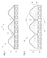
- Fig. 1 shows a cross section through a belt 12 according to an embodiment of the present invention.
- This comprises a first part belt 13 made of a thermoplastic material, polyamide in the embodiment.
- the first part belt 13 is produced by extrusion, being fed to it in its manufacture tension members 14 of multi-stranded steel wires such that they are completely enclosed and fixed in the finished first part belt 13.
- tension members 14 of multi-stranded steel wires such that they are completely enclosed and fixed in the finished first part belt 13.
- a second sub-belt 15 from a Elastomer, polyurethane in the exemplary embodiment, extruded onto the first partial belt 13.
- the side facing away from the first belt part of the second belt Part 15 is formed as a traction surface, which for cooperation with a drive wheel 4.1 (s. Fig.
- V-ribbed profile on its tread.
- the traction surface of the second sub-belt 15 on V-ribs 15.1 the flanks of which enclose an angle ⁇ of 90 °.
- the V-ribs 15.1 are connected to each other by relatively thin connecting webs 16 extending between adjacent ribs on the connecting surface between the two sub-belts, whereby the strength of the connection between the two sub-belt is increased.
- the traction surface is provided with a thin coating of polyamide to lower the coefficient of friction. Due to the V-ribs 15.1 still gives sufficient traction, wherein the polyamide coating advantageously reduces the wear of the traction surface and reduces the risk of jamming of the belt 12 in the drive wheel 4.1.
- first and second partial belts and the tension members are in Fig. 1 to illustrate the individual elements not shown to scale. Rather, the first partial belt 13 is actually thinner than the second partial belt 15 and has a thickness which is just sufficient to completely enclose the tension members 14 and to transmit the tension introduced by them as homogeneously as possible to the second partial belt.
- the existing from the thicker, but more elastic second part of belt 15 and the less elastic, but thinner first part belt 13 existing belt 12 is sufficiently elastic to the pulleys 4.1, 4.2 and 4.3 (s. Fig. 2 ) to smoothly entwine.
- Fig. 2 shows a cross section through a belt 22 according to another embodiment of the present invention.
- This also comprises a first part belt 23 made of a thermoplastic material and a second part belt 25 made of an elastomer, which is extruded onto the first part belt 13 and forms a traction surface with a plurality of V-ribs 25.1.
- the V-ribs between their trapezoidal or wedge-shaped contact sections 28 and the first sub-belt 23 have a substantially rectangular base section 29 which comprises at least 20% of the height of the entire second sub-belt 25.
- the V-ribs 25.1, ie their base portions 29 are completely separated from each other by gaps 26.
- Such an embodiment has the advantage that the trapezoidal or wedge-shaped contact portions 28 of the V-ribs 25.1 are elastically displaceable relative to each other transversely to the longitudinal direction of the belt 22, so that the V-rib arrangement can adapt to a total elastic to the existing V-groove profile of a corresponding pulley, in which the The shape and / or the mutual distances of the V-ribs within permitted limits of the shape or the intervals of the V-ribs of the belt differ.
- This embodiment has advantages in terms of traction between a drive wheel and the belt, on the life of the belt and the pulleys and on the noise of the entire belt drive.
- Fig. 2 an embodiment of the belt 22 is shown, in which the tension members 14 are inserted into grooves 27 of the first belt part 23, as already described above.
- the grooves 27 have been thermally deformed in the illustrated embodiment after the insertion of the tension members 14, that the tension members are stably fixed in the first sub-belt.
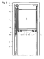
- Fig. 3 schematically shows a section through an installed in an elevator shaft 1 elevator system with the belt 12.
- the elevator system comprises a fixed in an elevator shaft 1 drive unit 2 with a drive wheel 4.1, guided on car guide rails 5 elevator car 3 with mounted below the cabin floor 6 guide wheels in the form of Cabin roller rollers 4.2, a counterweight guided on counterweight guide rails 7 8 with another guide wheel in the form of a counterweight roller 4.3, and the belt 12 for the elevator car 3 and the counterweight 8, which transmits the driving force from the drive wheel 4.1 of the drive unit 2 to the elevator car and the counterweight ,
- the belt 12 is attached at one of its ends below the drive wheel 4.1 to a first belt fixing point 10. From this, it extends down to the counterweight carrying roller 4.3, wraps around this and extends from this to the drive wheel 4.1, wraps around it and runs along the gegenimportants districten cabin wall down, wraps on both sides of the elevator car depending mounted below the elevator car 3 cabin roll 4.2 at 90 ° each and extends along the side facing away from the counterweight 8 cabin wall up to a second belt fixing point eleventh
- the plane of the drive wheel 4.1 can be arranged at right angles to the counterweight-side cabin wall and its vertical projection can be outside the vertical projection of the elevator car 3. It is therefore preferable that the drive wheel 4.1 has a small diameter, so that the distance between the left-side cabin wall and the opposite wall of the elevator shaft 1 can be as small as possible. In addition, a small drive wheel diameter allows the use of a gearless drive motor with relatively low drive torque as the drive unit. 2
- the drive wheel 4.1 and the counterweight support roller 4.3 are provided at their periphery with grooves which are formed substantially complementary to the ribs 15.1 of the belt 12.
- the ribs present on its traction surface lie in corresponding grooves of the pulley, thereby ensuring excellent belt guidance on these pulleys.
- the traction capability is improved by the between the grooves of the pulley serving as a pulley 4.1 and the ribs of the belt 12 wedge effect.
- the sliding surface of the belt 12 and the Kabinentragrollen 4.2 corresponding V-ribs.
- a third sub-belt made of polyurethane which has like the second sub-belt V-ribs.
Landscapes
- Engineering & Computer Science (AREA)
- General Engineering & Computer Science (AREA)
- Mechanical Engineering (AREA)
- Lift-Guide Devices, And Elevator Ropes And Cables (AREA)
- Belt Conveyors (AREA)
Claims (14)
- Courroie (12 ; 22) pour une installation d'ascenseur, qui comprend :- une première partie de courroie (13) composée d'un premier matériau ; étant précisé que le premier matériau est constitué par une matière thermoplastique ou contient une matière thermoplastique et qu'il contient du polyamide (PA), du polyéthylène (PE), du polycarbonate (PC) ou du poly(chorure de vinyle) (PVC) ;- un dispositif à support de traction avec au moins un support de traction (14) qui est disposé dans la première partie de courroie ; étant précisé que le support de traction (14) se compose d'un fil d'acier simple ou d'un toron de fils d'acier ou d'un câble de fils d'acier ; et- une seconde partie de courroie (15 ; 25) composée d'un second matériau, étant précisé que le second matériau comprend un élastomère et qu'il comprend du polyuréthanne (PU) et/ou du polychloroprène (CR) et/ou du caoutchouc éthylène-propylène-diène (EPDM) ;étant précisé que les supports de traction prévus dans la courroie finie sont disposés dans la fibre neutre de toute la courroie.
- Courroie (12 ; 22) selon la revendication 1, étant précisé que le premier matériau est choisi dans l'un des groupes de matériaux suivants :- mélange polymère qui contient l'un des matériaux cités,- ou tissu composé de l'un des matériaux cités.
- Courroie (12 ; 22) selon la revendication 1 ou 2, étant précisé que le premier matériau présente à température ambiante une résistance à la traction minimale selon DIN 53455 ou ISO 527 de 45 N/mm2.
- Courroie (12 ; 22) selon l'une des revendications précédentes, étant précisé que le premier matériau présente à température ambiante un allongement à la rupture minimal selon DIN 53455 ou ISO 527 de 45%.
- Courroie (12 ; 22) selon l'une des revendications précédentes, étant précisé que le premier matériau présente à température ambiante une dureté à la bille minimale selon DIN 53456 ou ISO 2039 (H358/30s) de 30 N/mm2, de préférence de 50N/mm2, plus spécialement de 70 N/mm2.
- Courroie (12 ; 22) selon l'une des revendications précédentes, étant précisé que l'épaisseur de la première partie de courroie (13 ; 23) représente au maximum 60%, de préférence au maximum 40% et plus spécialement au maximum 30% de l'épaisseur totale de la courroie.
- Courroie (12 ; 22) selon l'une des revendications précédentes, étant précisé que la seconde partie de courroie (15 ; 25) présente une surface de traction, pour la coopération avec une poulie motrice de l'installation d'ascenseur, dans laquelle est formée au moins une nervure cunéiforme (15.1 ; 25.1).
- Courroie (12 ; 22) selon l'une des revendications précédentes, étant précisé que la surface de traction de la seconde partie de courroie (15) destinée à coopérer avec une poulie motrice (4.1) de l'installation d'ascenseur présente un revêtement qui présente par rapport à la surface de roulement de la poulie motrice (4.1) un coefficient de friction défini, en particulier un coefficient de friction plus élevé ou plus faible que le second matériau.
- Courroie (12 ; 22) selon l'une des revendications précédentes, étant précisé que le second matériau présente à température ambiante une dureté de moins de 95 Shore(A), de préférence de moins de 90 Shore(A) et plus spécialement une dureté de moins de 85 Shore(A).
- Courroie (22) selon l'une des revendications précédentes, étant précisé- qu'au moins deux nervures cunéiformes (25.1) présentent chacune une partie de contact trapézoïdale ou cunéiforme (28) et une partie formant socle (29) globalement rectangulaire,- les parties formant socles rectangulaires (29) sont disposées entre les parties de contact (28) et la première partie de courroie (23) et comprennent au moins 20% de la hauteur de la seconde partie de courroie (25),- et les parties formant socles (29) sont complètement séparées les unes des autres par des intervalles (26).
- Procédé de fabrication pour une courroie (12 ; 22) selon l'une des revendications 1 à 10, avec les étapes qui consistent :à fabriquer une première partie de courroie (13) avec les supports de traction (14) disposés dans celle-ci, à partir d'un premier matériau selon la revendication 1, étant précisé que la fabrication se fait en particulier par extrusion ;à fabriquer une seconde partie de courroie (15) à partir d'un second matériau selon la revendication 1 ; età relier les première et seconde parties de courroie ; étant précisé que les supports de traction prévus dans la première partie de courroie sont placés de telle sorte qu'ils soient disposés dans la fibre neutre de toute la courroie.
- Procédé de fabrication selon la revendication 11, étant précisé que la seconde partie de courroie est extrudée sur la première partie de courroie et/ou est collée thermiquement à celle-ci.
- Procédé de fabrication selon la revendication 11 ou 12, étant précisé que le premier matériau est choisi, pour ses caractéristiques et son épaisseur de recouvrement sur les supports de traction, de telle sorte qu'il reçoit des pressions superficielles locales des supports de traction et qu'il les transmette au second matériau sous forme de pression superficielle plus homogène et plus faible, par l'intermédiaire d'une surface de liaison.
- Installation d'ascenseur avec une cabine d'ascenseur (3), une unité d'entraînement (2) avec une poulie motrice (4.1) et un dispositif à courroie avec au moins une courroie (12 ; 22) selon l'une des revendications 1 à 10.
Priority Applications (1)
| Application Number | Priority Date | Filing Date | Title |
|---|---|---|---|
| EP09175749A EP2154097B1 (fr) | 2006-08-11 | 2007-08-08 | Courroie d'élévateur pour un élévateur et procédé de fabrication d'une telle courroie d'élévateur |
Applications Claiming Priority (3)
| Application Number | Priority Date | Filing Date | Title |
|---|---|---|---|
| EP06118819 | 2006-08-11 | ||
| EP07113974A EP1886796B1 (fr) | 2006-08-11 | 2007-08-08 | Courroie sans fin pour une installation d'élévation et installation d'élévation dotée d'une telle courroie sans fin |
| EP09175749A EP2154097B1 (fr) | 2006-08-11 | 2007-08-08 | Courroie d'élévateur pour un élévateur et procédé de fabrication d'une telle courroie d'élévateur |
Related Parent Applications (2)
| Application Number | Title | Priority Date | Filing Date |
|---|---|---|---|
| EP07113974.5 Division | 2007-08-08 | ||
| EP07113974A Division EP1886796B1 (fr) | 2006-08-11 | 2007-08-08 | Courroie sans fin pour une installation d'élévation et installation d'élévation dotée d'une telle courroie sans fin |
Publications (2)
| Publication Number | Publication Date |
|---|---|
| EP2154097A1 EP2154097A1 (fr) | 2010-02-17 |
| EP2154097B1 true EP2154097B1 (fr) | 2011-09-28 |
Family
ID=37714449
Family Applications (2)
| Application Number | Title | Priority Date | Filing Date |
|---|---|---|---|
| EP07113974A Not-in-force EP1886796B1 (fr) | 2006-08-11 | 2007-08-08 | Courroie sans fin pour une installation d'élévation et installation d'élévation dotée d'une telle courroie sans fin |
| EP09175749A Not-in-force EP2154097B1 (fr) | 2006-08-11 | 2007-08-08 | Courroie d'élévateur pour un élévateur et procédé de fabrication d'une telle courroie d'élévateur |
Family Applications Before (1)
| Application Number | Title | Priority Date | Filing Date |
|---|---|---|---|
| EP07113974A Not-in-force EP1886796B1 (fr) | 2006-08-11 | 2007-08-08 | Courroie sans fin pour une installation d'élévation et installation d'élévation dotée d'une telle courroie sans fin |
Country Status (19)
| Country | Link |
|---|---|
| EP (2) | EP1886796B1 (fr) |
| JP (1) | JP2008069008A (fr) |
| KR (1) | KR20080014705A (fr) |
| CN (1) | CN101122097B (fr) |
| AR (1) | AR062349A1 (fr) |
| AT (2) | ATE526272T1 (fr) |
| AU (1) | AU2007205738A1 (fr) |
| BR (1) | BRPI0703706A2 (fr) |
| CA (1) | CA2596716A1 (fr) |
| DE (1) | DE502007002382D1 (fr) |
| DK (1) | DK1886796T3 (fr) |
| ES (2) | ES2339885T3 (fr) |
| MX (1) | MX2007009685A (fr) |
| NO (1) | NO20074120L (fr) |
| PL (1) | PL1886796T3 (fr) |
| PT (1) | PT1886796E (fr) |
| RU (1) | RU2448032C2 (fr) |
| TW (1) | TW200829504A (fr) |
| ZA (1) | ZA200706598B (fr) |
Cited By (1)
| Publication number | Priority date | Publication date | Assignee | Title |
|---|---|---|---|---|
| US11214465B2 (en) | 2016-12-16 | 2022-01-04 | Otis Elevator Company | Elevator system suspension member |
Families Citing this family (21)
| Publication number | Priority date | Publication date | Assignee | Title |
|---|---|---|---|---|
| RU2500849C2 (ru) | 2008-08-15 | 2013-12-10 | Отис Элевэйтор Компани | Подъемная система и способ ее изготовления |
| WO2010072690A1 (fr) * | 2008-12-22 | 2010-07-01 | Inventio Ag | Moyen porteur d'ascenseur, procédé de fabrication d'un tel moyen porteur et installation d'ascenseur dotée d'un tel moyen porteur d'ascenseur |
| CN101875467B (zh) * | 2010-03-29 | 2012-05-23 | 江南嘉捷电梯股份有限公司 | 一种电梯用牵引带 |
| ES2682205T3 (es) | 2010-05-13 | 2018-09-19 | Otis Elevator Company | Método de fabricación de una tela tejida que tiene una separación deseada entre miembros de tensión |
| RU2533960C1 (ru) * | 2010-09-20 | 2014-11-27 | Отис Элевэйтор Компани | Узел для подвешивания и/или привода подъемника, имеющий по меньшей мере одну поверхность, обеспечивающую тягу или образование сил сцепления, содержащую размещенные открыто волокна переплетения |
| CN102002872B (zh) * | 2010-10-28 | 2013-06-05 | 西子电梯集团有限公司 | 升降机用纤维编织挠性复合牵引带及制作方法 |
| CN103328368B (zh) * | 2011-01-21 | 2016-09-28 | 奥的斯电梯公司 | 用于减少带的噪声的系统和方法 |
| CN102304863B (zh) * | 2011-08-02 | 2014-01-15 | 宁波谷达机电有限公司 | 电梯曳引带及其制造方法 |
| CN102359543A (zh) * | 2011-10-20 | 2012-02-22 | 无锡通用钢绳有限公司 | 电梯用扁平钢带 |
| FI123534B (fi) * | 2012-02-13 | 2013-06-28 | Kone Corp | Nostolaitteen köysi, hissi ja menetelmä köyden valmistamiseksi |
| EP2799217B1 (fr) * | 2013-04-30 | 2015-06-03 | Kone Corporation | Procédé de fabrication d'une corde, corde et élévateur |
| US9873593B2 (en) | 2015-05-07 | 2018-01-23 | Otis Elevator Company | Fire resistant coated steel belt |
| WO2017155943A1 (fr) | 2016-03-09 | 2017-09-14 | Otis Elevator Company | Courroie d'ascenseur en tissu renforcé avec une résistance à l'usure interne améliorée |
| DE102016209633A1 (de) * | 2016-06-02 | 2017-12-07 | Contitech Antriebssysteme Gmbh | Keilriemen und Verfahren zu seiner Herstellung |
| US10941021B2 (en) * | 2017-08-28 | 2021-03-09 | Otis Elevator Company | Sheave for belt with profile tracking features |
| EP3697714B1 (fr) | 2017-10-17 | 2022-06-15 | Inventio AG | Installation d'ascenseur dotée de poulies de détour avec différentes géométries de rainure |
| DE102018202454A1 (de) * | 2018-02-19 | 2019-08-22 | Contitech Antriebssysteme Gmbh | Riementrieb sowie Zug- oder Tragriemen dafür |
| US10882719B2 (en) * | 2018-03-29 | 2021-01-05 | Thyssenkrupp Elevator Ag | Composite elevator belt |
| CN109132789A (zh) * | 2018-10-30 | 2019-01-04 | 艾艾精密工业输送系统(上海)股份有限公司 | 一种复合电梯曳引带 |
| DE102019207434A1 (de) * | 2019-05-21 | 2020-11-26 | Contitech Antriebssysteme Gmbh | Zahnriemen |
| DE102019217625A1 (de) * | 2019-11-15 | 2021-05-20 | Contitech Antriebssysteme Gmbh | Aufzugsgurt mit Corden aus beschichteten Litzen |
Family Cites Families (23)
| Publication number | Priority date | Publication date | Assignee | Title |
|---|---|---|---|---|
| DE1141443B (de) * | 1957-05-29 | 1962-12-20 | Dayco Corp | Verfahren zur Herstellung von Mehrfachkeilriemen |
| US3948113A (en) * | 1974-11-29 | 1976-04-06 | The Goodyear Tire & Rubber Company | Multi-ribbed power transmission belt and method of making said belt |
| US4177688A (en) * | 1978-02-08 | 1979-12-11 | Dayco Corporation | Endless power transmission belt and method for making same |
| DE2905362A1 (de) * | 1979-02-13 | 1980-08-14 | Dayco Corp | Verfahren zur herstellung lagenfoermiger riemen |
| JPS5667348A (en) * | 1979-11-08 | 1981-06-06 | Mitsuboshi Belting Ltd | Rubber composition |
| DE3527640C2 (de) * | 1985-08-01 | 1997-08-14 | Norddeutsche Seekabelwerk Gmbh | Vorrichtung und Verfahren zur Herstellung von Riemen aus plastifizierbarem Werkstoff |
| JPS62199553U (fr) * | 1986-06-09 | 1987-12-18 | ||
| DE4316917A1 (de) | 1993-05-20 | 1994-11-24 | Gates Rubber Co | Keilriemen oder Keilrippenriemen |
| DE19851761B4 (de) * | 1998-11-10 | 2014-10-09 | Arntz Beteiligungs Gmbh & Co. Kg | Antriebsriemen |
| JP2000304103A (ja) * | 1999-04-21 | 2000-11-02 | Bando Chem Ind Ltd | Vリブドベルト |
| CA2313421A1 (fr) * | 1999-08-26 | 2001-02-26 | The Goodyear Tire & Rubber Company | Courroie de transmission d'energie |
| FI117433B (fi) * | 2000-12-08 | 2006-10-13 | Kone Corp | Hissi ja hissin vetopyörä |
| US6488123B2 (en) * | 2001-02-12 | 2002-12-03 | Otis Elevator Company | Directional uniformity of flat tension members for elevators |
| CA2449385A1 (fr) * | 2001-06-21 | 2003-01-03 | Habasit Ag | Courroie monolithique comprenant des copolymeres ethylene-.alpha. olefine |
| US6609990B2 (en) * | 2001-07-18 | 2003-08-26 | The Gates Corporation | Power transmission belt and method |
| JP2005509578A (ja) * | 2001-11-23 | 2005-04-14 | インベンテイオ・アクテイエンゲゼルシヤフト | ベルト状動力伝達手段、特に支持および/または駆動手段としてのくさび形リブ付きベルトを有するエレベータ |
| US20030121729A1 (en) * | 2002-01-02 | 2003-07-03 | Guenther Heinz | Lift belt and system |
| JP3921603B2 (ja) * | 2002-01-18 | 2007-05-30 | ニッタ株式会社 | エレベータ駆動用ベルト |
| EP1555233B1 (fr) * | 2002-10-25 | 2018-06-06 | Mitsubishi Denki Kabushiki Kaisha | Cordage pour ascenseur |
| US7037578B2 (en) | 2002-12-11 | 2006-05-02 | The Goodyear Tire & Rubber Company | Power transmission belt |
| DK1555234T3 (da) * | 2004-01-06 | 2006-08-21 | Inventio Ag | Elevator |
| DE102004030722A1 (de) * | 2004-06-25 | 2006-01-19 | Contitech Antriebssysteme Gmbh | Mit Festigkeitsträgern versehener Flachriemen für Aufzugsanlagen |
| DE102005062353A1 (de) * | 2005-05-10 | 2007-05-16 | Sks Sitzkomponenten Gmbh & Co | Mehrschichtiges Werkstoffteil und daraus hergestelltes Formteil, insbesondere zur Herstellung von Möbeln |
-
2007
- 2007-08-01 CN CN2007101383877A patent/CN101122097B/zh not_active Expired - Fee Related
- 2007-08-01 JP JP2007200354A patent/JP2008069008A/ja not_active Withdrawn
- 2007-08-06 TW TW096128832A patent/TW200829504A/zh unknown
- 2007-08-08 DE DE502007002382T patent/DE502007002382D1/de active Active
- 2007-08-08 EP EP07113974A patent/EP1886796B1/fr not_active Not-in-force
- 2007-08-08 PL PL07113974T patent/PL1886796T3/pl unknown
- 2007-08-08 ES ES07113974T patent/ES2339885T3/es active Active
- 2007-08-08 ES ES09175749T patent/ES2374695T3/es active Active
- 2007-08-08 ZA ZA200706598A patent/ZA200706598B/xx unknown
- 2007-08-08 AT AT09175749T patent/ATE526272T1/de active
- 2007-08-08 EP EP09175749A patent/EP2154097B1/fr not_active Not-in-force
- 2007-08-08 AT AT07113974T patent/ATE452745T1/de active
- 2007-08-08 DK DK07113974.5T patent/DK1886796T3/da active
- 2007-08-08 PT PT07113974T patent/PT1886796E/pt unknown
- 2007-08-09 NO NO20074120A patent/NO20074120L/no not_active Application Discontinuation
- 2007-08-09 CA CA002596716A patent/CA2596716A1/fr not_active Abandoned
- 2007-08-10 RU RU2007130681/11A patent/RU2448032C2/ru not_active IP Right Cessation
- 2007-08-10 MX MX2007009685A patent/MX2007009685A/es not_active Application Discontinuation
- 2007-08-10 AU AU2007205738A patent/AU2007205738A1/en not_active Abandoned
- 2007-08-10 AR ARP070103575A patent/AR062349A1/es unknown
- 2007-08-10 KR KR1020070080871A patent/KR20080014705A/ko not_active Withdrawn
- 2007-08-10 BR BRPI0703706-6A patent/BRPI0703706A2/pt not_active IP Right Cessation
Cited By (1)
| Publication number | Priority date | Publication date | Assignee | Title |
|---|---|---|---|---|
| US11214465B2 (en) | 2016-12-16 | 2022-01-04 | Otis Elevator Company | Elevator system suspension member |
Also Published As
| Publication number | Publication date |
|---|---|
| ES2339885T3 (es) | 2010-05-26 |
| RU2448032C2 (ru) | 2012-04-20 |
| EP1886796A1 (fr) | 2008-02-13 |
| PL1886796T3 (pl) | 2010-06-30 |
| CN101122097B (zh) | 2011-11-16 |
| EP2154097A1 (fr) | 2010-02-17 |
| ZA200706598B (en) | 2008-09-25 |
| CA2596716A1 (fr) | 2008-02-11 |
| PT1886796E (pt) | 2010-03-29 |
| TW200829504A (en) | 2008-07-16 |
| ATE526272T1 (de) | 2011-10-15 |
| ES2374695T3 (es) | 2012-02-21 |
| EP1886796B1 (fr) | 2009-12-23 |
| AU2007205738A1 (en) | 2008-02-28 |
| BRPI0703706A2 (pt) | 2009-04-07 |
| AR062349A1 (es) | 2008-11-05 |
| NO20074120L (no) | 2008-02-12 |
| KR20080014705A (ko) | 2008-02-14 |
| DE502007002382D1 (de) | 2010-02-04 |
| ATE452745T1 (de) | 2010-01-15 |
| MX2007009685A (es) | 2009-02-18 |
| RU2007130681A (ru) | 2009-02-20 |
| DK1886796T3 (da) | 2010-05-03 |
| JP2008069008A (ja) | 2008-03-27 |
| CN101122097A (zh) | 2008-02-13 |
Similar Documents
| Publication | Publication Date | Title |
|---|---|---|
| EP2154097B1 (fr) | Courroie d'élévateur pour un élévateur et procédé de fabrication d'une telle courroie d'élévateur | |
| EP1886961B1 (fr) | Courroie d'élévateur pour un élévateur et procédé de fabrication d'une telle courroie d'élévateur | |
| EP1886960B1 (fr) | Installation d'élévation dotée d'un moyen de support d'élévation | |
| EP2305591B1 (fr) | Courroie d'élévateur pour un élévateur et procédé de fabrication d'une telle courroie d'élévateur | |
| EP2141110B1 (fr) | Moyen de support d'élévation pour un système d'élévation, système d'élévation doté d'un tel moyen d'élévation et procédé de montage d'un tel système d'élévation | |
| EP2125593B1 (fr) | Courroie d'entraînement, procédé de fabrication d'une telle courroie d'entraînement et installation d'ascenseur dotée d'une telle courroie | |
| EP2488436B1 (fr) | Installation d'ascenseur et moyen de support pour une telle installation | |
| EP2285554B1 (fr) | Procédé et dispositif de fabrication d'un moyen de support en forme de courroie pour installation d'ascenseur, moyen de support en forme de courroie et installation d'ascenseur dotée d'un tel moyen de support | |
| EP2146919B1 (fr) | Moyen de traction | |
| EP1724226B1 (fr) | Ascenseur | |
| EP2346770B1 (fr) | Système de traction pour un ascenseur | |
| EP1446348A1 (fr) | Ascenseur pourvu d'un moyen de transmission du type courroie, en particulier d'une courroie trapezoidale a nervures, servant de moyen de support et/ou de moyen d'entrainement | |
| DE102008037536A1 (de) | Zugmittel, Zugmitteltrieb mit diesem Zugmittel und Aufzugsanlage | |
| EP1886797B1 (fr) | Courroie d'élévateur pour un élévateur et procédé de fabrication d'une telle courroie d'élévateur | |
| DE102008037541A1 (de) | Zugmittel | |
| EP1886795B1 (fr) | Courroie sans fin pour un élévateur et procédé de fabrication d'une telle courroie sans fin | |
| EP1728915B1 (fr) | Elément porteur avec une liaison de forme pour coupler plusieurs câbles |
Legal Events
| Date | Code | Title | Description |
|---|---|---|---|
| PUAI | Public reference made under article 153(3) epc to a published international application that has entered the european phase |
Free format text: ORIGINAL CODE: 0009012 |
|
| AC | Divisional application: reference to earlier application |
Ref document number: 1886796 Country of ref document: EP Kind code of ref document: P |
|
| AK | Designated contracting states |
Kind code of ref document: A1 Designated state(s): AT BE BG CH CY CZ DE DK EE ES FI FR GB GR HU IE IS IT LI LT LU LV MC MT NL PL PT RO SE SI SK TR |
|
| 17P | Request for examination filed |
Effective date: 20100816 |
|
| 17Q | First examination report despatched |
Effective date: 20100920 |
|
| GRAP | Despatch of communication of intention to grant a patent |
Free format text: ORIGINAL CODE: EPIDOSNIGR1 |
|
| RIC1 | Information provided on ipc code assigned before grant |
Ipc: B29D 29/10 20060101ALI20110323BHEP Ipc: F16G 5/06 20060101ALI20110323BHEP Ipc: F16G 5/14 20060101ALI20110323BHEP Ipc: D07B 1/22 20060101ALI20110323BHEP Ipc: B66B 7/06 20060101AFI20110323BHEP |
|
| GRAS | Grant fee paid |
Free format text: ORIGINAL CODE: EPIDOSNIGR3 |
|
| GRAA | (expected) grant |
Free format text: ORIGINAL CODE: 0009210 |
|
| AC | Divisional application: reference to earlier application |
Ref document number: 1886796 Country of ref document: EP Kind code of ref document: P |
|
| AK | Designated contracting states |
Kind code of ref document: B1 Designated state(s): AT BE BG CH CY CZ DE DK EE ES FI FR GB GR HU IE IS IT LI LT LU LV MC MT NL PL PT RO SE SI SK TR |
|
| REG | Reference to a national code |
Ref country code: GB Ref legal event code: FG4D Free format text: NOT ENGLISH |
|
| REG | Reference to a national code |
Ref country code: CH Ref legal event code: EP |
|
| REG | Reference to a national code |
Ref country code: IE Ref legal event code: FG4D |
|
| REG | Reference to a national code |
Ref country code: DE Ref legal event code: R096 Ref document number: 502007008274 Country of ref document: DE Effective date: 20111124 |
|
| REG | Reference to a national code |
Ref country code: NL Ref legal event code: VDEP Effective date: 20110928 |
|
| PG25 | Lapsed in a contracting state [announced via postgrant information from national office to epo] |
Ref country code: LT Free format text: LAPSE BECAUSE OF FAILURE TO SUBMIT A TRANSLATION OF THE DESCRIPTION OR TO PAY THE FEE WITHIN THE PRESCRIBED TIME-LIMIT Effective date: 20110928 Ref country code: FI Free format text: LAPSE BECAUSE OF FAILURE TO SUBMIT A TRANSLATION OF THE DESCRIPTION OR TO PAY THE FEE WITHIN THE PRESCRIBED TIME-LIMIT Effective date: 20110928 Ref country code: SE Free format text: LAPSE BECAUSE OF FAILURE TO SUBMIT A TRANSLATION OF THE DESCRIPTION OR TO PAY THE FEE WITHIN THE PRESCRIBED TIME-LIMIT Effective date: 20110928 |
|
| REG | Reference to a national code |
Ref country code: ES Ref legal event code: FG2A Ref document number: 2374695 Country of ref document: ES Kind code of ref document: T3 Effective date: 20120221 |
|
| LTIE | Lt: invalidation of european patent or patent extension |
Effective date: 20110928 |
|
| PG25 | Lapsed in a contracting state [announced via postgrant information from national office to epo] |
Ref country code: CY Free format text: LAPSE BECAUSE OF FAILURE TO SUBMIT A TRANSLATION OF THE DESCRIPTION OR TO PAY THE FEE WITHIN THE PRESCRIBED TIME-LIMIT Effective date: 20110928 Ref country code: LV Free format text: LAPSE BECAUSE OF FAILURE TO SUBMIT A TRANSLATION OF THE DESCRIPTION OR TO PAY THE FEE WITHIN THE PRESCRIBED TIME-LIMIT Effective date: 20110928 Ref country code: GR Free format text: LAPSE BECAUSE OF FAILURE TO SUBMIT A TRANSLATION OF THE DESCRIPTION OR TO PAY THE FEE WITHIN THE PRESCRIBED TIME-LIMIT Effective date: 20111229 Ref country code: SI Free format text: LAPSE BECAUSE OF FAILURE TO SUBMIT A TRANSLATION OF THE DESCRIPTION OR TO PAY THE FEE WITHIN THE PRESCRIBED TIME-LIMIT Effective date: 20110928 |
|
| REG | Reference to a national code |
Ref country code: IE Ref legal event code: FD4D |
|
| PG25 | Lapsed in a contracting state [announced via postgrant information from national office to epo] |
Ref country code: IS Free format text: LAPSE BECAUSE OF FAILURE TO SUBMIT A TRANSLATION OF THE DESCRIPTION OR TO PAY THE FEE WITHIN THE PRESCRIBED TIME-LIMIT Effective date: 20120128 Ref country code: CZ Free format text: LAPSE BECAUSE OF FAILURE TO SUBMIT A TRANSLATION OF THE DESCRIPTION OR TO PAY THE FEE WITHIN THE PRESCRIBED TIME-LIMIT Effective date: 20110928 Ref country code: SK Free format text: LAPSE BECAUSE OF FAILURE TO SUBMIT A TRANSLATION OF THE DESCRIPTION OR TO PAY THE FEE WITHIN THE PRESCRIBED TIME-LIMIT Effective date: 20110928 |
|
| PG25 | Lapsed in a contracting state [announced via postgrant information from national office to epo] |
Ref country code: RO Free format text: LAPSE BECAUSE OF FAILURE TO SUBMIT A TRANSLATION OF THE DESCRIPTION OR TO PAY THE FEE WITHIN THE PRESCRIBED TIME-LIMIT Effective date: 20110928 Ref country code: NL Free format text: LAPSE BECAUSE OF FAILURE TO SUBMIT A TRANSLATION OF THE DESCRIPTION OR TO PAY THE FEE WITHIN THE PRESCRIBED TIME-LIMIT Effective date: 20110928 Ref country code: PT Free format text: LAPSE BECAUSE OF FAILURE TO SUBMIT A TRANSLATION OF THE DESCRIPTION OR TO PAY THE FEE WITHIN THE PRESCRIBED TIME-LIMIT Effective date: 20120130 Ref country code: EE Free format text: LAPSE BECAUSE OF FAILURE TO SUBMIT A TRANSLATION OF THE DESCRIPTION OR TO PAY THE FEE WITHIN THE PRESCRIBED TIME-LIMIT Effective date: 20110928 |
|
| PG25 | Lapsed in a contracting state [announced via postgrant information from national office to epo] |
Ref country code: IE Free format text: LAPSE BECAUSE OF FAILURE TO SUBMIT A TRANSLATION OF THE DESCRIPTION OR TO PAY THE FEE WITHIN THE PRESCRIBED TIME-LIMIT Effective date: 20110928 Ref country code: DK Free format text: LAPSE BECAUSE OF FAILURE TO SUBMIT A TRANSLATION OF THE DESCRIPTION OR TO PAY THE FEE WITHIN THE PRESCRIBED TIME-LIMIT Effective date: 20110928 |
|
| PLBE | No opposition filed within time limit |
Free format text: ORIGINAL CODE: 0009261 |
|
| STAA | Information on the status of an ep patent application or granted ep patent |
Free format text: STATUS: NO OPPOSITION FILED WITHIN TIME LIMIT |
|
| PG25 | Lapsed in a contracting state [announced via postgrant information from national office to epo] |
Ref country code: PL Free format text: LAPSE BECAUSE OF FAILURE TO SUBMIT A TRANSLATION OF THE DESCRIPTION OR TO PAY THE FEE WITHIN THE PRESCRIBED TIME-LIMIT Effective date: 20110928 |
|
| 26N | No opposition filed |
Effective date: 20120629 |
|
| REG | Reference to a national code |
Ref country code: DE Ref legal event code: R097 Ref document number: 502007008274 Country of ref document: DE Effective date: 20120629 |
|
| BERE | Be: lapsed |
Owner name: INVENTIO A.G. Effective date: 20120831 |
|
| REG | Reference to a national code |
Ref country code: CH Ref legal event code: PL |
|
| PG25 | Lapsed in a contracting state [announced via postgrant information from national office to epo] |
Ref country code: MC Free format text: LAPSE BECAUSE OF NON-PAYMENT OF DUE FEES Effective date: 20120831 |
|
| PG25 | Lapsed in a contracting state [announced via postgrant information from national office to epo] |
Ref country code: CH Free format text: LAPSE BECAUSE OF NON-PAYMENT OF DUE FEES Effective date: 20120831 Ref country code: LI Free format text: LAPSE BECAUSE OF NON-PAYMENT OF DUE FEES Effective date: 20120831 |
|
| PG25 | Lapsed in a contracting state [announced via postgrant information from national office to epo] |
Ref country code: BE Free format text: LAPSE BECAUSE OF NON-PAYMENT OF DUE FEES Effective date: 20120831 |
|
| PG25 | Lapsed in a contracting state [announced via postgrant information from national office to epo] |
Ref country code: BG Free format text: LAPSE BECAUSE OF FAILURE TO SUBMIT A TRANSLATION OF THE DESCRIPTION OR TO PAY THE FEE WITHIN THE PRESCRIBED TIME-LIMIT Effective date: 20111228 |
|
| REG | Reference to a national code |
Ref country code: AT Ref legal event code: MM01 Ref document number: 526272 Country of ref document: AT Kind code of ref document: T Effective date: 20120831 |
|
| PG25 | Lapsed in a contracting state [announced via postgrant information from national office to epo] |
Ref country code: AT Free format text: LAPSE BECAUSE OF NON-PAYMENT OF DUE FEES Effective date: 20120831 |
|
| PG25 | Lapsed in a contracting state [announced via postgrant information from national office to epo] |
Ref country code: MT Free format text: LAPSE BECAUSE OF FAILURE TO SUBMIT A TRANSLATION OF THE DESCRIPTION OR TO PAY THE FEE WITHIN THE PRESCRIBED TIME-LIMIT Effective date: 20110928 |
|
| PG25 | Lapsed in a contracting state [announced via postgrant information from national office to epo] |
Ref country code: TR Free format text: LAPSE BECAUSE OF FAILURE TO SUBMIT A TRANSLATION OF THE DESCRIPTION OR TO PAY THE FEE WITHIN THE PRESCRIBED TIME-LIMIT Effective date: 20110928 |
|
| PG25 | Lapsed in a contracting state [announced via postgrant information from national office to epo] |
Ref country code: LU Free format text: LAPSE BECAUSE OF NON-PAYMENT OF DUE FEES Effective date: 20120808 |
|
| PG25 | Lapsed in a contracting state [announced via postgrant information from national office to epo] |
Ref country code: HU Free format text: LAPSE BECAUSE OF FAILURE TO SUBMIT A TRANSLATION OF THE DESCRIPTION OR TO PAY THE FEE WITHIN THE PRESCRIBED TIME-LIMIT Effective date: 20070808 |
|
| REG | Reference to a national code |
Ref country code: FR Ref legal event code: PLFP Year of fee payment: 10 |
|
| REG | Reference to a national code |
Ref country code: FR Ref legal event code: PLFP Year of fee payment: 11 |
|
| REG | Reference to a national code |
Ref country code: FR Ref legal event code: PLFP Year of fee payment: 12 |
|
| PGFP | Annual fee paid to national office [announced via postgrant information from national office to epo] |
Ref country code: ES Payment date: 20190924 Year of fee payment: 13 Ref country code: FR Payment date: 20190822 Year of fee payment: 13 Ref country code: IT Payment date: 20190829 Year of fee payment: 13 |
|
| PGFP | Annual fee paid to national office [announced via postgrant information from national office to epo] |
Ref country code: GB Payment date: 20190821 Year of fee payment: 13 |
|
| GBPC | Gb: european patent ceased through non-payment of renewal fee |
Effective date: 20200808 |
|
| PG25 | Lapsed in a contracting state [announced via postgrant information from national office to epo] |
Ref country code: IT Free format text: LAPSE BECAUSE OF NON-PAYMENT OF DUE FEES Effective date: 20200808 Ref country code: FR Free format text: LAPSE BECAUSE OF NON-PAYMENT OF DUE FEES Effective date: 20200831 |
|
| PG25 | Lapsed in a contracting state [announced via postgrant information from national office to epo] |
Ref country code: GB Free format text: LAPSE BECAUSE OF NON-PAYMENT OF DUE FEES Effective date: 20200808 |
|
| PGFP | Annual fee paid to national office [announced via postgrant information from national office to epo] |
Ref country code: DE Payment date: 20210827 Year of fee payment: 15 |
|
| REG | Reference to a national code |
Ref country code: ES Ref legal event code: FD2A Effective date: 20220110 |
|
| PG25 | Lapsed in a contracting state [announced via postgrant information from national office to epo] |
Ref country code: ES Free format text: LAPSE BECAUSE OF NON-PAYMENT OF DUE FEES Effective date: 20200809 |
|
| REG | Reference to a national code |
Ref country code: DE Ref legal event code: R119 Ref document number: 502007008274 Country of ref document: DE |
|
| PG25 | Lapsed in a contracting state [announced via postgrant information from national office to epo] |
Ref country code: DE Free format text: LAPSE BECAUSE OF NON-PAYMENT OF DUE FEES Effective date: 20230301 |