EP2154113A2 - Dispositif pour le traitement chimique de condensats à partir d'une chaudière domestique - Google Patents
Dispositif pour le traitement chimique de condensats à partir d'une chaudière domestique Download PDFInfo
- Publication number
- EP2154113A2 EP2154113A2 EP09251987A EP09251987A EP2154113A2 EP 2154113 A2 EP2154113 A2 EP 2154113A2 EP 09251987 A EP09251987 A EP 09251987A EP 09251987 A EP09251987 A EP 09251987A EP 2154113 A2 EP2154113 A2 EP 2154113A2
- Authority
- EP
- European Patent Office
- Prior art keywords
- condensate
- housing
- hollow member
- cartridge
- inlet
- Prior art date
- Legal status (The legal status is an assumption and is not a legal conclusion. Google has not performed a legal analysis and makes no representation as to the accuracy of the status listed.)
- Withdrawn
Links
Images
Classifications
-
- C—CHEMISTRY; METALLURGY
- C02—TREATMENT OF WATER, WASTE WATER, SEWAGE, OR SLUDGE
- C02F—TREATMENT OF WATER, WASTE WATER, SEWAGE, OR SLUDGE
- C02F1/00—Treatment of water, waste water, or sewage
- C02F1/001—Processes for the treatment of water whereby the filtration technique is of importance
- C02F1/003—Processes for the treatment of water whereby the filtration technique is of importance using household-type filters for producing potable water, e.g. pitchers, bottles, faucet mounted devices
-
- C—CHEMISTRY; METALLURGY
- C02—TREATMENT OF WATER, WASTE WATER, SEWAGE, OR SLUDGE
- C02F—TREATMENT OF WATER, WASTE WATER, SEWAGE, OR SLUDGE
- C02F1/00—Treatment of water, waste water, or sewage
- C02F1/66—Treatment of water, waste water, or sewage by neutralisation; pH adjustment
-
- B—PERFORMING OPERATIONS; TRANSPORTING
- B01—PHYSICAL OR CHEMICAL PROCESSES OR APPARATUS IN GENERAL
- B01F—MIXING, e.g. DISSOLVING, EMULSIFYING OR DISPERSING
- B01F21/00—Dissolving
- B01F21/20—Dissolving using flow mixing
- B01F21/22—Dissolving using flow mixing using additional holders in conduits, containers or pools for keeping the solid material in place, e.g. supports or receptacles
-
- C—CHEMISTRY; METALLURGY
- C02—TREATMENT OF WATER, WASTE WATER, SEWAGE, OR SLUDGE
- C02F—TREATMENT OF WATER, WASTE WATER, SEWAGE, OR SLUDGE
- C02F1/00—Treatment of water, waste water, or sewage
- C02F1/68—Treatment of water, waste water, or sewage by addition of specified substances, e.g. trace elements, for ameliorating potable water
- C02F1/685—Devices for dosing the additives
- C02F1/688—Devices in which the water progressively dissolves a solid compound
-
- C—CHEMISTRY; METALLURGY
- C02—TREATMENT OF WATER, WASTE WATER, SEWAGE, OR SLUDGE
- C02F—TREATMENT OF WATER, WASTE WATER, SEWAGE, OR SLUDGE
- C02F2201/00—Apparatus for treatment of water, waste water or sewage
- C02F2201/002—Construction details of the apparatus
- C02F2201/006—Cartridges
Definitions
- the present invention relates to a device for chemically treating condensate from a domestic boiler.
- Acidic condensate is generated by condensing boilers as an undesirable by-product of the combustion process.
- the condensate has a pH of around 3.5 and therefore should be treated before it passes into the wastewater system to avoid pollution.
- a unit for treating the acidic condensate of a condensing boiler is known from GB 2 425 739 .
- This document discloses a replaceable unit which can be fitted "in-line" into the existing pipe work, usually the condensate outlet, of a condensing boiler.
- the unit comprises a housing containing calcium carbonate chippings which are retained in the housing by mesh screens located at either end of the housing.
- the acidic condensate from the boiler enters the unit via an inlet end of the housing where its pH is raised, by reaction with the calcium carbonate chippings, as it passes through the housing.
- the resulting solution then flows out of the housing and into a drain.
- a device for chemically treating condensate from a domestic boiler comprising: a housing having an inlet and an outlet, wherein the housing contains an agent for chemically treating the condensate; and a weir arranged with respect to the housing so as to define a first volume within the housing which must be filled with the condensate before flow of the condensate can be established between the inlet and the outlet, wherein the weir comprises a hollow member located in the housing and having a closed end, an open end, and a side wall which extends between the closed and open ends, wherein the side wall is provided with at least one opening which is arranged to define the first volume in the hollow member and to allow the condensate to pass from the interior of the hollow member to the exterior of the hollow member when the first volume is filled with the condensate, and wherein the at least one opening is arranged to define a first volume regardless of whether the hollow member is oriented in use horizontally, vertically with the inlet
- the present invention is advantageous as the average residence time of the condensate within the device is increased over prior art units. The extent of reaction between the condensate and the agent is therefore increased. Furthermore, the device will operate in different orientations.
- the agent for chemically treating the condensate is located within the hollow member. This is beneficial as the agent may be readily replaced by exchanging the spent hollow member for a new one.
- the at least one opening preferably comprises a plurality of perforations. This is particularly advantageous when the agent is in the form of chippings or particles since small chippings or particles can readily be retained within the cartridge.
- the plurality of perforations extend around less than half the circumference of the hollow member.
- the hollow member is a replaceable cartridge to facilitate replacement of the agent for treating the condensate.
- the agent for chemically treating the condensate comprises chips of one or more materials.
- the use of chips is beneficial they are relatively inexpensive to produce and provide a large surface area for the condensate to react with.
- the agent for chemically treating the condensate may comprise a coating on the interior of the housing or cartridge, a gel, jelly or resin, or a porous matrix which comprises, or carries, the agent or any other suitable material or carrier. It will be understood that some of the volume within the housing, or cartridge, may be occupied by the agent for chemically treating the condensate. For example, by the calcium carbonate chippings. In such cases, it will be understood that the first volume within the housing, or cartridge, which is defined by the weir, is made up of space not occupied by the agent. For example, the interstitial spaces between the calcium carbonate chippings.
- the agent for chemically treating the condensate preferably comprises chips of calcium carbonate which are inexpensive and readily available.
- the device is arranged to be fitted into existing pipe work to facilitate retrofitting of the device.
- a kit of parts for forming a device as set out above for chemically treating condensate from a domestic boiler comprising: a housing having an inlet and an outlet, wherein the housing is arranged to contain an agent for chemically treating the condensate; and a weir arranged to be located with respect to the housing so as to define a first volume within the housing which must be filled with the condensate before flow of the condensate can be established between the inlet and the outlet, wherein the weir comprises a hollow member located in the housing and having a closed end, an open end, and a side wall which extends between the closed and open ends, wherein the side wall is provided with at least one opening which is arranged to define the first volume in the hollow member and to allow the condensate to pass from the interior of the hollow member to the exterior of the hollow member when the first volume is filled with the condensate, and wherein the at least one opening is arranged to define a first volume regardless of
- the hollow member is preferably arranged to contain the agent for chemically treating the condensate.
- a cartridge for a device as set out above for chemically treating condensate from a domestic boiler comprising a hollow member having a closed end, an open end, and a side wall which extends between the closed and open ends, wherein the side wall is provided with at least one opening which is arranged to allow the condensate to pass from the interior of the cartridge to the exterior of the cartridge only when a predetermined volume of condensate is contained within the cartridge, and wherein the at least one opening is arranged to define a first volume regardless of whether the cartridge is oriented in use horizontally, vertically with the inlet uppermost, or at an angle between the horizontal and the vertical with the inlet uppermost.
- the at least one opening preferably comprises a plurality of perforations.
- the cartridge contains an agent for chemically treating the condensate.
- a method for chemically treating condensate from a domestic boiler using a device as set out above comprising: supplying condensate to the inlet of a housing which contains an agent for chemically treating the condensate; and preventing the condensate from exiting the housing until a predetermined volume of condensate is contained within the housing.
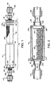
- a device 10 is shown in a horizontal orientation.
- the features and operation of the device 10 are described on the basis of a horizontal orientation, and the terms “top”, “bottom”, “upper”, “lower” etc. are used to refer to various features of the device 10 for simplicity.
- the device 10 may be positioned in a horizontal, sloping, or vertical orientation without affecting the nature of the invention.
- the use of the terms “top”, “bottom”, “upper”, “lower” etc. are therefore not to be considered as limiting.
- the device 10 comprises a housing 20 which consists of a hollow cylinder having an inlet opening 80 at one end and an outlet opening 90 at the other end.
- the housing 20 contains a cartridge 30 which itself contains a neutralising agent 280 in solid form.
- the neutralising agent 280 comprises calcium carbonate chippings.
- any other suitable neutralising agent may be used, for example, sodium metaborate or magnesium carbonate.
- the cartridge 30 has a fluid permeable cap 40, and the housing 20 has first and second end caps 50, 60.
- the end caps 50, 60 facilitate connection of the device 10 to a pipe work system as will be described in grater detail below.
- the housing 20, cartridge 30, cartridge cap 40, and end caps 50, 60 are each aligned on a common axis 70 and are preferably made from a moulded plastic such as polypropylene.
- First and second end caps 50, 60 define an inlet 100 and an outlet 110 respectively.
- the end caps 50, 60 are provided with annular flanges 120 and 130 which fittingly engage with the inlet and outlet openings 80, 90 of the housing 20.
- End caps 50, 60 are also provided with external screw threads 140, 150 for engagement with connectors 160, 170 as will be described in greater detail below.
- the device 10 is arranged to be attached to an existing pipe work system via the connectors 160, 170.
- the connectors 160, 170 each comprise collars 180, 190 which have internal screw threads 200, 210 for connection to screw threads 140, 150 of the end caps 50, 60.
- connector 160 attaches to a condensate pipe (not shown) leading from the boiler (not shown)
- connector 170 attaches to a pipe (not shown) leading to the drain.
- the connectors 160, 170 shown in Figures 1 and 2 are standard commercially available connectors which are well known to persons skilled in the art. It will be appreciated that any other suitable connector could be used.
- the device 10 is fitted into existing pipe work by connecting collars 180, 190 to threads 140, 150, respectively, of end caps 50, 60.
- the reverse process is used to remove the device 10.
- the cartridge 30 comprises a hollow tapered cylinder which is open at a first, inlet, end 220, and closed at the other end 230.
- An annular flange 240 is provided at the first end 220. As shown in Figure 2 , the annular flange 240 is sized to fittingly engage with the inner surface of the housing 20.
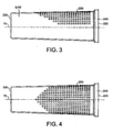
- the cartridge 30 is provided with a pattern of perforations 250 located, according to the orientation of Figure 3 , on the upper half of the cartridge 30.
- the perforations 250 are square in cross-section and arranged in rows which extend substantially from the first end 220 of the cartridge 30 towards the closed end 230.
- the rows of perforations 250 each stop short of the closed end 230 to define a closed portion 400 proximate the closed end 230 of the cartridge 30.
- the rows of perforations 250 located at the outermost edge of the pattern are the shortest rows, having the least number of perforations 250, and the centremost row is the longest row, the rows increasing in length between the edges of the pattern and its centre.
- the pattern of perforations described above is only one example of the configurations possible.
- the perforations 250 may be circular in cross-section, or any other suitable shape, and that the rows may be of equal length or may increase in length from the centre of the pattern to the edges.
- a symmetrical pattern is preferred, its is not essential to the invention that the pattern of perforations is symmetric.
- the perforations 250 are located on the upper half of the cartridge 30 only.
- the perforations 250 extend around half or less than half of the circumference of the cartridge 30.
- the rows of perforations 250 preferably extend only part of the way along the cartridge 30 from the open end to 250 to the closed end 230 and stop short of the closed end 240. In this way, whether the cartridge 30 is horizontal as shown in Figure 1 , or vertical or sloping with the open end 220 uppermost, a certain volume is defined in the closed part of the cartridge 30 below the level of the perforations 250.
- the cap 40 of the cartridge 30 comprises a fluid permeable structure 260.
- the fluid permeable structure is a mesh.
- the cap 40 comprises an annular flange 270 which is sized to fittingly engage within the opening 220 at the first end of the cartridge 30.
- the cap 40 retains the calcium carbonate chippings within the cartridge 30 when it is not installed in the housing 20. If desired, the cap 40 may be removable to allow replacement of the calcium carbonate chippings 280.
- the cartridge 30, complete with chippings 280 and cap 40 is inserted into the housing 20, with the end cap 60 already in place, through the inlet opening 80.
- the other end cap 50 is then fitted into the inlet opening 80.
- the closed end 230 of the cartridge 30 is held in place within the housing 20 by projections 290, 300 on the end cap 60, the open end 220 of the cartridge 30 being held in place by the engagement of flange 240 with the inner surface of the housing 20.
- condensate from a condensing boiler enters the device 10 through the inlet 100 and then passes through mesh 260 into the cartridge 30 where it comes into contact with the calcium carbonate chippings 280. Because the end 230 and lower half of the cartridge is closed, it is not possible for the condensate to flow out of the cartridge until the volume of condensate within the cartridge has reached a minimum level. When the minimum volume has been reached, the condensate is able to flow from the interior of the cartridge 30 into an area 310 located between the cartridge 30 and the housing 20. The length of time that the condensate spends in contact with the calcium carbonate chippings 280 is thereby increased when compared with existing devices.
- the device 10 may be positioned in a vertical orientation, with the inlet opening 80 uppermost.
- the condensate flows into the device 10 through the inlet 100 and into the cartridge 30 via mesh 260.
- the condensate then fills the lowermost portion of the cartridge 30 proximate the closed end 230.
- the level of condensate within the cartridge 30 reaches the lowermost perforations (at the tip of the pattern as illustrated in Figure 4 ) it is able to flow into area 310 and then out of the device 10 through outlet 110.
- the device 10 my be installed in a sloping configuration with the inlet opening 80 uppermost.
- the closed portion of the cartridge 30 is effective as a weir. Therefore, certain volume of condensate must fill the cartridge 30 and contact the chippings 280 before any condensate can flow out of the cartridge 30.
- the device 10 described above may be disposable.
- the cartridge 30 and/or the chippings 280 may be replaceable.
Landscapes
- Chemical & Material Sciences (AREA)
- Life Sciences & Earth Sciences (AREA)
- Hydrology & Water Resources (AREA)
- Engineering & Computer Science (AREA)
- Environmental & Geological Engineering (AREA)
- Water Supply & Treatment (AREA)
- Organic Chemistry (AREA)
- Health & Medical Sciences (AREA)
- Medicinal Chemistry (AREA)
- Chemical Kinetics & Catalysis (AREA)
- Treatment Of Water By Ion Exchange (AREA)
- Physical Or Chemical Processes And Apparatus (AREA)
Applications Claiming Priority (1)
| Application Number | Priority Date | Filing Date | Title |
|---|---|---|---|
| GB0814804A GB2464660A (en) | 2008-08-13 | 2008-08-13 | Device for chemically treating condensate from a domestic boiler |
Publications (2)
| Publication Number | Publication Date |
|---|---|
| EP2154113A2 true EP2154113A2 (fr) | 2010-02-17 |
| EP2154113A3 EP2154113A3 (fr) | 2010-04-28 |
Family
ID=39790720
Family Applications (1)
| Application Number | Title | Priority Date | Filing Date |
|---|---|---|---|
| EP09251987A Withdrawn EP2154113A3 (fr) | 2008-08-13 | 2009-08-13 | Dispositif pour le traitement chimique de condensats à partir d'une chaudière domestique |
Country Status (2)
| Country | Link |
|---|---|
| EP (1) | EP2154113A3 (fr) |
| GB (1) | GB2464660A (fr) |
Cited By (1)
| Publication number | Priority date | Publication date | Assignee | Title |
|---|---|---|---|---|
| ITUB20160284A1 (it) * | 2016-02-02 | 2017-08-02 | Crea Srl | Dispositivo neutralizzatore per neutralizzare acqua di condensa acida prodotta da una caldaia a condensazione |
Citations (1)
| Publication number | Priority date | Publication date | Assignee | Title |
|---|---|---|---|---|
| GB2425739A (en) | 2005-04-07 | 2006-11-08 | Salamander | Condensate treatment |
Family Cites Families (12)
| Publication number | Priority date | Publication date | Assignee | Title |
|---|---|---|---|---|
| JPS5864423A (ja) * | 1981-10-13 | 1983-04-16 | Matsushita Electric Ind Co Ltd | 燃焼装置 |
| JPS58122086A (ja) * | 1982-01-18 | 1983-07-20 | Matsushita Electric Ind Co Ltd | 酸性結露水の中和処理装置 |
| JPS5974324A (ja) * | 1982-10-21 | 1984-04-26 | Yanmar Diesel Engine Co Ltd | 内燃機関のドレン水処理装置 |
| JPH06190378A (ja) * | 1992-12-28 | 1994-07-12 | Tokyo Gas Co Ltd | 排気ドレン中和装置 |
| JP3983912B2 (ja) * | 1998-01-30 | 2007-09-26 | 日本ゼオライト株式会社 | アルカリイオン水製造用多孔質セラミックス、該多孔質セラミックスの製造方法及びアルカリイオン水生成器 |
| JPH11277077A (ja) * | 1998-03-31 | 1999-10-12 | Noritz Corp | 中和装置 |
| JP2003144821A (ja) * | 2001-11-09 | 2003-05-20 | Inax Corp | 活性炭フィルタ、浄水カートリッジ及び浄水器 |
| PT1706359E (pt) * | 2004-01-23 | 2011-02-24 | Marchi & Brevetti Interprise S R L | Um dispositivo para dissolver substâncias sólidas em água |
| JP2006175301A (ja) * | 2004-12-20 | 2006-07-06 | Noritz Corp | 凝縮水中和器およびこれを備えた給湯装置 |
| JP4701755B2 (ja) * | 2005-03-09 | 2011-06-15 | 株式会社ノーリツ | 凝縮水中和器およびこれを備えた給湯装置 |
| JP2006266560A (ja) * | 2005-03-23 | 2006-10-05 | Matsushita Electric Ind Co Ltd | 給湯暖房装置 |
| CN101360439B (zh) * | 2006-01-20 | 2012-02-22 | Pi-设计公开股份公司 | 滤芯 |
-
2008
- 2008-08-13 GB GB0814804A patent/GB2464660A/en not_active Withdrawn
-
2009
- 2009-08-13 EP EP09251987A patent/EP2154113A3/fr not_active Withdrawn
Patent Citations (1)
| Publication number | Priority date | Publication date | Assignee | Title |
|---|---|---|---|---|
| GB2425739A (en) | 2005-04-07 | 2006-11-08 | Salamander | Condensate treatment |
Cited By (1)
| Publication number | Priority date | Publication date | Assignee | Title |
|---|---|---|---|---|
| ITUB20160284A1 (it) * | 2016-02-02 | 2017-08-02 | Crea Srl | Dispositivo neutralizzatore per neutralizzare acqua di condensa acida prodotta da una caldaia a condensazione |
Also Published As
| Publication number | Publication date |
|---|---|
| GB0814804D0 (en) | 2008-09-17 |
| EP2154113A3 (fr) | 2010-04-28 |
| GB2464660A (en) | 2010-04-28 |
Similar Documents
| Publication | Publication Date | Title |
|---|---|---|
| AU692032B2 (en) | Septic tank effluent filtering method | |
| CN215876366U (zh) | 再生介质过滤容器 | |
| CA2714300A1 (fr) | Recipient de filtration de liquide, dote d'une fenetre de sortie d'air | |
| KR101236062B1 (ko) | 다상흐름식 탈취장치 | |
| JP2010104932A (ja) | 散気装置 | |
| US8795600B2 (en) | UV disinfection system | |
| TW201517970A (zh) | 具有氣泡防止構造的水瓶過濾器 | |
| GB2464660A (en) | Device for chemically treating condensate from a domestic boiler | |
| US8864998B1 (en) | Bead fluid treatment self-cleaning apparatus and method | |
| EP3388396B1 (fr) | Dispositif de purification de liquide | |
| KR100906743B1 (ko) | 배수지 또는 정수지에 사용되는 용수저장탱크 | |
| EP1558531A1 (fr) | Procede et reacteur pour l'adoucissement d'eau et l'elimination simultanee de substances polluantes | |
| EP1820563A1 (fr) | Filtre, jeu de remplacement pour un filtre et procédé de filtrage de liquides | |
| AU2005231684B2 (en) | Tankage system incorporating adsorption clarification and parallel plate separation | |
| JP3554286B2 (ja) | ろ過分離円筒膜カートリッジ | |
| CN205803207U (zh) | 一种污水处理装置 | |
| KR101861614B1 (ko) | 정수기 필터 | |
| KR100528633B1 (ko) | 유동 활성탄을 이용한 오·폐수 정화용 활성탄조 | |
| CN206033427U (zh) | 一种生活污水处理回用系统 | |
| CN214270451U (zh) | 油墨印刷废水处理装置 | |
| JPH07289813A (ja) | 排水処理装置 | |
| KR101728983B1 (ko) | 고도처리용 하폐수 가압식 여과기 | |
| CN2801777Y (zh) | 一种家庭污水处理器 | |
| KR100937357B1 (ko) | 탈취용 아쿠아 필터장치 | |
| CN201016097Y (zh) | 氨氮吹脱装置 |
Legal Events
| Date | Code | Title | Description |
|---|---|---|---|
| PUAI | Public reference made under article 153(3) epc to a published international application that has entered the european phase |
Free format text: ORIGINAL CODE: 0009012 |
|
| AK | Designated contracting states |
Kind code of ref document: A2 Designated state(s): AT BE BG CH CY CZ DE DK EE ES FI FR GB GR HR HU IE IS IT LI LT LU LV MC MK MT NL NO PL PT RO SE SI SK SM TR |
|
| AX | Request for extension of the european patent |
Extension state: AL BA RS |
|
| PUAL | Search report despatched |
Free format text: ORIGINAL CODE: 0009013 |
|
| AK | Designated contracting states |
Kind code of ref document: A3 Designated state(s): AT BE BG CH CY CZ DE DK EE ES FI FR GB GR HR HU IE IS IT LI LT LU LV MC MK MT NL NO PL PT RO SE SI SK SM TR |
|
| AX | Request for extension of the european patent |
Extension state: AL BA RS |
|
| RIC1 | Information provided on ipc code assigned before grant |
Ipc: C02F 1/66 20060101ALN20100325BHEP Ipc: C02F 1/68 20060101ALI20100325BHEP Ipc: C02F 1/00 20060101AFI20091106BHEP |
|
| 17P | Request for examination filed |
Effective date: 20101028 |
|
| 17Q | First examination report despatched |
Effective date: 20101125 |
|
| STAA | Information on the status of an ep patent application or granted ep patent |
Free format text: STATUS: THE APPLICATION IS DEEMED TO BE WITHDRAWN |
|
| 18D | Application deemed to be withdrawn |
Effective date: 20110406 |