EP2154286A2 - Stabilisator und Waschmaschine mit diesem Stabilisator - Google Patents
Stabilisator und Waschmaschine mit diesem Stabilisator Download PDFInfo
- Publication number
- EP2154286A2 EP2154286A2 EP09167256A EP09167256A EP2154286A2 EP 2154286 A2 EP2154286 A2 EP 2154286A2 EP 09167256 A EP09167256 A EP 09167256A EP 09167256 A EP09167256 A EP 09167256A EP 2154286 A2 EP2154286 A2 EP 2154286A2
- Authority
- EP
- European Patent Office
- Prior art keywords
- ball
- drum
- motion space
- members
- ball balancer
- Prior art date
- Legal status (The legal status is an assumption and is not a legal conclusion. Google has not performed a legal analysis and makes no representation as to the accuracy of the status listed.)
- Granted
Links
Images


Classifications
-
- D—TEXTILES; PAPER
- D06—TREATMENT OF TEXTILES OR THE LIKE; LAUNDERING; FLEXIBLE MATERIALS NOT OTHERWISE PROVIDED FOR
- D06F—LAUNDERING, DRYING, IRONING, PRESSING OR FOLDING TEXTILE ARTICLES
- D06F37/00—Details specific to washing machines covered by groups D06F21/00 - D06F25/00
- D06F37/20—Mountings, e.g. resilient mountings, for the rotary receptacle, motor, tub or casing; Preventing or damping vibrations
- D06F37/22—Mountings, e.g. resilient mountings, for the rotary receptacle, motor, tub or casing; Preventing or damping vibrations in machines with a receptacle rotating or oscillating about a horizontal axis
- D06F37/225—Damping vibrations by displacing, supplying or ejecting a material, e.g. liquid, into or from counterbalancing pockets
-
- D—TEXTILES; PAPER
- D06—TREATMENT OF TEXTILES OR THE LIKE; LAUNDERING; FLEXIBLE MATERIALS NOT OTHERWISE PROVIDED FOR
- D06F—LAUNDERING, DRYING, IRONING, PRESSING OR FOLDING TEXTILE ARTICLES
- D06F37/00—Details specific to washing machines covered by groups D06F21/00 - D06F25/00
- D06F37/02—Rotary receptacles, e.g. drums
- D06F37/04—Rotary receptacles, e.g. drums adapted for rotation or oscillation about a horizontal or inclined axis
- D06F37/06—Ribs, lifters, or rubbing means forming part of the receptacle
-
- D—TEXTILES; PAPER
- D06—TREATMENT OF TEXTILES OR THE LIKE; LAUNDERING; FLEXIBLE MATERIALS NOT OTHERWISE PROVIDED FOR
- D06F—LAUNDERING, DRYING, IRONING, PRESSING OR FOLDING TEXTILE ARTICLES
- D06F37/00—Details specific to washing machines covered by groups D06F21/00 - D06F25/00
- D06F37/26—Casings; Tubs
- D06F37/267—Tubs specially adapted for mounting thereto components or devices not provided for in preceding subgroups
- D06F37/268—Tubs specially adapted for mounting thereto components or devices not provided for in preceding subgroups for suspension devices
-
- D—TEXTILES; PAPER
- D06—TREATMENT OF TEXTILES OR THE LIKE; LAUNDERING; FLEXIBLE MATERIALS NOT OTHERWISE PROVIDED FOR
- D06F—LAUNDERING, DRYING, IRONING, PRESSING OR FOLDING TEXTILE ARTICLES
- D06F39/00—Details of washing machines not specific to a single type of machines covered by groups D06F9/00 - D06F27/00
- D06F39/12—Casings; Tubs
- D06F39/125—Supporting arrangements for the casing, e.g. rollers or legs
-
- F—MECHANICAL ENGINEERING; LIGHTING; HEATING; WEAPONS; BLASTING
- F16—ENGINEERING ELEMENTS AND UNITS; GENERAL MEASURES FOR PRODUCING AND MAINTAINING EFFECTIVE FUNCTIONING OF MACHINES OR INSTALLATIONS; THERMAL INSULATION IN GENERAL
- F16F—SPRINGS; SHOCK-ABSORBERS; MEANS FOR DAMPING VIBRATION
- F16F15/00—Suppression of vibrations in systems; Means or arrangements for avoiding or reducing out-of-balance forces, e.g. due to motion
- F16F15/10—Suppression of vibrations in rotating systems by making use of members moving with the system
- F16F15/16—Suppression of vibrations in rotating systems by making use of members moving with the system using a fluid or pasty material
-
- F—MECHANICAL ENGINEERING; LIGHTING; HEATING; WEAPONS; BLASTING
- F16—ENGINEERING ELEMENTS AND UNITS; GENERAL MEASURES FOR PRODUCING AND MAINTAINING EFFECTIVE FUNCTIONING OF MACHINES OR INSTALLATIONS; THERMAL INSULATION IN GENERAL
- F16F—SPRINGS; SHOCK-ABSORBERS; MEANS FOR DAMPING VIBRATION
- F16F15/00—Suppression of vibrations in systems; Means or arrangements for avoiding or reducing out-of-balance forces, e.g. due to motion
- F16F15/32—Correcting- or balancing-weights or equivalent means for balancing rotating bodies, e.g. vehicle wheels
- F16F15/36—Correcting- or balancing-weights or equivalent means for balancing rotating bodies, e.g. vehicle wheels operating automatically, i.e. where, for a given amount of imbalance, there is movement of masses until balance is achieved
- F16F15/363—Correcting- or balancing-weights or equivalent means for balancing rotating bodies, e.g. vehicle wheels operating automatically, i.e. where, for a given amount of imbalance, there is movement of masses until balance is achieved using rolling bodies, e.g. balls free to move in a circumferential direction
-
- Y—GENERAL TAGGING OF NEW TECHNOLOGICAL DEVELOPMENTS; GENERAL TAGGING OF CROSS-SECTIONAL TECHNOLOGIES SPANNING OVER SEVERAL SECTIONS OF THE IPC; TECHNICAL SUBJECTS COVERED BY FORMER USPC CROSS-REFERENCE ART COLLECTIONS [XRACs] AND DIGESTS
- Y02—TECHNOLOGIES OR APPLICATIONS FOR MITIGATION OR ADAPTATION AGAINST CLIMATE CHANGE
- Y02B—CLIMATE CHANGE MITIGATION TECHNOLOGIES RELATED TO BUILDINGS, e.g. HOUSING, HOUSE APPLIANCES OR RELATED END-USER APPLICATIONS
- Y02B40/00—Technologies aiming at improving the efficiency of home appliances, e.g. induction cooking or efficient technologies for refrigerators, freezers or dish washers
-
- Y—GENERAL TAGGING OF NEW TECHNOLOGICAL DEVELOPMENTS; GENERAL TAGGING OF CROSS-SECTIONAL TECHNOLOGIES SPANNING OVER SEVERAL SECTIONS OF THE IPC; TECHNICAL SUBJECTS COVERED BY FORMER USPC CROSS-REFERENCE ART COLLECTIONS [XRACs] AND DIGESTS
- Y10—TECHNICAL SUBJECTS COVERED BY FORMER USPC
- Y10T—TECHNICAL SUBJECTS COVERED BY FORMER US CLASSIFICATION
- Y10T74/00—Machine element or mechanism
- Y10T74/21—Elements
- Y10T74/211—Eccentric
- Y10T74/2111—Plural, movable relative to each other [including ball[s]]
Definitions
- the present invention relates to a ball balancer and a laundry apparatus having the same. More particularly, the present invention relates to a ball balancer capable of reducing noise and vibration of a laundry apparatus and a laundry apparatus having the same.
- laundry apparatuses are home appliances that are used to remove dirt and foreign substances of clothes, cloth items and the like (hereinafter, laundry) which are put on by users.
- a laundry apparatus may be a washing machine and a dryer and a single appliance that performs washing and drying operation.
- Such the laundry apparatus includes an oriented rotatable drum within a cabinet defining an exterior appearance thereof. The drum is rotating and washing or drying operation is performed. The washing operation includes a washing, rinsing and drying-spinning cycle.
- the present invention is invented to solve the above problem and to provide a laundry apparatus able to reduce noise and vibration.
- Another object of the present invention is to provide a control method of a laundry apparatus able to reduce noise and vibration in case a drum is rotated at a high rotation number, for example, a drying-spinning cycle.
- the present invention is directed to a ball balancer and a laundry apparatus having the same.
- An object of the present invention is to provide a ball balancer able to reduce noise and vibration.
- Another object of the present invention is to provide a laundry apparatus able to reduce noise and vibration in case a drum is rotated at a high rotation number, for example, a drying-spinning cycle.
- a ball balancer includes a circular housing comprising motion space formed therein; at least two partition members spaced apart a predetermined distance along the motion space of the housing, the partition members partitioning the motion space into at least two spaces; a plurality of ball members movable within the partitioned spaces of the motion space; and viscous fluid filled in the motion space.
- the viscous fluid may be able to pass the partition members and the ball members may be unable to pass the partition members.
- the partition member may be configured of a rib or boss.
- the plurality of the ball members may be distributed in the partitioned spaces of the motion space uniformly.
- a laundry apparatus in another aspect of the present invention, includes a drum receiving laundry therein, the drum comprising a plurality of lifters extending inward; a circular housing provided in an outer surface of the drum, the circular housing comprising motion space formed therein; at least two partition members spaced apart a predetermined distance along the motion space of the housing, the at least two partition members alternating with the plurality of the lifters in a semi-circumferential direction, respectively, and partitioning the motion space into at least two spaces; and a plurality of ball members movable within the partitioned spaces of the motion space.
- Each of the partition members may be arranged in a center of each adjacent two of the plurality of the lifters.
- the laundry apparatus may further include viscous fluid filled in the motion space.
- the viscous fluid may be able to pass the partition members may be unable to pass the partition members.
- the partition member may be configured of a rib or boss.
- the plurality of the ball members may be distributed in the partitioned spaces uniformly.
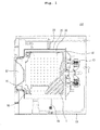
- FIG. 1 is a side sectional view illustrating a laundry apparatus according to an exemplary embodiment of the present invention
- FIG. 2 is a perspective view partially illustrating a ball balancer shown in FIG. 1 ;
- FIG. 3 is a diagram schematically illustrating a configuration of a ball balancer according to a first embodiment of the present invention
- FIG. 4 is a diagram schematically illustrating a configuration of a ball balancer according to a second embodiment of the present invention.
- FIG. 5 is a diagram schematically illustrating an inner configuration of the laundry apparatus shown in FIG. 1 ;
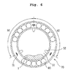
- FIG. 6 is a diagram schematically illustrating an inner configuration of a laundry apparatus having different components from the laundry apparatus shown in FIG. 1 .
- FIG. 1 is a side sectional view illustrating an inner configuration of a laundry apparatus according to an exemplary embodiment of the present invention.
- a laundry apparatus 100 includes a cabinet 10, a tub 20 and a drum 30.
- the cabinet 10 defines an exterior appearance of the laundry apparatus.
- the tub 20 is provided in the cabinet 10 and it receives wash water therein.
- the drum 20 is rotatable within the tub 20.
- a door 12 is coupled to a front of the cabinet 10 and a user will open the door 12 to introduce laundry into the cabinet 10.
- the tub 20 receiving wash water is provided in the cabinet 10 and the drum 30 receiving laundry is rotatably provided in the tub 20.
- a plurality of lifters 32 may be provided in the drum 30.
- the lifters 30 lift and drop the laundry to improve washing efficiency.
- Such the lifter 32 may be provided in plural.
- the laundry apparatus 100 includes three lifters 32 provided in the drum 30 and the number of the lifters 32 may be variable, not limited thereto.
- the tub 20 is elastically supported by a spring 50 and a damper 60.
- vibration of the drum 30 is absorbed by the spring 50 and the damper 60 such that such the vibration may not be transmitted to the cabinet 10.
- a driving part 40 rotating the drum 30 is mounted to a rear of the tub 20 and the driving part 40 is configured of a motor to driving the drum 30 selectively.
- the configuration of such the driving part 40 is well-known in the art which the present invention pertains to and detailed description thereof will be omitted accordingly.
- a ball balancer 70 may be provided in the drum 30.
- the ball balancer 70 is provided in the rotating drum 30 and it is preferable that the ball balancer 70 is provided in a front of the drum 30. If the drum 30 is rotated at a high rotation number, for example, in a spinning cycle, the laundry would be collected in one side of the drum 30, that is, an inner rear portion of drum 30 and the ball balancer 70 balances the laundry collected in the rear portion of the drum 30.
- the ball balancer 70 is mounted to the rotating drum 30 to prevent noise and vibration and it may move variously to compensate the eccentric rotation of the drum 30. That is, the ball balancer 70 includes predetermined material having a predetermined weight and a passage of which the material can move along a circumference. If load is concentrated on a predetermined side of the drum 30, the material provided in the ball balancer 70 moves to an opposite direction to the direction in which load is concentrated such that the noise and vibration generated by the eccentric rotation of the drum 30 may be prevented.
- the ball balancer 70 may be a liquid ball balancer having liquid with a predetermined weight or a ball balancer having a ball member with a predetermined weight.
- the laundry apparatus according to this embodiment presents a ball balancer having a ball member and viscous fluid which will be described as follows.
- FIG. 2 is a sectional view illustrating the ball balancer 70 provided in the drum shown in FIG. 1 .
- the ball balancer 70 is secured to the drum 30 and it is rotated together with the drum 30 to compensate the eccentric rotation of the drum 30. That is, the ball balancer 70 according to a first embodiment of the present invention is secured to a front of the drum along an outer circumferential surface of the drum 30.
- the drum 30 is rotated in a state of being fixed to the driving part 40.
- the ball balancer is installed as far from the driving part as possible, a large moment is applied only by the small weight of the ball balancer 70 such that the eccentricity may be compensated.
- the ball balancer 70 is installed in the front surface of the drum to improve the efficiency of the ball balancer 70.
- the present invention is not limited thereto and it is possible to install the ball balancer in a rear of the drum 30.
- the ball balancer 70 may be installed to the drum 30 by a securing member (not shown). generally, it is possible to use a screw member passing the outer circumferential surface of the drum 30 from the front surface of the drum 30 which ends up to be secured to the ball balancer 70.
- a securing member not shown
- the present invention is not limited to the above. Rather than the above presentation, the ball balancer 70 may be installed to the drum by another securing way such as a hook.
- a flange (not shown) extending forward along the outer circumferential surface of the drum may be formed in the front surface of the drum 30 and a seating groove (not shown) may be formed in the front surface of the drum 30. Then, the ball balancer 70 seated in the seating recess is secured to the drum by the securing member and it is rotated together with the drum 30 when the washing apparatus is put into operation.
- such the ball balancer 70 may be configured of a circular housing 74 having motion space 72.
- the housing 74 includes a body 76 having an open side and a cover 78 covering the open side of the body 76. Viscous fluid is injected into the body 76 of the ball balancer 70, together with a ball member 80 which will be descried and the cover 78 is fabricated in the open side of the body 76.
- the ball balancer 70 includes a ball member 80 that is movable to compensate the eccentric rotation of the drum 30.
- a plurality of ball members 80 may be provided in the ball balancer 70 and they are movable along the motion space 72 of the ball balancer 70.
- the housing 74 is formed circularly as mentioned above, the motion space 72 formed along the inside of the housing 74 may be formed along a passage of the circular shape as well.
- the ball member 80 provided in the ball balancer 70 may move along the circular motion space 72 and thus the eccentric rotation of the drum 30 is compensated.
- the number of the ball members 80 injected into the ball balancer 70 may be 10 to 40, for example, and the number may be variable.
- the ball members 80 provided in the ball balancer 70 may compensate the eccentric rotation of the drum 30. However, the ball members 80 would be collided against each other by the rotation of the drum 30 during their motion and this would cause noise. By extension, in case the drum 20 is rotated at the high rotation number, the ball members 80 would be collided against the housing 74 of the ball balancer 70 to result in damage to themselves. As a result, it is preferable that viscous fluid is provided in the ball balancer 70, together with the ball members 80. The viscous fluid may fill in the motion space 72 of the ball balancer 70 to prevent the rapid motion of the ball members 80 such that the noise and damage to the ball balancer 70 may be prevented. Such the viscous fluid may be configured of fluid having a predetermined weight, for example, silicon oil or the like.
- the ball balancer 70 having the above configuration may be provided in the front of the drum 30. in case the drum 30 is rotated, especially, at the high rotation speed such as during the spinning cycle, the ball members 80 provided in the ball balancer 70 may move toward an opposite direction to the laundry received in the drum 30 and it may prevent the noise and the vibration caused by the eccentric rotation of the drum 30.
- the motion space 72 is a single space in communication in case of the ball members 80 being moved along the motion space 72 by the rotation of the drum 30, all of the ball members provided in the ball balancer 70 80 would be collected in one side. if all of the ball members 80 are collected in one side during the motion of the ball members 80 along the inside of the ball balancer 70 in case of a relatively large amount of laundry, the ball members and the laundry may be in balance. In case of a relatively small amount of laundry, the noise and vibration of the drum 30 may be accelerated by the ball members 80 collected in one side.
- the ball balancer 70 may include at least two partition members (71, see FIG. 3 ) formed along the inside of the housing 72 and partitioning the motion space 72 into at least two spaces.
- FIG. 3 illustrates a configuration of a ball balancer according to a first embodiment.
- the partition members 71 are arranged along the motion space 72, spaced apart a predetermined distance from each other, such that the motion space 72 may be partitioned into at least two spaces.
- three partition members 72 are provided and they partition the motion space 72 into threes spaces.
- the number of the partition members is not limited to three and it may be variable appropriately.
- the ball members 80 provided in the ball balancer 70 may be arranged in the partitioned motion space uniformly.
- the ball members 80 arranged in the partitioned motion space 72 uniformly may be movable along the partitioned motion space 72 which they have arranged primarily and they may not pass the partition member 71.
- the ball members 80 may not be collected in one side within the motion space 72 during the rotation of the drum 30 and the noise and vibration caused by the eccentric rotation of the drum 30 may be prevented efficiently.
- such the partition members 71 may be provided along the inside of the housing 74 in a circumferential direction of the housing 74. That is, as shown in FIG. 3 , the partition members 71 may be ribs having a predetermined length in a circumferential direction of the housing 74. Because of the ribs 71 partitioning the motion space 71 into three spaces, the ball members 80 provided in the housing 74 may not move over one of the motion space 72 partitioned by the ribs 71 and the viscous fluid (not shown) filled in the housing 74 may move regardless of the ribs 71.
- the ball members 80 provided in the ball balancer 70 may be movable along the spaces of the motion space 72 partitioned by the partition members 71 and the viscous fluid filled in the ball balancer 70 may be movable regardless of the partition members 71, such that the noise and vibration caused by the eccentric rotation of the drum 30 may be prevented.
- FIG. 4 is a diagram schematically illustrating a configuration of a ball balancer 170 according to a second embodiment of the present invention.
- the ball balancer 170 according to this embodiment of FIG. 4 is different from the ball balancer 70 according to above embodiment of FIG. 3 .
- partition members 171 partitioning the motion space 72 inside the ball balancer 170 may be bosses 171 projected from an inner space of the housing 74. Such the bosses 171 may be formed along a circumferential direction of the housing 74 to limit the motion of the ball members 80, allowing the motion of the viscous fluid.
- the ball balancer 70 having the above configuration may be mounted to a lower portion of the front surface of the drum 30. If then, the motion space 72 formed in the ball balancer 70 may be partitioned by the motion members 71 and thus it is preferable that the ball balancer 70 is mounted to the drum in consideration of the partition members 71.
- the drum 30 includes the lifters 32 lifting and dropping the laundry and the laundry is typically positioned in space between the lifters 32 during the rotation of the drum 30 at the high rotation numbers.
- the ball balancer 70 is installed in consideration of the arrangement of the lifters 32 and the partition members 71, which will be described in detail in reference to a corresponding drawing.
- FIG. 6 is a diagram schematically illustrating a laundry apparatus including the ball balancer 70 mounted to the drum 30 only to accelerate the noise and vibration.
- the partition members 71 provided in the ball balancer 70 accord with the lifters 32 provided in the drum 30 in a semi-circumferential direction. If the ball balancer 70 is installed as mentioned above, the ball members 80 inside the ball balancer 70 are collected opposite to the laundry positioned in the space between lower lifters 32 of the drum during the rotation of the drum 30 at the high rotation number. All of the ball members 80 arranged in the adjacent partitioned spaces 90 and 92 are moved to the portion opposite to the laundry and collected with respect to the uppermost partition member 71 shown in FIG. 6 .
- the drum 30 would be rotated eccentrically by the laundry distributed not uniformly. That is, the ball members 80 collected in one side of the ball balancer 70 would cause more noise and vibration during the rotation of the drum 30.
- the partition members 71 of the ball balancer 70 and the lifters 32 of the drum 30 are alternating in a semi-circumferential direction, respectively, according to the exemplary embodiment of the laundry apparatus.
- the partition members 71 provided in the ball balancer 70 alternate with the lifters 32 of the drum 30, respectively. It is preferable that the ball balancer 70 is mounted to the drum 30, with each partition member 71 of the ball balancer 70 positioned at a center between each two lifters 32 in a semi-circumferential direction.
- the ball balancer 70 is mounted to the drum 30 as mentioned above, the noise and vibration may not be accelerated by the ball members 80 collected in one side of the ball balancer 70.
- the ball members 80 of the ball balancer 70 are collected opposite to the laundry 1.
- each partition member 71 is positioned between each two adjacent two lifters 32.
- the ball members 80 arranged in the partitioned motion space 90 are moved direct opposite to the laundry 1.
- the ball members 80 arranged in the partitioned spaces adjacent to the space 90 opposite to the laundry may be moved to a portion closest to the opposite space, that is, toward the partition members 71 opposite to the laundry although not moved to the space direct opposite to the laundry.
- the partition members 71 of the ball balancer 70 are alternating with the lifters 32 of the drum 30, respectively, the entire ball members 80 inside the ball balancer 70 are not collected in the one side and thus the noise and vibration may not be accelerated.
- the ball balancer is controlled and the noise and vibration of the laundry apparatus may be reduced noticeably.
- the noise and vibration may be reduced noticeably.
Landscapes
- Engineering & Computer Science (AREA)
- Textile Engineering (AREA)
- General Engineering & Computer Science (AREA)
- Physics & Mathematics (AREA)
- Acoustics & Sound (AREA)
- Aviation & Aerospace Engineering (AREA)
- Mechanical Engineering (AREA)
- Main Body Construction Of Washing Machines And Laundry Dryers (AREA)
Applications Claiming Priority (1)
| Application Number | Priority Date | Filing Date | Title |
|---|---|---|---|
| KR1020080076922A KR101537590B1 (ko) | 2008-08-06 | 2008-08-06 | 볼 밸런서 및 이를 구비한 세탁장치 |
Publications (3)
| Publication Number | Publication Date |
|---|---|
| EP2154286A2 true EP2154286A2 (de) | 2010-02-17 |
| EP2154286A3 EP2154286A3 (de) | 2016-11-30 |
| EP2154286B1 EP2154286B1 (de) | 2021-10-13 |
Family
ID=41162723
Family Applications (1)
| Application Number | Title | Priority Date | Filing Date |
|---|---|---|---|
| EP09167256.8A Active EP2154286B1 (de) | 2008-08-06 | 2009-08-05 | Stabilisator und Waschmaschine mit diesem Stabilisator |
Country Status (4)
| Country | Link |
|---|---|
| US (1) | US8739579B2 (de) |
| EP (1) | EP2154286B1 (de) |
| KR (1) | KR101537590B1 (de) |
| CN (1) | CN101643992B (de) |
Cited By (3)
| Publication number | Priority date | Publication date | Assignee | Title |
|---|---|---|---|---|
| EP2910673A3 (de) * | 2014-02-19 | 2015-11-18 | Samsung Electronics Co., Ltd. | Waschmaschine mit Ausgleichsreglern und Steuerungsverfahren dafür |
| IT201700037265A1 (it) * | 2017-04-05 | 2018-10-05 | Antonio Francesco Chiriatti | Bilanciatore per controllo attivo di sbilanciamento in un elettrodomestico |
| WO2018184734A1 (en) * | 2017-04-05 | 2018-10-11 | Antonio Chiriatti | Laundry treating apparatus |
Families Citing this family (8)
| Publication number | Priority date | Publication date | Assignee | Title |
|---|---|---|---|---|
| KR101674526B1 (ko) * | 2010-10-06 | 2016-11-10 | 삼성전자주식회사 | 세탁기와 그 제어방법 |
| KR101607867B1 (ko) * | 2011-07-27 | 2016-04-01 | 삼성전자 주식회사 | 세탁기와 그 밸런서 |
| EP2708628B1 (de) * | 2012-09-12 | 2015-09-02 | Samsung Electronics Co., Ltd | Waschmaschine |
| KR102105848B1 (ko) * | 2013-02-01 | 2020-05-04 | 삼성전자주식회사 | 밸런서를 구비한 세탁기 및 그 제어방법 |
| KR101660102B1 (ko) * | 2014-04-08 | 2016-10-04 | 엘에스산전 주식회사 | 용수량 수요 예측 장치 |
| WO2015190659A1 (ko) * | 2014-06-09 | 2015-12-17 | 엘지전자 주식회사 | 세탁장치 |
| CN104060443B (zh) * | 2014-06-19 | 2016-08-24 | 无锡小天鹅通用电器有限公司 | 平衡圈及其滚筒洗衣机 |
| KR102648272B1 (ko) * | 2018-10-30 | 2024-03-14 | 엘지전자 주식회사 | 세탁물 처리기기 및 그의 제어방법 |
Family Cites Families (15)
| Publication number | Priority date | Publication date | Assignee | Title |
|---|---|---|---|---|
| CA1056736A (en) * | 1975-04-18 | 1979-06-19 | Gentaro Hayashi | Balancing construction for centrifugal extractor |
| JPS5836593A (ja) * | 1981-08-26 | 1983-03-03 | 株式会社東芝 | 遠心回転機用バランサ |
| US4711610A (en) * | 1986-04-04 | 1987-12-08 | Machine Technology, Inc. | Balancing chuck |
| KR100224450B1 (ko) | 1996-05-23 | 1999-10-15 | 윤종용 | 드럼세탁기의 밸런싱장치 |
| TW381135B (en) * | 1996-06-03 | 2000-02-01 | Samsung Electronics Co Ltd | Washing machine with ball balancer |
| KR100222947B1 (ko) * | 1997-01-09 | 1999-10-01 | 윤종용 | 볼밸런서 |
| WO1999010583A1 (en) * | 1997-08-21 | 1999-03-04 | Eti Technologies Inc. | Balancing device for use on washing machines |
| WO1999016070A1 (en) * | 1997-09-25 | 1999-04-01 | Matsushita Electric Industrial Co., Ltd. | Disk drive |
| US6219328B1 (en) * | 1997-10-31 | 2001-04-17 | Funai Electric Co., Ltd. | Disc rotating apparatus |
| SE9704000D0 (sv) * | 1997-10-31 | 1997-10-31 | Electrolux Ab | Kulbalanseringsanordning |
| US6442782B1 (en) * | 2000-04-27 | 2002-09-03 | Maytag Corporation | Ball balancing mechanism |
| US6327732B1 (en) * | 2000-05-10 | 2001-12-11 | Maytag Corporation | Fluid balancing ring and method for using same |
| KR100473492B1 (ko) * | 2002-09-12 | 2005-03-10 | 삼성전기주식회사 | 광디스크 드라이버용 스핀들 모터 |
| KR100513033B1 (ko) * | 2003-03-03 | 2005-09-05 | 엘지전자 주식회사 | 하부 발란서가 구비된 세탁기 |
| KR101362379B1 (ko) * | 2006-06-01 | 2014-02-13 | 삼성전자주식회사 | 밸런서를 구비한 세탁기 |
-
2008
- 2008-08-06 KR KR1020080076922A patent/KR101537590B1/ko active Active
-
2009
- 2009-08-05 EP EP09167256.8A patent/EP2154286B1/de active Active
- 2009-08-05 US US12/461,263 patent/US8739579B2/en active Active
- 2009-08-06 CN CN2009101641331A patent/CN101643992B/zh active Active
Non-Patent Citations (1)
| Title |
|---|
| None * |
Cited By (5)
| Publication number | Priority date | Publication date | Assignee | Title |
|---|---|---|---|---|
| EP2910673A3 (de) * | 2014-02-19 | 2015-11-18 | Samsung Electronics Co., Ltd. | Waschmaschine mit Ausgleichsreglern und Steuerungsverfahren dafür |
| US9809916B2 (en) | 2014-02-19 | 2017-11-07 | Samsung Electronics Co., Ltd. | Washing machine with balancer and control method thereof |
| CN104846581B (zh) * | 2014-02-19 | 2018-10-12 | 三星电子株式会社 | 具有平衡器的洗衣机及其控制方法 |
| IT201700037265A1 (it) * | 2017-04-05 | 2018-10-05 | Antonio Francesco Chiriatti | Bilanciatore per controllo attivo di sbilanciamento in un elettrodomestico |
| WO2018184734A1 (en) * | 2017-04-05 | 2018-10-11 | Antonio Chiriatti | Laundry treating apparatus |
Also Published As
| Publication number | Publication date |
|---|---|
| US20100116003A1 (en) | 2010-05-13 |
| EP2154286B1 (de) | 2021-10-13 |
| US8739579B2 (en) | 2014-06-03 |
| EP2154286A3 (de) | 2016-11-30 |
| CN101643992A (zh) | 2010-02-10 |
| CN101643992B (zh) | 2011-12-21 |
| KR101537590B1 (ko) | 2015-07-22 |
| KR20100018241A (ko) | 2010-02-17 |
Similar Documents
| Publication | Publication Date | Title |
|---|---|---|
| US8739579B2 (en) | Ball balancer and laundry apparatus having the same | |
| EP2154285B1 (de) | Kugel-Ausgleichseinrichtung und Waschmaschine mit dieser | |
| EP3272927B1 (de) | Waschmaschine | |
| EP2602377A1 (de) | Waschmaschine mit einer Knopfanordnung | |
| US20060254321A1 (en) | Washing machine | |
| KR101330732B1 (ko) | 세탁기와 그 밸런서 | |
| CN104321481A (zh) | 辅助洗衣机和使用该辅助洗衣机的衣物处理装置 | |
| KR102471463B1 (ko) | 세탁기 | |
| KR20060081745A (ko) | 드럼세탁기 | |
| CN102587082B (zh) | 洗衣机 | |
| US11629447B2 (en) | Drum-type washing apparatus | |
| KR102482337B1 (ko) | 세탁기 및 가전기기 | |
| KR20110020365A (ko) | 세탁기 및 세탁기의 아우터터브 지지구조 | |
| KR20100078212A (ko) | 세탁장치 | |
| KR20200096030A (ko) | 의류처리장치 및 의류처리장치의 제어방법 | |
| US20120272690A1 (en) | Motor-mounted balance ring for a washing machine appliance | |
| KR20130037408A (ko) | 드럼세탁기 | |
| EP2692933A2 (de) | Trommelwaschmaschine | |
| JP5291128B2 (ja) | 洗濯機 | |
| KR102882227B1 (ko) | 세탁장치 | |
| JP7225227B2 (ja) | 洗濯機 | |
| US20160069011A1 (en) | Top-loading type washing machine | |
| EP2692934A2 (de) | Trommelwaschmaschine | |
| KR101586309B1 (ko) | 드럼세탁기 | |
| KR100591334B1 (ko) | 드럼세탁기 |
Legal Events
| Date | Code | Title | Description |
|---|---|---|---|
| PUAI | Public reference made under article 153(3) epc to a published international application that has entered the european phase |
Free format text: ORIGINAL CODE: 0009012 |
|
| 17P | Request for examination filed |
Effective date: 20090903 |
|
| AK | Designated contracting states |
Kind code of ref document: A2 Designated state(s): AT BE BG CH CY CZ DE DK EE ES FI FR GB GR HR HU IE IS IT LI LT LU LV MC MK MT NL NO PL PT RO SE SI SK SM TR |
|
| PUAL | Search report despatched |
Free format text: ORIGINAL CODE: 0009013 |
|
| AK | Designated contracting states |
Kind code of ref document: A3 Designated state(s): AT BE BG CH CY CZ DE DK EE ES FI FR GB GR HR HU IE IS IT LI LT LU LV MC MK MT NL NO PL PT RO SE SI SK SM TR |
|
| RIC1 | Information provided on ipc code assigned before grant |
Ipc: D06F 37/06 20060101ALI20161021BHEP Ipc: D06F 37/22 20060101AFI20161021BHEP |
|
| STAA | Information on the status of an ep patent application or granted ep patent |
Free format text: STATUS: EXAMINATION IS IN PROGRESS |
|
| 17Q | First examination report despatched |
Effective date: 20200626 |
|
| GRAP | Despatch of communication of intention to grant a patent |
Free format text: ORIGINAL CODE: EPIDOSNIGR1 |
|
| STAA | Information on the status of an ep patent application or granted ep patent |
Free format text: STATUS: GRANT OF PATENT IS INTENDED |
|
| INTG | Intention to grant announced |
Effective date: 20210324 |
|
| GRAJ | Information related to disapproval of communication of intention to grant by the applicant or resumption of examination proceedings by the epo deleted |
Free format text: ORIGINAL CODE: EPIDOSDIGR1 |
|
| STAA | Information on the status of an ep patent application or granted ep patent |
Free format text: STATUS: EXAMINATION IS IN PROGRESS |
|
| INTC | Intention to grant announced (deleted) | ||
| GRAS | Grant fee paid |
Free format text: ORIGINAL CODE: EPIDOSNIGR3 |
|
| STAA | Information on the status of an ep patent application or granted ep patent |
Free format text: STATUS: GRANT OF PATENT IS INTENDED |
|
| GRAP | Despatch of communication of intention to grant a patent |
Free format text: ORIGINAL CODE: EPIDOSNIGR1 |
|
| GRAA | (expected) grant |
Free format text: ORIGINAL CODE: 0009210 |
|
| STAA | Information on the status of an ep patent application or granted ep patent |
Free format text: STATUS: THE PATENT HAS BEEN GRANTED |
|
| INTG | Intention to grant announced |
Effective date: 20210827 |
|
| AK | Designated contracting states |
Kind code of ref document: B1 Designated state(s): AT BE BG CH CY CZ DE DK EE ES FI FR GB GR HR HU IE IS IT LI LT LU LV MC MK MT NL NO PL PT RO SE SI SK SM TR |
|
| REG | Reference to a national code |
Ref country code: GB Ref legal event code: FG4D |
|
| REG | Reference to a national code |
Ref country code: CH Ref legal event code: EP |
|
| REG | Reference to a national code |
Ref country code: DE Ref legal event code: R096 Ref document number: 602009064086 Country of ref document: DE |
|
| REG | Reference to a national code |
Ref country code: IE Ref legal event code: FG4D |
|
| REG | Reference to a national code |
Ref country code: AT Ref legal event code: REF Ref document number: 1438263 Country of ref document: AT Kind code of ref document: T Effective date: 20211115 |
|
| REG | Reference to a national code |
Ref country code: LT Ref legal event code: MG9D |
|
| REG | Reference to a national code |
Ref country code: NL Ref legal event code: MP Effective date: 20211013 |
|
| REG | Reference to a national code |
Ref country code: AT Ref legal event code: MK05 Ref document number: 1438263 Country of ref document: AT Kind code of ref document: T Effective date: 20211013 |
|
| PG25 | Lapsed in a contracting state [announced via postgrant information from national office to epo] |
Ref country code: LT Free format text: LAPSE BECAUSE OF FAILURE TO SUBMIT A TRANSLATION OF THE DESCRIPTION OR TO PAY THE FEE WITHIN THE PRESCRIBED TIME-LIMIT Effective date: 20211013 Ref country code: FI Free format text: LAPSE BECAUSE OF FAILURE TO SUBMIT A TRANSLATION OF THE DESCRIPTION OR TO PAY THE FEE WITHIN THE PRESCRIBED TIME-LIMIT Effective date: 20211013 Ref country code: BG Free format text: LAPSE BECAUSE OF FAILURE TO SUBMIT A TRANSLATION OF THE DESCRIPTION OR TO PAY THE FEE WITHIN THE PRESCRIBED TIME-LIMIT Effective date: 20220113 Ref country code: AT Free format text: LAPSE BECAUSE OF FAILURE TO SUBMIT A TRANSLATION OF THE DESCRIPTION OR TO PAY THE FEE WITHIN THE PRESCRIBED TIME-LIMIT Effective date: 20211013 |
|
| PG25 | Lapsed in a contracting state [announced via postgrant information from national office to epo] |
Ref country code: IS Free format text: LAPSE BECAUSE OF FAILURE TO SUBMIT A TRANSLATION OF THE DESCRIPTION OR TO PAY THE FEE WITHIN THE PRESCRIBED TIME-LIMIT Effective date: 20220213 Ref country code: SE Free format text: LAPSE BECAUSE OF FAILURE TO SUBMIT A TRANSLATION OF THE DESCRIPTION OR TO PAY THE FEE WITHIN THE PRESCRIBED TIME-LIMIT Effective date: 20211013 Ref country code: PT Free format text: LAPSE BECAUSE OF FAILURE TO SUBMIT A TRANSLATION OF THE DESCRIPTION OR TO PAY THE FEE WITHIN THE PRESCRIBED TIME-LIMIT Effective date: 20220214 Ref country code: PL Free format text: LAPSE BECAUSE OF FAILURE TO SUBMIT A TRANSLATION OF THE DESCRIPTION OR TO PAY THE FEE WITHIN THE PRESCRIBED TIME-LIMIT Effective date: 20211013 Ref country code: NO Free format text: LAPSE BECAUSE OF FAILURE TO SUBMIT A TRANSLATION OF THE DESCRIPTION OR TO PAY THE FEE WITHIN THE PRESCRIBED TIME-LIMIT Effective date: 20220113 Ref country code: NL Free format text: LAPSE BECAUSE OF FAILURE TO SUBMIT A TRANSLATION OF THE DESCRIPTION OR TO PAY THE FEE WITHIN THE PRESCRIBED TIME-LIMIT Effective date: 20211013 Ref country code: LV Free format text: LAPSE BECAUSE OF FAILURE TO SUBMIT A TRANSLATION OF THE DESCRIPTION OR TO PAY THE FEE WITHIN THE PRESCRIBED TIME-LIMIT Effective date: 20211013 Ref country code: HR Free format text: LAPSE BECAUSE OF FAILURE TO SUBMIT A TRANSLATION OF THE DESCRIPTION OR TO PAY THE FEE WITHIN THE PRESCRIBED TIME-LIMIT Effective date: 20211013 Ref country code: GR Free format text: LAPSE BECAUSE OF FAILURE TO SUBMIT A TRANSLATION OF THE DESCRIPTION OR TO PAY THE FEE WITHIN THE PRESCRIBED TIME-LIMIT Effective date: 20220114 Ref country code: ES Free format text: LAPSE BECAUSE OF FAILURE TO SUBMIT A TRANSLATION OF THE DESCRIPTION OR TO PAY THE FEE WITHIN THE PRESCRIBED TIME-LIMIT Effective date: 20211013 |
|
| REG | Reference to a national code |
Ref country code: DE Ref legal event code: R097 Ref document number: 602009064086 Country of ref document: DE |
|
| PG25 | Lapsed in a contracting state [announced via postgrant information from national office to epo] |
Ref country code: SM Free format text: LAPSE BECAUSE OF FAILURE TO SUBMIT A TRANSLATION OF THE DESCRIPTION OR TO PAY THE FEE WITHIN THE PRESCRIBED TIME-LIMIT Effective date: 20211013 Ref country code: SK Free format text: LAPSE BECAUSE OF FAILURE TO SUBMIT A TRANSLATION OF THE DESCRIPTION OR TO PAY THE FEE WITHIN THE PRESCRIBED TIME-LIMIT Effective date: 20211013 Ref country code: RO Free format text: LAPSE BECAUSE OF FAILURE TO SUBMIT A TRANSLATION OF THE DESCRIPTION OR TO PAY THE FEE WITHIN THE PRESCRIBED TIME-LIMIT Effective date: 20211013 Ref country code: EE Free format text: LAPSE BECAUSE OF FAILURE TO SUBMIT A TRANSLATION OF THE DESCRIPTION OR TO PAY THE FEE WITHIN THE PRESCRIBED TIME-LIMIT Effective date: 20211013 Ref country code: DK Free format text: LAPSE BECAUSE OF FAILURE TO SUBMIT A TRANSLATION OF THE DESCRIPTION OR TO PAY THE FEE WITHIN THE PRESCRIBED TIME-LIMIT Effective date: 20211013 Ref country code: CZ Free format text: LAPSE BECAUSE OF FAILURE TO SUBMIT A TRANSLATION OF THE DESCRIPTION OR TO PAY THE FEE WITHIN THE PRESCRIBED TIME-LIMIT Effective date: 20211013 |
|
| PLBE | No opposition filed within time limit |
Free format text: ORIGINAL CODE: 0009261 |
|
| STAA | Information on the status of an ep patent application or granted ep patent |
Free format text: STATUS: NO OPPOSITION FILED WITHIN TIME LIMIT |
|
| 26N | No opposition filed |
Effective date: 20220714 |
|
| PG25 | Lapsed in a contracting state [announced via postgrant information from national office to epo] |
Ref country code: SI Free format text: LAPSE BECAUSE OF FAILURE TO SUBMIT A TRANSLATION OF THE DESCRIPTION OR TO PAY THE FEE WITHIN THE PRESCRIBED TIME-LIMIT Effective date: 20211013 |
|
| PG25 | Lapsed in a contracting state [announced via postgrant information from national office to epo] |
Ref country code: MC Free format text: LAPSE BECAUSE OF FAILURE TO SUBMIT A TRANSLATION OF THE DESCRIPTION OR TO PAY THE FEE WITHIN THE PRESCRIBED TIME-LIMIT Effective date: 20211013 |
|
| REG | Reference to a national code |
Ref country code: CH Ref legal event code: PL |
|
| GBPC | Gb: european patent ceased through non-payment of renewal fee |
Effective date: 20220805 |
|
| PG25 | Lapsed in a contracting state [announced via postgrant information from national office to epo] |
Ref country code: LU Free format text: LAPSE BECAUSE OF NON-PAYMENT OF DUE FEES Effective date: 20220805 Ref country code: LI Free format text: LAPSE BECAUSE OF NON-PAYMENT OF DUE FEES Effective date: 20220831 Ref country code: CH Free format text: LAPSE BECAUSE OF NON-PAYMENT OF DUE FEES Effective date: 20220831 |
|
| REG | Reference to a national code |
Ref country code: BE Ref legal event code: MM Effective date: 20220831 |
|
| PG25 | Lapsed in a contracting state [announced via postgrant information from national office to epo] |
Ref country code: IT Free format text: LAPSE BECAUSE OF FAILURE TO SUBMIT A TRANSLATION OF THE DESCRIPTION OR TO PAY THE FEE WITHIN THE PRESCRIBED TIME-LIMIT Effective date: 20211013 |
|
| PG25 | Lapsed in a contracting state [announced via postgrant information from national office to epo] |
Ref country code: IE Free format text: LAPSE BECAUSE OF NON-PAYMENT OF DUE FEES Effective date: 20220805 Ref country code: FR Free format text: LAPSE BECAUSE OF NON-PAYMENT OF DUE FEES Effective date: 20220831 |
|
| PG25 | Lapsed in a contracting state [announced via postgrant information from national office to epo] |
Ref country code: BE Free format text: LAPSE BECAUSE OF NON-PAYMENT OF DUE FEES Effective date: 20220831 |
|
| PG25 | Lapsed in a contracting state [announced via postgrant information from national office to epo] |
Ref country code: GB Free format text: LAPSE BECAUSE OF NON-PAYMENT OF DUE FEES Effective date: 20220805 |
|
| PG25 | Lapsed in a contracting state [announced via postgrant information from national office to epo] |
Ref country code: HU Free format text: LAPSE BECAUSE OF FAILURE TO SUBMIT A TRANSLATION OF THE DESCRIPTION OR TO PAY THE FEE WITHIN THE PRESCRIBED TIME-LIMIT; INVALID AB INITIO Effective date: 20090805 |
|
| PG25 | Lapsed in a contracting state [announced via postgrant information from national office to epo] |
Ref country code: CY Free format text: LAPSE BECAUSE OF FAILURE TO SUBMIT A TRANSLATION OF THE DESCRIPTION OR TO PAY THE FEE WITHIN THE PRESCRIBED TIME-LIMIT Effective date: 20211013 |
|
| PG25 | Lapsed in a contracting state [announced via postgrant information from national office to epo] |
Ref country code: MK Free format text: LAPSE BECAUSE OF FAILURE TO SUBMIT A TRANSLATION OF THE DESCRIPTION OR TO PAY THE FEE WITHIN THE PRESCRIBED TIME-LIMIT Effective date: 20211013 |
|
| PG25 | Lapsed in a contracting state [announced via postgrant information from national office to epo] |
Ref country code: TR Free format text: LAPSE BECAUSE OF FAILURE TO SUBMIT A TRANSLATION OF THE DESCRIPTION OR TO PAY THE FEE WITHIN THE PRESCRIBED TIME-LIMIT Effective date: 20211013 |
|
| PG25 | Lapsed in a contracting state [announced via postgrant information from national office to epo] |
Ref country code: MT Free format text: LAPSE BECAUSE OF FAILURE TO SUBMIT A TRANSLATION OF THE DESCRIPTION OR TO PAY THE FEE WITHIN THE PRESCRIBED TIME-LIMIT Effective date: 20211013 |
|
| PGFP | Annual fee paid to national office [announced via postgrant information from national office to epo] |
Ref country code: DE Payment date: 20250707 Year of fee payment: 17 |