EP2154358A1 - Filtre d'air pour un véhicule automobile - Google Patents
Filtre d'air pour un véhicule automobile Download PDFInfo
- Publication number
- EP2154358A1 EP2154358A1 EP09165938A EP09165938A EP2154358A1 EP 2154358 A1 EP2154358 A1 EP 2154358A1 EP 09165938 A EP09165938 A EP 09165938A EP 09165938 A EP09165938 A EP 09165938A EP 2154358 A1 EP2154358 A1 EP 2154358A1
- Authority
- EP
- European Patent Office
- Prior art keywords
- air
- air filter
- plastic
- duct section
- plastic insert
- Prior art date
- Legal status (The legal status is an assumption and is not a legal conclusion. Google has not performed a legal analysis and makes no representation as to the accuracy of the status listed.)
- Granted
Links
- 239000004033 plastic Substances 0.000 claims abstract description 69
- 229920003023 plastic Polymers 0.000 claims abstract description 69
- 229920001707 polybutylene terephthalate Polymers 0.000 claims abstract description 13
- 239000004952 Polyamide Substances 0.000 claims abstract description 12
- 229920002647 polyamide Polymers 0.000 claims abstract description 12
- 239000000463 material Substances 0.000 claims abstract description 11
- -1 polybutylene terephthalate Polymers 0.000 claims abstract description 5
- 229920007776 PBT GF30 Polymers 0.000 claims description 3
- 239000003365 glass fiber Substances 0.000 claims description 2
- 239000003570 air Substances 0.000 description 117
- 238000005259 measurement Methods 0.000 description 14
- 238000013461 design Methods 0.000 description 11
- 230000002093 peripheral effect Effects 0.000 description 11
- 238000010521 absorption reaction Methods 0.000 description 3
- 238000002485 combustion reaction Methods 0.000 description 3
- 238000002347 injection Methods 0.000 description 3
- 239000007924 injection Substances 0.000 description 3
- 238000004519 manufacturing process Methods 0.000 description 3
- XLYOFNOQVPJJNP-UHFFFAOYSA-N water Substances O XLYOFNOQVPJJNP-UHFFFAOYSA-N 0.000 description 3
- 229920007017 PBT-GF30 Polymers 0.000 description 2
- 230000015572 biosynthetic process Effects 0.000 description 2
- 238000001746 injection moulding Methods 0.000 description 2
- 238000003780 insertion Methods 0.000 description 2
- 230000037431 insertion Effects 0.000 description 2
- 238000007789 sealing Methods 0.000 description 2
- 230000001133 acceleration Effects 0.000 description 1
- 239000012080 ambient air Substances 0.000 description 1
- 239000002131 composite material Substances 0.000 description 1
- 238000011109 contamination Methods 0.000 description 1
- 238000011161 development Methods 0.000 description 1
- 238000001914 filtration Methods 0.000 description 1
- 239000000446 fuel Substances 0.000 description 1
- 239000011521 glass Substances 0.000 description 1
- 238000009434 installation Methods 0.000 description 1
- 239000002184 metal Substances 0.000 description 1
- 238000000034 method Methods 0.000 description 1
- 231100000989 no adverse effect Toxicity 0.000 description 1
- 230000000149 penetrating effect Effects 0.000 description 1
- 230000035945 sensitivity Effects 0.000 description 1
- 238000007493 shaping process Methods 0.000 description 1
- 230000035939 shock Effects 0.000 description 1
- 238000011144 upstream manufacturing Methods 0.000 description 1
Images

Classifications
-
- F—MECHANICAL ENGINEERING; LIGHTING; HEATING; WEAPONS; BLASTING
- F02—COMBUSTION ENGINES; HOT-GAS OR COMBUSTION-PRODUCT ENGINE PLANTS
- F02M—SUPPLYING COMBUSTION ENGINES IN GENERAL WITH COMBUSTIBLE MIXTURES OR CONSTITUENTS THEREOF
- F02M35/00—Combustion-air cleaners, air intakes, intake silencers, or induction systems specially adapted for, or arranged on, internal-combustion engines
- F02M35/02—Air cleaners
- F02M35/024—Air cleaners using filters, e.g. moistened
-
- F—MECHANICAL ENGINEERING; LIGHTING; HEATING; WEAPONS; BLASTING
- F02—COMBUSTION ENGINES; HOT-GAS OR COMBUSTION-PRODUCT ENGINE PLANTS
- F02M—SUPPLYING COMBUSTION ENGINES IN GENERAL WITH COMBUSTIBLE MIXTURES OR CONSTITUENTS THEREOF
- F02M35/00—Combustion-air cleaners, air intakes, intake silencers, or induction systems specially adapted for, or arranged on, internal-combustion engines
- F02M35/10—Air intakes; Induction systems
- F02M35/10373—Sensors for intake systems
- F02M35/10386—Sensors for intake systems for flow rate
-
- F—MECHANICAL ENGINEERING; LIGHTING; HEATING; WEAPONS; BLASTING
- F02—COMBUSTION ENGINES; HOT-GAS OR COMBUSTION-PRODUCT ENGINE PLANTS
- F02M—SUPPLYING COMBUSTION ENGINES IN GENERAL WITH COMBUSTIBLE MIXTURES OR CONSTITUENTS THEREOF
- F02M35/00—Combustion-air cleaners, air intakes, intake silencers, or induction systems specially adapted for, or arranged on, internal-combustion engines
- F02M35/02—Air cleaners
Definitions
- the invention relates to an air filter system of a motor vehicle having the features according to the preamble of claim 1.
- An essential sensor is the air mass flow sensor, which is designed in particular as a hot-film air mass sensor (HFM).
- the air mass flow sensor is arranged in the intake air duct and supplies the engine control with data on the currently aspirated air mass flow.
- a preferred location for the air mass flow sensor is the clean air side of the air filter housing, where the sensitive air mass flow sensor is exposed to a purified intake air flow.
- known HFM sensors are not only sensitive to contamination, but also need a laminar, turbulence-free flow for a precise measurement result, which must also be precisely defined in their geometric course.
- a particular clean-side housing part of the air filter housing has an integrally formed integrally formed air duct section, in which air duct section of the air mass flow sensor is arranged and passed through the channel wall of the air duct section.
- air mass flow sensors also referred to as plug-in HFM sensors, do not have their own housing. There is no cross-sectional loss through the interface to the air cleaner housing, whereby the pressure loss in the intake air flow is reduced. The cost of the arrangement are reduced.
- the air filter housing including the one-piece and material integrally formed thereon air duct section is typically made of a plastic such as polyamide or the like.
- a plastic such as polyamide or the like.
- moisture-related dimensional changes also occur, since polyamide, as a moisture-sensitive plastic, tends to absorb moisture.
- the moisture-related dimensional changes of the air mass flow sensor supporting air duct section can not be easily compensated.
- moisture-related dimensional changes of the air duct section lead to an influence on the geometric flow profile and thus to measurement errors or measurement inaccuracies.
- a possibly required Strömungsleitgitter which contributes to the reassurance and the laminar course of the intake air flow and thus the measurement accuracy must be manufactured and assembled as a separate component, which is not cost-optimal and also generates additional dimensional tolerances.
- the present invention has the object, an air filter system of the type mentioned in such a way that an increased measurement accuracy of the air mass flow sensor is achieved.
- An air filter system of a motor vehicle system which comprises an air filter housing with a housing part made of moisture-sensitive plastic, in particular polyamide, and an air duct section with a circumferential channel wall.
- the duct wall of the air duct section is integrally formed integrally with the material of the housing part of the air filter housing, wherein an air mass flow sensor is arranged in the air duct section.
- the channel wall of the air duct section is on the inside by means of a plastic insert made of moisture insensitive Plastic lined.
- the moisture-insensitive plastic advantageously consists at least predominantly of polybutylene terephthalate (PBT) and is preferably a glass-fiber-reinforced PBT, in particular a PBT-GF30.
- the housing part of the air filter housing can still be made of a suitable plastic such as polyamide (PA).
- PA polyamide
- a dimensional stability of the channel cross-section and thus of the geometric flow profile is achieved by the inner lining of the channel wall of the air duct section by means of the plastic insert of moisture-insensitive plastic, the humidity of the ambient air and the intake air flow is at least approximately independent. Moisture influences on the flow pattern of the intake air flow and thus on the measurement result of the air mass flow sensor are almost impossible.
- a smooth, aerodynamically shaped and interference-free surface can be produced by the absence of rivets, abutting edges or the like, which favors a laminar flow around the air mass flow sensor and thus contributes to measurement accuracy. Overall, a significantly increased measurement accuracy, which benefits a precise engine control.
- the preferred material pairing of PA for the housing part of the air filter housing and PBT for the plastic insert is based on the good material compatibility of both plastics, since PA and PBT have a similar coefficient of thermal expansion.
- the very low water absorption of the PBT means that the influence of moisture on dimensional changes of the channel cross-section and thus on the geometric flow of the intake air flow is at least approximately eliminated.
- the plastic insert for example in the two-component injection molding process in the air duct section.
- the plastic insert is inserted into the air duct section and locked in particular with this. manufacturing and assembly costs are minimized. The insertion and the locking bring one hand, a precise positional fixation of the plastic insert with it, while on the other hand there is no intimate composite material between the two components. Moisture-related dimensional changes of the channel wall of the air duct section are not imposed on the plastic insert.
- a Lucasleitgitter is integrally formed with the plastic insert.
- the plastic insert is injection molded.
- the one-piece design of the spoiler with the plastic insert not only produces a reduction in the items and thus a reduction in assembly costs. Rather, the position tolerances of the individual components are improved to each other, so that the measurement accuracy is increased.
- the production of the plastic insert by injection molding increases in addition to an increased compared to, for example, a metallic component dimensional accuracy and the degrees of freedom in the shaping.
- an aerodynamically rounded inlet region can be formed, which benefits from a laminar flow formation and thus the measuring accuracy of the air mass flow sensor.
- the air mass flow sensor is integrated in the plastic insert to form a structural unit.
- the air mass flow sensor is in the integrated state, so together with the plastic insert calibrated. Mounting and manufacturing tolerances can be eliminated during calibration by measurement. The result is an increased measurement accuracy, which is maintained after installation of the integrated unit in the air filter system.
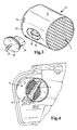
- Fig. 1 in a detailed perspective view of an air filter housing with an integrally formed elliptical air duct section, a radially inserted air mass flow sensor, and with a plugged into the air duct section plastic insert made of PBT,
- FIG. 2 in perspective exploded view of the arrangement FIG. 1 with details of a plastic grille comprising a grille and locking lugs,
- FIG. 3 in a perspective view, a variant of the arrangement according to the Figures 1 and 2 with air mass flow sensor integrated in the plastic insert,
- FIG. 4 the arrangement after FIG. 3 in the assembled state.
- Fig. 1 shows a perspective detail view of part of an air filter system of a motor vehicle drive motor.
- the air filter system is provided for supplying the drive motor with combustion air and includes an air cleaner housing 1, in which a drawing not shown air filter is arranged for filtering the combustion air flow.
- the air filter housing 1 On its clean air side, the air filter housing 1 comprises a housing part 2, which is injection molded from moisture-sensitive plastic, here polyamide (PA).
- PA polyamide
- the circumferential channel wall 5 and the housing part 2 are therefore made of the same plastic, here PA.
- a Luftleitgitter 7 and downstream of an air mass flow sensor 4 are arranged, wherein the air mass flow sensor 4 is formed in the embodiment shown as Heissfileinuftmassen- (HFM) sensor.
- HFM Heissfileinuftmassen-
- other types of air mass flow sensor 4 may be useful.
- the flow cross section of the air duct section 3 is elliptical and remains constant relative to the flow direction indicated by an arrow 17 in the area of the air mass flow sensor 4.
- a cross-sectional profile narrowing in the flow direction may also be expedient, which leads to an acceleration and thus to an improved laminar design of the flow around in the region of the air mass flow sensor 4.
- the air grille 7 also contributes to a laminar flow formation and thus the accuracy of measurement of the air mass flow sensor 4 arranged downstream thereof.
- the duct wall 5 of the air duct section 3 is lined on the inside by means of a plastic insert 6 of moisture-insensitive plastic in the region of the air mass flow sensor 4.
- the moisture-insensitive plastic of the plastic insert 6 preferably consists at least predominantly of polybutylene terephthalate (PBT) and in the exemplary embodiment shown is a glass fiber-reinforced PBT, here PBT-GF30 with 30% glass fiber content.
- PBT polybutylene terephthalate
- a circumferential wall 13 of the plastic insert 6 rests flat against the inside of the channel wall 5 and extends with respect to the flow direction indicated by the arrow 17 from a location upstream of the air mass flow sensor 4 to a location downstream of the air mass flow sensor 4.
- the air mass flow sensor 4 is thus based on the Flow direction in a region of the air duct section 3, the channel wall 5 is completely lined by the peripheral wall 13 of the plastic insert 6.
- the inside of the peripheral wall 13 is aerodynamically smooth executed without shocks, edges or the like, so that its limited around her intake air flow is free of turbulence or other disturbances.
- the flow path in the air duct section 3 is therefore predetermined by the enveloping, the flow cross section surrounding peripheral wall 13 of the plastic insert 6.
- moisture-insensitive plastic undergoes the plastic insert 6 no moisture-related dimensional changes, whereby the geometric flow in the air duct section 3 is substantially free of moisture-related influences.
- the measurement result of the air mass flow sensor 4 is also substantially unaffected by moisture-related dimensional changes.
- Fig. 2 shows in perspective exploded view of the arrangement Fig. 1 with details of the design of the plastic insert 6 and the assembly of the air mass flow sensor 4.
- the plastic insert 6 includes the elliptical flow cross-section enclosing peripheral wall 13, on the outside of axially extending ribs 24 are formed.
- the free flow cross section spanning air grille 7 is integrally formed of the same material and material.
- a few locking lugs 16 are formed on the outside of the peripheral wall.
- the circumferential wall 13 is provided centrally in the axial direction with an opening 14, which is arranged in the region of the large semiaxis of the elliptical cross-sectional contour.
- each a detent opening 15 are provided for each locking lug 16 of the plastic insert, wherein the locking lugs 16 when inserting the plastic insert 6 snap into the detent openings 15 and thus fix the plastic insert 6 in the air duct section 3 axially.
- An orientation of the plastic insert 6 relative to the air duct section 3 in the direction of rotation is predetermined by the elliptical cross-sectional shape of both components. But it may also be appropriate a different cross-sectional shape.
- the channel wall 5 of the air duct section 3 is provided with a mounting stub 8 for the air mass flow sensor 4, wherein the attachment stub 8 encloses an opening 9 penetrating the duct wall 5.
- the air mass flow sensor 4 is inserted radially from the outside through the opening 9 and the opening 14 into the free flow cross section of the air duct section 3, wherein the free end of the Air mass flow sensor 4 as shown by Fig. 1 comes to lie approximately in the middle in the free flow cross section.
- this has an outer flange 11 which rests on the end face of the attachment piece 8.
- An attachment is made by two screws 12, which are screwed through the flange 11 into screw receptacles 10 of the attachment piece 8.
- Fig. 1 In assembled state as shown Fig. 1 is the flange 11 on the outside of the channel wall 5 and there carries a plug contact 18 for receiving a in the 3 and 4 Plug shown 19 for the electrical or metrological connection of the air mass flow sensor 4 to the engine control.
- Fig. 3 shows in perspective view a variant of the plastic insert 6 after the Fig. 1 and 2 , wherein the plastic insert 6 after Fig. 3 in the assembled state in the perspective view Fig. 4 is shown.
- the arrangement after the 3 and 4 agrees in their features and reference numbers, unless otherwise described below, with those according to the Fig. 1 and 2 match.
- the free flow cross-section of the air duct section 3 has a circular cross section, for which reason the duct wall 5 of the air duct section 3 and the peripheral wall 13 of the plastic insert 6 are cylindrical. But it can also be appropriate in the flow direction narrowing, such as conical design. For a correct position in the direction of rotation assembly of the plastic insert.
Landscapes
- Engineering & Computer Science (AREA)
- Chemical & Material Sciences (AREA)
- Combustion & Propulsion (AREA)
- Mechanical Engineering (AREA)
- General Engineering & Computer Science (AREA)
- Physics & Mathematics (AREA)
- Fluid Mechanics (AREA)
- Analytical Chemistry (AREA)
- Measuring Volume Flow (AREA)
Applications Claiming Priority (1)
| Application Number | Priority Date | Filing Date | Title |
|---|---|---|---|
| DE202008010058U DE202008010058U1 (de) | 2008-07-25 | 2008-07-25 | Luftfiltersystem eines Kraftfahrzeuges |
Publications (2)
| Publication Number | Publication Date |
|---|---|
| EP2154358A1 true EP2154358A1 (fr) | 2010-02-17 |
| EP2154358B1 EP2154358B1 (fr) | 2012-08-29 |
Family
ID=41010052
Family Applications (1)
| Application Number | Title | Priority Date | Filing Date |
|---|---|---|---|
| EP09165938A Not-in-force EP2154358B1 (fr) | 2008-07-25 | 2009-07-21 | Filtre d'air pour un véhicule automobile |
Country Status (3)
| Country | Link |
|---|---|
| US (1) | US8241413B2 (fr) |
| EP (1) | EP2154358B1 (fr) |
| DE (1) | DE202008010058U1 (fr) |
Cited By (4)
| Publication number | Priority date | Publication date | Assignee | Title |
|---|---|---|---|---|
| DE102012000565B3 (de) * | 2012-01-16 | 2013-06-06 | Mann+Hummel Gmbh | Luftfiltersystem einer Brennkraftmaschine |
| CN105214488A (zh) * | 2015-11-14 | 2016-01-06 | 无锡清杨机械制造有限公司 | 一种汽车除异味方法 |
| CN105289287A (zh) * | 2015-11-14 | 2016-02-03 | 无锡清杨机械制造有限公司 | 一种汽车除异味方法 |
| RU2772440C1 (ru) * | 2021-08-31 | 2022-05-20 | Федеральное государственное бюджетное образовательное учреждение высшего образования "Ярославский государственный технический университет" ФГБОУВО "ЯГТУ" | Комбинированный воздушный фильтр |
Families Citing this family (17)
| Publication number | Priority date | Publication date | Assignee | Title |
|---|---|---|---|---|
| DE102009048684B4 (de) * | 2009-10-07 | 2019-01-10 | Audi Ag | Bausatz mit einer Luftfilterpatrone und einem Restriktorelement |
| US8807118B2 (en) * | 2010-06-17 | 2014-08-19 | Cummins Filtration Ip Inc. | Integrated idealized inlet for engine air induction system |
| USD681678S1 (en) * | 2011-08-08 | 2013-05-07 | Marco Antonio Portillo | Circular in-line air filter |
| CN107081026B (zh) | 2011-10-31 | 2019-07-23 | 唐纳森公司 | 空气过滤器组件 |
| DE102012005732A1 (de) * | 2012-03-23 | 2013-09-26 | Mann + Hummel Gmbh | Flachfilterelement und Luftfilter |
| DE102012005731B4 (de) * | 2012-03-23 | 2017-07-06 | Mann + Hummel Gmbh | Luftfilter und Filterelement eines Luftfilters |
| DE102012005734A1 (de) * | 2012-03-23 | 2013-09-26 | Mann + Hummel Gmbh | Flachfilterelement, Filtergehäuse und Luftfilter |
| US9440175B2 (en) * | 2012-11-01 | 2016-09-13 | Advanced Flow Engineering, Inc. | Interface air filter and assembly |
| DE102013011455B4 (de) * | 2013-07-10 | 2022-04-28 | Mann + Hummel Gmbh | Filtersystem mit einer Reinseite und einer Rohseite und ein Filtergehäuse für ein Filtersystem |
| DE102013218217A1 (de) * | 2013-09-11 | 2015-03-26 | Mahle International Gmbh | Luftfilter |
| US9689357B2 (en) * | 2013-11-15 | 2017-06-27 | Quirt Evan Crawford | Method and apparatus for improving engine performance |
| DE102014014398A1 (de) * | 2014-10-02 | 2016-04-07 | Mann + Hummel Gmbh | Fluidführungssystem |
| CN105289154A (zh) * | 2015-11-14 | 2016-02-03 | 无锡清杨机械制造有限公司 | 一种汽车除异味方法 |
| DE102017002086A1 (de) | 2017-03-03 | 2018-09-06 | Man Truck & Bus Ag | Kraftfahrzeug-Rohrleitung mit einem Mischelement aus einer Drahtstruktur |
| USD902255S1 (en) * | 2019-07-31 | 2020-11-17 | PRL Motorsports LLC | Intake system |
| WO2023196352A1 (fr) * | 2022-04-06 | 2023-10-12 | Daimler Truck North America Llc | Appareils d'admission d'air de véhicule et procédés associés |
| FR3135759A1 (fr) | 2022-05-20 | 2023-11-24 | Sogefi Filtration | Filtre à air moteur pourvu d’un dispositif à capteur et méthode de connexion du dispositif à capteur en sortie du filtre |
Citations (2)
| Publication number | Priority date | Publication date | Assignee | Title |
|---|---|---|---|---|
| EP1052489A2 (fr) * | 1999-05-12 | 2000-11-15 | Siemens Canada limited | Arrangement de fixation d'un capteur par pression |
| EP1193389A1 (fr) * | 2000-09-29 | 2002-04-03 | Siemens Canada Limited | Système de purification d'air |
Family Cites Families (19)
| Publication number | Priority date | Publication date | Assignee | Title |
|---|---|---|---|---|
| DE4340882A1 (de) * | 1993-12-01 | 1995-06-08 | Bosch Gmbh Robert | Vorrichtung zur Messung der Masse eines strömenden Mediums |
| DE4443812A1 (de) * | 1994-12-09 | 1996-06-13 | Bosch Gmbh Robert | Verfahren zur Bildung eines Signals bezüglich der Temperatur der von einer Brennkraftmaschine angesaugten Luft |
| DE19517676B4 (de) * | 1995-05-13 | 2008-01-31 | Robert Bosch Gmbh | Drucksensor für eine Brennkraftmaschine mit einem Ansaugrohr |
| JP3169808B2 (ja) * | 1995-09-29 | 2001-05-28 | 株式会社日立製作所 | 空気流量測定装置およびエアクリーナケース |
| JP3285513B2 (ja) * | 1997-05-28 | 2002-05-27 | 三菱電機株式会社 | 感熱式流量センサおよび内燃機関の吸気装置 |
| US5853439A (en) * | 1997-06-27 | 1998-12-29 | Donaldson Company, Inc. | Aerosol separator and method |
| DE19815658A1 (de) * | 1998-04-08 | 1999-10-14 | Bosch Gmbh Robert | Vorrichtung zum Messen der Masse eines strömenden Mediums |
| DE19942502A1 (de) * | 1999-09-07 | 2001-03-08 | Bosch Gmbh Robert | Vorrichtung zur Messung von zumindest einem Parameter eines in einer Leitung strömenden Mediums |
| US20020088214A1 (en) * | 2001-01-05 | 2002-07-11 | Sherwood Walter J. | Filter system for small engines |
| US7416580B2 (en) * | 2001-04-11 | 2008-08-26 | Donaldsom Company, Inc. | Filter assemblies and systems for intake air for fuel cells |
| DE10208872C1 (de) * | 2002-03-01 | 2003-08-07 | Emitec Emissionstechnologie | Verfahren zum Herstellen eines Wabenkörpers, insbesondere für einen Katalysator-Trägerkörper in Abgasreinigungsanlagen von Brennkraftmaschinen, mit einem Flanschstück zur Aufnahme für einen Messfühler und entsprechend hergestellter Wabenkörper |
| US7083860B2 (en) * | 2002-08-16 | 2006-08-01 | Emitec Gesellschaft Fuer Emissionstechnologie Mbh | Metallic honeycomb body having at least partially perforated sheet-metal layers |
| EP1422396B1 (fr) * | 2002-11-20 | 2006-09-27 | J. Eberspächer GmbH & Co. KG | catalyseur à lits multiples |
| DE10300408A1 (de) * | 2003-01-09 | 2004-07-22 | Emitec Gesellschaft Für Emissionstechnologie Mbh | Verfahren zur Behandlung eines Fluids und Wabenkörper |
| US7418815B2 (en) * | 2004-07-30 | 2008-09-02 | Caterpillar Inc. | Particulate trap with electrostatic precipitator |
| DE102004063546A1 (de) * | 2004-12-30 | 2006-07-13 | Emitec Gesellschaft Für Emissionstechnologie Mbh | Wabenkörper mit zumindest teilweise keramischer Wabenstruktur und Aufnahme für Messfühler |
| DE102005055479A1 (de) * | 2005-11-18 | 2007-05-31 | Mahle International Gmbh | Luftfiltergehäuse |
| US7794672B2 (en) * | 2007-01-11 | 2010-09-14 | Automotive Components Holdings, Llc | Catalytic converter with sensor cavity |
| US8887495B2 (en) * | 2009-07-14 | 2014-11-18 | GM Global Technology Operations LLC | Ash filter, exhaust gas treatment system incorporating the same and method of using the same |
-
2008
- 2008-07-25 DE DE202008010058U patent/DE202008010058U1/de not_active Expired - Lifetime
-
2009
- 2009-07-21 EP EP09165938A patent/EP2154358B1/fr not_active Not-in-force
- 2009-07-23 US US12/507,882 patent/US8241413B2/en not_active Expired - Fee Related
Patent Citations (2)
| Publication number | Priority date | Publication date | Assignee | Title |
|---|---|---|---|---|
| EP1052489A2 (fr) * | 1999-05-12 | 2000-11-15 | Siemens Canada limited | Arrangement de fixation d'un capteur par pression |
| EP1193389A1 (fr) * | 2000-09-29 | 2002-04-03 | Siemens Canada Limited | Système de purification d'air |
Cited By (4)
| Publication number | Priority date | Publication date | Assignee | Title |
|---|---|---|---|---|
| DE102012000565B3 (de) * | 2012-01-16 | 2013-06-06 | Mann+Hummel Gmbh | Luftfiltersystem einer Brennkraftmaschine |
| CN105214488A (zh) * | 2015-11-14 | 2016-01-06 | 无锡清杨机械制造有限公司 | 一种汽车除异味方法 |
| CN105289287A (zh) * | 2015-11-14 | 2016-02-03 | 无锡清杨机械制造有限公司 | 一种汽车除异味方法 |
| RU2772440C1 (ru) * | 2021-08-31 | 2022-05-20 | Федеральное государственное бюджетное образовательное учреждение высшего образования "Ярославский государственный технический университет" ФГБОУВО "ЯГТУ" | Комбинированный воздушный фильтр |
Also Published As
| Publication number | Publication date |
|---|---|
| DE202008010058U1 (de) | 2009-12-03 |
| US8241413B2 (en) | 2012-08-14 |
| EP2154358B1 (fr) | 2012-08-29 |
| US20100018400A1 (en) | 2010-01-28 |
Similar Documents
| Publication | Publication Date | Title |
|---|---|---|
| EP2154358B1 (fr) | Filtre d'air pour un véhicule automobile | |
| EP3362801B1 (fr) | Module de détection pour un capteur de courant, et procédé de montage d'un module de détection | |
| DE102004035511B4 (de) | Elektrisch gesteuertes Drosselgerät mit einem plattenförmigen inneren Verbindungselement | |
| DE19534887A1 (de) | Temperaturfühler | |
| EP1969380A1 (fr) | Unite a aimant destinee a etre fixee sur un arbre | |
| WO1995006807A1 (fr) | Dispositif d'etranglement | |
| DE102014226483A1 (de) | Positionserfassungseinrichtung | |
| EP2504557B1 (fr) | Dispositif de clapet et dispositif d'alimentation | |
| DE102010018724A1 (de) | Induktiver Drehwinkelsensor | |
| DE19522648A1 (de) | Thermisches Strömungsmeßgerät mit geringer Turbulenz in der Fluidströmung | |
| EP2686644B1 (fr) | Dispositif servant à appréhender au moins une propriété d'un milieu fluide | |
| DE102016124370A1 (de) | Sensorvorrichtung sowie Verfahren zum Zusammenbau einer Sensorvorrichtung | |
| DE112010004781B4 (de) | Filtersystem und filterelement zur filtrierung von fluiden | |
| DE102009046392A1 (de) | Sensoranordnung für ein Fahrzeug und korrespondierendes Verfahren zur Herstellung einer solchen Sensoranordnung | |
| EP1298299B1 (fr) | Dispositif d'étranglement avec des éléments de boîtiers échangeables | |
| DE10321004A1 (de) | Luftstromgeschwindigkeits-Messvorrichtung | |
| DE4401585A1 (de) | Drosseleinrichtung | |
| DE10048937A1 (de) | Drosselklappenstelleinheit | |
| DE102009016298A1 (de) | Wegmesssystem für Kupplungsausrücksysteme | |
| DE102014202425A1 (de) | Planetengetriebe mit einem integrierten Geberelement für eine Drehzahlmessung | |
| DE19825727A1 (de) | Drosselklappenstutzen | |
| DE102011016627A1 (de) | Messeinrichtung und Kraftfahrzeuglenkung mit einer solchen | |
| EP3208454A1 (fr) | Bride étanche de vilebrequins | |
| EP1714018A1 (fr) | Dispositif etrangleur | |
| EP4061505B1 (fr) | Filtre à air comprenant une sortie d'air primaire et une sortie d'air secondaire |
Legal Events
| Date | Code | Title | Description |
|---|---|---|---|
| PUAI | Public reference made under article 153(3) epc to a published international application that has entered the european phase |
Free format text: ORIGINAL CODE: 0009012 |
|
| AK | Designated contracting states |
Kind code of ref document: A1 Designated state(s): AT BE BG CH CY CZ DE DK EE ES FI FR GB GR HR HU IE IS IT LI LT LU LV MC MK MT NL NO PL PT RO SE SI SK SM TR |
|
| 17P | Request for examination filed |
Effective date: 20100409 |
|
| 17Q | First examination report despatched |
Effective date: 20100512 |
|
| REG | Reference to a national code |
Ref country code: DE Ref legal event code: R079 Ref document number: 502009004516 Country of ref document: DE Free format text: PREVIOUS MAIN CLASS: F02M0035024000 Ipc: F02M0035100000 |
|
| GRAP | Despatch of communication of intention to grant a patent |
Free format text: ORIGINAL CODE: EPIDOSNIGR1 |
|
| RIC1 | Information provided on ipc code assigned before grant |
Ipc: F02M 35/02 20060101ALI20120208BHEP Ipc: F02M 35/10 20060101AFI20120208BHEP Ipc: F02M 35/024 20060101ALI20120208BHEP |
|
| GRAS | Grant fee paid |
Free format text: ORIGINAL CODE: EPIDOSNIGR3 |
|
| GRAA | (expected) grant |
Free format text: ORIGINAL CODE: 0009210 |
|
| RIN1 | Information on inventor provided before grant (corrected) |
Inventor name: DIRNBERGER, TIMO |
|
| AK | Designated contracting states |
Kind code of ref document: B1 Designated state(s): AT BE BG CH CY CZ DE DK EE ES FI FR GB GR HR HU IE IS IT LI LT LU LV MC MK MT NL NO PL PT RO SE SI SK SM TR |
|
| REG | Reference to a national code |
Ref country code: GB Ref legal event code: FG4D Free format text: NOT ENGLISH |
|
| REG | Reference to a national code |
Ref country code: CH Ref legal event code: EP |
|
| REG | Reference to a national code |
Ref country code: AT Ref legal event code: REF Ref document number: 573226 Country of ref document: AT Kind code of ref document: T Effective date: 20120915 |
|
| REG | Reference to a national code |
Ref country code: IE Ref legal event code: FG4D Free format text: LANGUAGE OF EP DOCUMENT: GERMAN |
|
| REG | Reference to a national code |
Ref country code: DE Ref legal event code: R096 Ref document number: 502009004516 Country of ref document: DE Effective date: 20121018 |
|
| REG | Reference to a national code |
Ref country code: NL Ref legal event code: VDEP Effective date: 20120829 |
|
| REG | Reference to a national code |
Ref country code: LT Ref legal event code: MG4D Effective date: 20120829 |
|
| PG25 | Lapsed in a contracting state [announced via postgrant information from national office to epo] |
Ref country code: HR Free format text: LAPSE BECAUSE OF FAILURE TO SUBMIT A TRANSLATION OF THE DESCRIPTION OR TO PAY THE FEE WITHIN THE PRESCRIBED TIME-LIMIT Effective date: 20120829 Ref country code: CY Free format text: LAPSE BECAUSE OF FAILURE TO SUBMIT A TRANSLATION OF THE DESCRIPTION OR TO PAY THE FEE WITHIN THE PRESCRIBED TIME-LIMIT Effective date: 20120829 Ref country code: FI Free format text: LAPSE BECAUSE OF FAILURE TO SUBMIT A TRANSLATION OF THE DESCRIPTION OR TO PAY THE FEE WITHIN THE PRESCRIBED TIME-LIMIT Effective date: 20120829 Ref country code: LT Free format text: LAPSE BECAUSE OF FAILURE TO SUBMIT A TRANSLATION OF THE DESCRIPTION OR TO PAY THE FEE WITHIN THE PRESCRIBED TIME-LIMIT Effective date: 20120829 Ref country code: IS Free format text: LAPSE BECAUSE OF FAILURE TO SUBMIT A TRANSLATION OF THE DESCRIPTION OR TO PAY THE FEE WITHIN THE PRESCRIBED TIME-LIMIT Effective date: 20121229 Ref country code: NO Free format text: LAPSE BECAUSE OF FAILURE TO SUBMIT A TRANSLATION OF THE DESCRIPTION OR TO PAY THE FEE WITHIN THE PRESCRIBED TIME-LIMIT Effective date: 20121129 |
|
| PG25 | Lapsed in a contracting state [announced via postgrant information from national office to epo] |
Ref country code: SE Free format text: LAPSE BECAUSE OF FAILURE TO SUBMIT A TRANSLATION OF THE DESCRIPTION OR TO PAY THE FEE WITHIN THE PRESCRIBED TIME-LIMIT Effective date: 20120829 Ref country code: PT Free format text: LAPSE BECAUSE OF FAILURE TO SUBMIT A TRANSLATION OF THE DESCRIPTION OR TO PAY THE FEE WITHIN THE PRESCRIBED TIME-LIMIT Effective date: 20121231 Ref country code: GR Free format text: LAPSE BECAUSE OF FAILURE TO SUBMIT A TRANSLATION OF THE DESCRIPTION OR TO PAY THE FEE WITHIN THE PRESCRIBED TIME-LIMIT Effective date: 20121130 Ref country code: SI Free format text: LAPSE BECAUSE OF FAILURE TO SUBMIT A TRANSLATION OF THE DESCRIPTION OR TO PAY THE FEE WITHIN THE PRESCRIBED TIME-LIMIT Effective date: 20120829 Ref country code: LV Free format text: LAPSE BECAUSE OF FAILURE TO SUBMIT A TRANSLATION OF THE DESCRIPTION OR TO PAY THE FEE WITHIN THE PRESCRIBED TIME-LIMIT Effective date: 20120829 |
|
| PG25 | Lapsed in a contracting state [announced via postgrant information from national office to epo] |
Ref country code: RO Free format text: LAPSE BECAUSE OF FAILURE TO SUBMIT A TRANSLATION OF THE DESCRIPTION OR TO PAY THE FEE WITHIN THE PRESCRIBED TIME-LIMIT Effective date: 20120829 Ref country code: DK Free format text: LAPSE BECAUSE OF FAILURE TO SUBMIT A TRANSLATION OF THE DESCRIPTION OR TO PAY THE FEE WITHIN THE PRESCRIBED TIME-LIMIT Effective date: 20120829 Ref country code: CZ Free format text: LAPSE BECAUSE OF FAILURE TO SUBMIT A TRANSLATION OF THE DESCRIPTION OR TO PAY THE FEE WITHIN THE PRESCRIBED TIME-LIMIT Effective date: 20120829 Ref country code: EE Free format text: LAPSE BECAUSE OF FAILURE TO SUBMIT A TRANSLATION OF THE DESCRIPTION OR TO PAY THE FEE WITHIN THE PRESCRIBED TIME-LIMIT Effective date: 20120829 Ref country code: ES Free format text: LAPSE BECAUSE OF FAILURE TO SUBMIT A TRANSLATION OF THE DESCRIPTION OR TO PAY THE FEE WITHIN THE PRESCRIBED TIME-LIMIT Effective date: 20121210 Ref country code: NL Free format text: LAPSE BECAUSE OF FAILURE TO SUBMIT A TRANSLATION OF THE DESCRIPTION OR TO PAY THE FEE WITHIN THE PRESCRIBED TIME-LIMIT Effective date: 20120829 |
|
| PG25 | Lapsed in a contracting state [announced via postgrant information from national office to epo] |
Ref country code: SK Free format text: LAPSE BECAUSE OF FAILURE TO SUBMIT A TRANSLATION OF THE DESCRIPTION OR TO PAY THE FEE WITHIN THE PRESCRIBED TIME-LIMIT Effective date: 20120829 Ref country code: PL Free format text: LAPSE BECAUSE OF FAILURE TO SUBMIT A TRANSLATION OF THE DESCRIPTION OR TO PAY THE FEE WITHIN THE PRESCRIBED TIME-LIMIT Effective date: 20120829 Ref country code: IT Free format text: LAPSE BECAUSE OF FAILURE TO SUBMIT A TRANSLATION OF THE DESCRIPTION OR TO PAY THE FEE WITHIN THE PRESCRIBED TIME-LIMIT Effective date: 20120829 |
|
| PLBE | No opposition filed within time limit |
Free format text: ORIGINAL CODE: 0009261 |
|
| STAA | Information on the status of an ep patent application or granted ep patent |
Free format text: STATUS: NO OPPOSITION FILED WITHIN TIME LIMIT |
|
| PG25 | Lapsed in a contracting state [announced via postgrant information from national office to epo] |
Ref country code: BG Free format text: LAPSE BECAUSE OF FAILURE TO SUBMIT A TRANSLATION OF THE DESCRIPTION OR TO PAY THE FEE WITHIN THE PRESCRIBED TIME-LIMIT Effective date: 20121129 |
|
| 26N | No opposition filed |
Effective date: 20130530 |
|
| REG | Reference to a national code |
Ref country code: DE Ref legal event code: R097 Ref document number: 502009004516 Country of ref document: DE Effective date: 20130530 |
|
| BERE | Be: lapsed |
Owner name: MANN+HUMMEL G.M.B.H. Effective date: 20130731 |
|
| PG25 | Lapsed in a contracting state [announced via postgrant information from national office to epo] |
Ref country code: MC Free format text: LAPSE BECAUSE OF FAILURE TO SUBMIT A TRANSLATION OF THE DESCRIPTION OR TO PAY THE FEE WITHIN THE PRESCRIBED TIME-LIMIT Effective date: 20120829 |
|
| REG | Reference to a national code |
Ref country code: CH Ref legal event code: PL |
|
| GBPC | Gb: european patent ceased through non-payment of renewal fee |
Effective date: 20130721 |
|
| REG | Reference to a national code |
Ref country code: IE Ref legal event code: MM4A |
|
| PG25 | Lapsed in a contracting state [announced via postgrant information from national office to epo] |
Ref country code: CH Free format text: LAPSE BECAUSE OF NON-PAYMENT OF DUE FEES Effective date: 20130731 Ref country code: BE Free format text: LAPSE BECAUSE OF NON-PAYMENT OF DUE FEES Effective date: 20130731 Ref country code: LI Free format text: LAPSE BECAUSE OF NON-PAYMENT OF DUE FEES Effective date: 20130731 Ref country code: GB Free format text: LAPSE BECAUSE OF NON-PAYMENT OF DUE FEES Effective date: 20130721 |
|
| PG25 | Lapsed in a contracting state [announced via postgrant information from national office to epo] |
Ref country code: IE Free format text: LAPSE BECAUSE OF NON-PAYMENT OF DUE FEES Effective date: 20130721 |
|
| PG25 | Lapsed in a contracting state [announced via postgrant information from national office to epo] |
Ref country code: SM Free format text: LAPSE BECAUSE OF FAILURE TO SUBMIT A TRANSLATION OF THE DESCRIPTION OR TO PAY THE FEE WITHIN THE PRESCRIBED TIME-LIMIT Effective date: 20120829 |
|
| PG25 | Lapsed in a contracting state [announced via postgrant information from national office to epo] |
Ref country code: MT Free format text: LAPSE BECAUSE OF FAILURE TO SUBMIT A TRANSLATION OF THE DESCRIPTION OR TO PAY THE FEE WITHIN THE PRESCRIBED TIME-LIMIT Effective date: 20120829 Ref country code: TR Free format text: LAPSE BECAUSE OF FAILURE TO SUBMIT A TRANSLATION OF THE DESCRIPTION OR TO PAY THE FEE WITHIN THE PRESCRIBED TIME-LIMIT Effective date: 20120829 |
|
| PG25 | Lapsed in a contracting state [announced via postgrant information from national office to epo] |
Ref country code: HU Free format text: LAPSE BECAUSE OF FAILURE TO SUBMIT A TRANSLATION OF THE DESCRIPTION OR TO PAY THE FEE WITHIN THE PRESCRIBED TIME-LIMIT; INVALID AB INITIO Effective date: 20090721 Ref country code: MK Free format text: LAPSE BECAUSE OF FAILURE TO SUBMIT A TRANSLATION OF THE DESCRIPTION OR TO PAY THE FEE WITHIN THE PRESCRIBED TIME-LIMIT Effective date: 20120829 Ref country code: LU Free format text: LAPSE BECAUSE OF NON-PAYMENT OF DUE FEES Effective date: 20130721 |
|
| REG | Reference to a national code |
Ref country code: AT Ref legal event code: MM01 Ref document number: 573226 Country of ref document: AT Kind code of ref document: T Effective date: 20140721 |
|
| PG25 | Lapsed in a contracting state [announced via postgrant information from national office to epo] |
Ref country code: AT Free format text: LAPSE BECAUSE OF NON-PAYMENT OF DUE FEES Effective date: 20140721 |
|
| REG | Reference to a national code |
Ref country code: FR Ref legal event code: PLFP Year of fee payment: 8 |
|
| REG | Reference to a national code |
Ref country code: FR Ref legal event code: PLFP Year of fee payment: 9 |
|
| REG | Reference to a national code |
Ref country code: DE Ref legal event code: R081 Ref document number: 502009004516 Country of ref document: DE Owner name: MANN+HUMMEL GMBH, DE Free format text: FORMER OWNER: MANN + HUMMEL GMBH, 71638 LUDWIGSBURG, DE |
|
| REG | Reference to a national code |
Ref country code: FR Ref legal event code: PLFP Year of fee payment: 10 |
|
| PGFP | Annual fee paid to national office [announced via postgrant information from national office to epo] |
Ref country code: FR Payment date: 20230725 Year of fee payment: 15 Ref country code: DE Payment date: 20230719 Year of fee payment: 15 |
|
| REG | Reference to a national code |
Ref country code: DE Ref legal event code: R119 Ref document number: 502009004516 Country of ref document: DE |
|
| PG25 | Lapsed in a contracting state [announced via postgrant information from national office to epo] |
Ref country code: DE Free format text: LAPSE BECAUSE OF NON-PAYMENT OF DUE FEES Effective date: 20250201 |
|
| PG25 | Lapsed in a contracting state [announced via postgrant information from national office to epo] |
Ref country code: FR Free format text: LAPSE BECAUSE OF NON-PAYMENT OF DUE FEES Effective date: 20240731 |