EP3208454A1 - Bride étanche de vilebrequins - Google Patents
Bride étanche de vilebrequins Download PDFInfo
- Publication number
- EP3208454A1 EP3208454A1 EP16002339.6A EP16002339A EP3208454A1 EP 3208454 A1 EP3208454 A1 EP 3208454A1 EP 16002339 A EP16002339 A EP 16002339A EP 3208454 A1 EP3208454 A1 EP 3208454A1
- Authority
- EP
- European Patent Office
- Prior art keywords
- sealing flange
- sensor
- carrier
- flange according
- electronic assembly
- Prior art date
- Legal status (The legal status is an assumption and is not a legal conclusion. Google has not performed a legal analysis and makes no representation as to the accuracy of the status listed.)
- Granted
Links
Images

Classifications
-
- F—MECHANICAL ENGINEERING; LIGHTING; HEATING; WEAPONS; BLASTING
- F16—ENGINEERING ELEMENTS AND UNITS; GENERAL MEASURES FOR PRODUCING AND MAINTAINING EFFECTIVE FUNCTIONING OF MACHINES OR INSTALLATIONS; THERMAL INSULATION IN GENERAL
- F16J—PISTONS; CYLINDERS; SEALINGS
- F16J15/00—Sealings
- F16J15/16—Sealings between relatively-moving surfaces
- F16J15/32—Sealings between relatively-moving surfaces with elastic sealings, e.g. O-rings
- F16J15/3248—Sealings between relatively-moving surfaces with elastic sealings, e.g. O-rings provided with casings or supports
- F16J15/3252—Sealings between relatively-moving surfaces with elastic sealings, e.g. O-rings provided with casings or supports with rigid casings or supports
-
- F—MECHANICAL ENGINEERING; LIGHTING; HEATING; WEAPONS; BLASTING
- F16—ENGINEERING ELEMENTS AND UNITS; GENERAL MEASURES FOR PRODUCING AND MAINTAINING EFFECTIVE FUNCTIONING OF MACHINES OR INSTALLATIONS; THERMAL INSULATION IN GENERAL
- F16C—SHAFTS; FLEXIBLE SHAFTS; ELEMENTS OR CRANKSHAFT MECHANISMS; ROTARY BODIES OTHER THAN GEARING ELEMENTS; BEARINGS
- F16C35/00—Rigid support of bearing units; Housings, e.g. caps, covers
- F16C35/02—Rigid support of bearing units; Housings, e.g. caps, covers in the case of sliding-contact bearings
-
- F—MECHANICAL ENGINEERING; LIGHTING; HEATING; WEAPONS; BLASTING
- F02—COMBUSTION ENGINES; HOT-GAS OR COMBUSTION-PRODUCT ENGINE PLANTS
- F02F—CYLINDERS, PISTONS OR CASINGS, FOR COMBUSTION ENGINES; ARRANGEMENTS OF SEALINGS IN COMBUSTION ENGINES
- F02F7/00—Casings, e.g. crankcases
- F02F7/0043—Arrangements of mechanical drive elements
-
- F—MECHANICAL ENGINEERING; LIGHTING; HEATING; WEAPONS; BLASTING
- F02—COMBUSTION ENGINES; HOT-GAS OR COMBUSTION-PRODUCT ENGINE PLANTS
- F02P—IGNITION, OTHER THAN COMPRESSION IGNITION, FOR INTERNAL-COMBUSTION ENGINES; TESTING OF IGNITION TIMING IN COMPRESSION-IGNITION ENGINES
- F02P7/00—Arrangements of distributors, circuit-makers or -breakers, e.g. of distributor and circuit-breaker combinations or pick-up devices
- F02P7/06—Arrangements of distributors, circuit-makers or -breakers, e.g. of distributor and circuit-breaker combinations or pick-up devices of circuit-makers or -breakers, or pick-up devices adapted to sense particular points of the timing cycle
- F02P7/067—Electromagnetic pick-up devices, e.g. providing induced current in a coil
- F02P7/07—Hall-effect pick-up devices
-
- F—MECHANICAL ENGINEERING; LIGHTING; HEATING; WEAPONS; BLASTING
- F16—ENGINEERING ELEMENTS AND UNITS; GENERAL MEASURES FOR PRODUCING AND MAINTAINING EFFECTIVE FUNCTIONING OF MACHINES OR INSTALLATIONS; THERMAL INSULATION IN GENERAL
- F16C—SHAFTS; FLEXIBLE SHAFTS; ELEMENTS OR CRANKSHAFT MECHANISMS; ROTARY BODIES OTHER THAN GEARING ELEMENTS; BEARINGS
- F16C33/00—Parts of bearings; Special methods for making bearings or parts thereof
- F16C33/02—Parts of sliding-contact bearings
- F16C33/04—Brasses; Bushes; Linings
- F16C33/20—Sliding surface consisting mainly of plastics
- F16C33/201—Composition of the plastic
-
- F—MECHANICAL ENGINEERING; LIGHTING; HEATING; WEAPONS; BLASTING
- F16—ENGINEERING ELEMENTS AND UNITS; GENERAL MEASURES FOR PRODUCING AND MAINTAINING EFFECTIVE FUNCTIONING OF MACHINES OR INSTALLATIONS; THERMAL INSULATION IN GENERAL
- F16C—SHAFTS; FLEXIBLE SHAFTS; ELEMENTS OR CRANKSHAFT MECHANISMS; ROTARY BODIES OTHER THAN GEARING ELEMENTS; BEARINGS
- F16C33/00—Parts of bearings; Special methods for making bearings or parts thereof
- F16C33/72—Sealings
- F16C33/74—Sealings of sliding-contact bearings
-
- F—MECHANICAL ENGINEERING; LIGHTING; HEATING; WEAPONS; BLASTING
- F16—ENGINEERING ELEMENTS AND UNITS; GENERAL MEASURES FOR PRODUCING AND MAINTAINING EFFECTIVE FUNCTIONING OF MACHINES OR INSTALLATIONS; THERMAL INSULATION IN GENERAL
- F16C—SHAFTS; FLEXIBLE SHAFTS; ELEMENTS OR CRANKSHAFT MECHANISMS; ROTARY BODIES OTHER THAN GEARING ELEMENTS; BEARINGS
- F16C41/00—Other accessories, e.g. devices integrated in the bearing not relating to the bearing function as such
- F16C41/002—Conductive elements, e.g. to prevent static electricity
-
- F—MECHANICAL ENGINEERING; LIGHTING; HEATING; WEAPONS; BLASTING
- F16—ENGINEERING ELEMENTS AND UNITS; GENERAL MEASURES FOR PRODUCING AND MAINTAINING EFFECTIVE FUNCTIONING OF MACHINES OR INSTALLATIONS; THERMAL INSULATION IN GENERAL
- F16C—SHAFTS; FLEXIBLE SHAFTS; ELEMENTS OR CRANKSHAFT MECHANISMS; ROTARY BODIES OTHER THAN GEARING ELEMENTS; BEARINGS
- F16C9/00—Bearings for crankshafts or connecting-rods; Attachment of connecting-rods
- F16C9/02—Crankshaft bearings
-
- F—MECHANICAL ENGINEERING; LIGHTING; HEATING; WEAPONS; BLASTING
- F16—ENGINEERING ELEMENTS AND UNITS; GENERAL MEASURES FOR PRODUCING AND MAINTAINING EFFECTIVE FUNCTIONING OF MACHINES OR INSTALLATIONS; THERMAL INSULATION IN GENERAL
- F16J—PISTONS; CYLINDERS; SEALINGS
- F16J15/00—Sealings
- F16J15/16—Sealings between relatively-moving surfaces
- F16J15/32—Sealings between relatively-moving surfaces with elastic sealings, e.g. O-rings
- F16J15/3204—Sealings between relatively-moving surfaces with elastic sealings, e.g. O-rings with at least one lip
-
- F—MECHANICAL ENGINEERING; LIGHTING; HEATING; WEAPONS; BLASTING
- F16—ENGINEERING ELEMENTS AND UNITS; GENERAL MEASURES FOR PRODUCING AND MAINTAINING EFFECTIVE FUNCTIONING OF MACHINES OR INSTALLATIONS; THERMAL INSULATION IN GENERAL
- F16J—PISTONS; CYLINDERS; SEALINGS
- F16J15/00—Sealings
- F16J15/16—Sealings between relatively-moving surfaces
- F16J15/32—Sealings between relatively-moving surfaces with elastic sealings, e.g. O-rings
- F16J15/3248—Sealings between relatively-moving surfaces with elastic sealings, e.g. O-rings provided with casings or supports
- F16J15/3252—Sealings between relatively-moving surfaces with elastic sealings, e.g. O-rings provided with casings or supports with rigid casings or supports
- F16J15/3256—Sealings between relatively-moving surfaces with elastic sealings, e.g. O-rings provided with casings or supports with rigid casings or supports comprising two casing or support elements, one attached to each surface, e.g. cartridge or cassette seals
- F16J15/326—Sealings between relatively-moving surfaces with elastic sealings, e.g. O-rings provided with casings or supports with rigid casings or supports comprising two casing or support elements, one attached to each surface, e.g. cartridge or cassette seals with means for detecting or measuring relative rotation of the two elements
-
- F—MECHANICAL ENGINEERING; LIGHTING; HEATING; WEAPONS; BLASTING
- F16—ENGINEERING ELEMENTS AND UNITS; GENERAL MEASURES FOR PRODUCING AND MAINTAINING EFFECTIVE FUNCTIONING OF MACHINES OR INSTALLATIONS; THERMAL INSULATION IN GENERAL
- F16J—PISTONS; CYLINDERS; SEALINGS
- F16J15/00—Sealings
- F16J15/16—Sealings between relatively-moving surfaces
- F16J15/32—Sealings between relatively-moving surfaces with elastic sealings, e.g. O-rings
- F16J15/3296—Arrangements for monitoring the condition or operation of elastic sealings; Arrangements for control of elastic sealings, e.g. of their geometry or stiffness
-
- G—PHYSICS
- G01—MEASURING; TESTING
- G01P—MEASURING LINEAR OR ANGULAR SPEED, ACCELERATION, DECELERATION, OR SHOCK; INDICATING PRESENCE, ABSENCE, OR DIRECTION, OF MOVEMENT
- G01P1/00—Details of instruments
- G01P1/02—Housings
- G01P1/026—Housings for speed measuring devices, e.g. pulse generator
-
- G—PHYSICS
- G01—MEASURING; TESTING
- G01P—MEASURING LINEAR OR ANGULAR SPEED, ACCELERATION, DECELERATION, OR SHOCK; INDICATING PRESENCE, ABSENCE, OR DIRECTION, OF MOVEMENT
- G01P3/00—Measuring linear or angular speed; Measuring differences of linear or angular speeds
-
- G—PHYSICS
- G01—MEASURING; TESTING
- G01P—MEASURING LINEAR OR ANGULAR SPEED, ACCELERATION, DECELERATION, OR SHOCK; INDICATING PRESENCE, ABSENCE, OR DIRECTION, OF MOVEMENT
- G01P3/00—Measuring linear or angular speed; Measuring differences of linear or angular speeds
- G01P3/42—Devices characterised by the use of electric or magnetic means
- G01P3/44—Devices characterised by the use of electric or magnetic means for measuring angular speed
- G01P3/443—Devices characterised by the use of electric or magnetic means for measuring angular speed mounted in bearings
-
- G—PHYSICS
- G01—MEASURING; TESTING
- G01P—MEASURING LINEAR OR ANGULAR SPEED, ACCELERATION, DECELERATION, OR SHOCK; INDICATING PRESENCE, ABSENCE, OR DIRECTION, OF MOVEMENT
- G01P3/00—Measuring linear or angular speed; Measuring differences of linear or angular speeds
- G01P3/42—Devices characterised by the use of electric or magnetic means
- G01P3/44—Devices characterised by the use of electric or magnetic means for measuring angular speed
- G01P3/48—Devices characterised by the use of electric or magnetic means for measuring angular speed by measuring frequency of generated current or voltage
- G01P3/481—Devices characterised by the use of electric or magnetic means for measuring angular speed by measuring frequency of generated current or voltage of pulse signals
-
- F—MECHANICAL ENGINEERING; LIGHTING; HEATING; WEAPONS; BLASTING
- F02—COMBUSTION ENGINES; HOT-GAS OR COMBUSTION-PRODUCT ENGINE PLANTS
- F02F—CYLINDERS, PISTONS OR CASINGS, FOR COMBUSTION ENGINES; ARRANGEMENTS OF SEALINGS IN COMBUSTION ENGINES
- F02F11/00—Arrangements of sealings in combustion engines
-
- F—MECHANICAL ENGINEERING; LIGHTING; HEATING; WEAPONS; BLASTING
- F16—ENGINEERING ELEMENTS AND UNITS; GENERAL MEASURES FOR PRODUCING AND MAINTAINING EFFECTIVE FUNCTIONING OF MACHINES OR INSTALLATIONS; THERMAL INSULATION IN GENERAL
- F16C—SHAFTS; FLEXIBLE SHAFTS; ELEMENTS OR CRANKSHAFT MECHANISMS; ROTARY BODIES OTHER THAN GEARING ELEMENTS; BEARINGS
- F16C2326/00—Articles relating to transporting
- F16C2326/01—Parts of vehicles in general
- F16C2326/06—Drive shafts
Definitions
- the invention relates to a crankshaft sealing flange according to the preamble of claim 1.
- Crankshaft sealing flanges are used to seal crankshafts in motor vehicles.
- the sealing flanges are screwed to the corresponding crankcase. Through the passage of the support of the sealing flange extends the crankshaft, at the periphery of the dynamic seal sealingly.
- the sealing flange is provided with a sensor which cooperates with a non-rotatably mounted on the crankshaft sender wheel.
- the sensor is a separate assembly that is bolted to the carrier.
- a radial guide is provided on the carrier for the sensor, which is located in the one side surface of the sealing flange and extends into the inner wall of the carrier. When the sensor is mounted, a gap remains between it and the side wall of the guide extending outwardly from the inner wall of the carrier.
- the sensor Since the sensor is screwed to the carrier, it is costly to bring the sensor in an exact position relative to the sealing flange or the carrier, because when tightening the screw, it can not be avoided that the already tolerant position of the sensor radially, changes tangentially as well as axially.
- the sensor connection is sensitive to vibration and vibration, which can affect the accuracy of measurement.
- the screw and the centering bushing on the sensor are required as connecting elements.
- a threaded centering insert must be provided on the sealing flange into which the screw for fastening the sensor is screwed.
- the radially extending gap between the guide wall and the sensor causes deposits to form in this area over time, which are undesirable when the sealing flange is used.
- dirt can also be introduced from the outside into the sealing flange via this radial gap.
- the connecting elements cause the sensor area has a certain size and therefore requires a large amount of space. Due to the radial gap, turbulence forms in the area of the sensor during use of the sealing flange, as a result of which the measuring accuracy and the sealing function are impaired.
- the invention has the object of providing the generic crankshaft sealing flange in such a way that it enables reliable measurement of the sensor and a reliable test of the tightness of the sealing flange with simple and cost-effective production.
- the senor is not a separate component that must be mounted by means of fasteners on the sealing flange. Rather, the sensor or its electronic module is integrated in the plastic of the carrier. Since the assembly is embedded in the plastic, it is protected on the sealing flange provided. The electronic assembly and thus the sensor can be provided with high radial, tangential and axial accuracy on the sealing flange.
- the integration of the sensor or its electronic module draws characterized by a very high vibration and vibration insensitivity, which contributes to the high measurement accuracy.
- the inventive design leads to a compact design of the sealing flange, which can thereby be used even if the existing installation space in each vehicle is small.
- the electronic assembly is pre-assembled by injection molding in the injection molding tool during manufacture of the sealing flange and then injected the plastic.
- the sealing flange to be removed from the injection molding tool thus already has the electronic assembly integrated.
- the passage of the carrier can advantageously have a circumferentially closed wall section, which is adjoined by a circumferential, flat annular surface in the one side surface of the carrier. This eliminates, for example, radially extending gaps, which open into the inner wall of the passage. As a result, receiving spaces are avoided in which deposits can form during use of the sealing flange in a simple manner.
- the closed wall portion of the passage and the closed annular surface have the particular advantage that a leak test by means of a pressure bell is reliably and easily possible. Due to the closed surfaces, the pressure bell can be placed sealingly so that a perfect seal over the entire circumference is given.
- the electronic assembly is disposed within the carrier so that the distance from the inside of the carrier is so small that the sensor can interact with the encoder wheel on the crankshaft.
- the electronic assembly is thus protected and sealed against the inner wall of the carrier.
- the sensor advantageously has a socket part projecting from the carrier into which a plug of a sensor line can be inserted, with which the sensor signals can be fed to a control device, for example a motor control.
- the female part is formed integrally with the carrier and is preferably provided during injection molding on the carrier.
- the electronic module protrudes into a base body from which protrudes the socket part.
- the body is solid and protects the electronic assembly reliably.
- the dynamic seal with which the sealing flange bears sealingly against the crankshaft, can be made of suitable plastics, advantageously polyfluorocarbon, preferably polytetrafluoroethylene. This material has only low friction values, so that a long service life of the sealing flange is ensured.
- the dynamic seal can also be made of elastomeric materials, eg. B. in the form of a flat adjacent lip seal, or in a classic Lip seal formation (sealing edge with spring force support) exist.
- the carrier has at least one static seal on its side facing the crankcase. With it, the sealing flange against the crankcase is reliably sealed.
- the carrier itself advantageously consists of high-performance thermoplastics or thermosetting plastics.
- thermoplastics for example, PPS, suitable polyamides or PPA come into consideration.
- Phenolic resins are advantageously suitable as the thermoset.
- the thermoplastics and thermosets are in each case compounds, i. Depending on the application, they have, for example, glass or carbon fibers, mineral fillers and the like.
- the sensor can transmit its sensor signals via lines or wirelessly to a controller, preferably a motor controller.
- the sealing flange is used to seal car and truck crankshafts front and rear.
- the sealing flanges are screwed in a known manner to housing, in which the crankshaft is rotatably mounted.
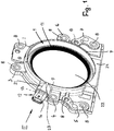
- the sealing flange has an annular support 1, which consists of hard plastic.
- Suitable plastics for the carrier 1 are, for example, high-performance thermoplastics such as PPS, suitable polyamides or PPA, but also thermosets, such as phenolic resins.
- the high-performance thermoplastics and the thermosets are each compounds containing additives depending on the application, such as glass or carbon fibers, mineral fillers and the like.
- transverse attachment points 2 to 7 which are each provided with at least one passage opening 8 for screws with which the sealing flange can be screwed to the crankcase.
- the arrangement and design of the attachment points 2 to 7 depends on the design of the respective crankcase. The in the FIGS. 1 and 2 illustrated training and arrangement of the mounting tabs 2 to 7 is therefore not to be regarded as limiting, but represents only one possible embodiment.
- At its side facing the crankcase (not shown) side surface of the sealing flange or the carrier 1 is provided with at least one static seal, which may be formed as a sealing ring and extend over the circumference of the carrier 1.
- the static seal is secured in a groove on the front side of the carrier 1 in a known manner. Since such static seals are known on sealing flanges for crankshafts, their design and arrangement will not be described in detail.
- the carrier 1 has a passage opening 22 in which a dynamic seal 11 is arranged in a known manner. It extends over the circumference of the passage opening 22 and is sealingly against the crankshaft which extends through the carrier 1.
- the dynamic seal 11 may be an elastomeric seal.
- the dynamic seal 11 is made of polyfluorocarbon, in particular polytetrafluoroethylene.
- the dynamic seal 11 is made of friction-minimized materials, so that the wear and the friction losses of the dynamic seal 11 is minimal and in this way a long life is ensured.
- the passage opening 22 has at the transition to the in the Fig. 1 and 2 shown side surface of the sealing flange on a radially outwardly conically opening wall portion 10, to which a circumferential, flat and lying in the side surface annular surface 9 connects. It advantageously has the same radial width over most of its circumference and is widened in the sensor region 23 and in the foot region 24 of the sealing flange.
- the annular surface 9 may also have a different design depending on the shape and / or design of the sealing flange.
- the illustrated and described shape of the annular surface 9 is therefore not to be understood as limiting.
- the sealing flange is provided with a speed and position sensor 12 (hereinafter referred to as sensor), which is used for the engine control and with one rotatably seated on the crankshaft encoder wheel cooperates in a known manner.
- the sensor 12 consists essentially of an electronic assembly 13 which is integrated in the sealing flange.
- the electronic assembly 13 is first inserted into the injection mold and then encapsulated in the injection molding with the plastic.
- Corresponding positioning aids for the electronic assembly 13 are arranged in the injection molding tool, so that it is arranged with exact position in the injection-molded sealing flange.
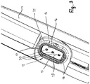
- the sensor 12 has a transversely projecting from the carrier 1 female part 14 into which a plug of a corresponding sensor line can be inserted.
- This bushing part 14 is also produced during injection molding of the sealing flange, so that it does not have to be mounted separately on the carrier 1 of the sealing flange.
- the socket part 14 has parallel straight straight wall sections 15, 16 (FIG. Fig. 3 ), which merge at their ends via curved wall sections 17, 18 into each other.
- the receiving part 14 has a bottom 19, from which contacts 20 protrude, which are conductively connected to the electronic module 13 and which cooperate with corresponding mating contacts of the socket to be plugged into the connector 14 of the sensor line.
- the sensor 12 is arranged on the annular support 1 so that it is located in the area adjacent to the dynamic seal 11. This allows the sensor 12 to cooperate reliably with the sender wheel of the crankshaft.
- the shape of the female part 14 depends on the installation conditions in the vehicle.
- the female part 14 extends straight.
- it can also be curved, z-shaped over its length or shaped in some other way, depending on the existing installation conditions in the vehicle.
- the socket part 14 is based on a base body 21, which in the illustrated embodiment has a larger cross-section than the socket part 14.
- the main body 21 extends approximately over the entire axial width of the carrier 1.
- the electronic assembly 13 is located in the region of this base body 21, the also protrudes transversely from the annular support 1 and is integrally formed with it. Due to the large cross-sectional width of the base body 21, the electronic assembly 13 is reliably protected. Since the electronic assembly 13 is poured in the injection molding in the carrier 1 of the sealing flange, there is an excellent radial, tangential and axial positioning of the assembly 13. Since it is embedded in the material of the sealing flange, it is insensitive to vibrations and shocks. This contributes to the high measurement accuracy of the sensor 12.
- the female part 14 and the main body 21 may also have the same or substantially the same cross section. Even in such a case, the assembly 13 is reliably protected.
- the sensor 12 does not have to be subsequently mounted on the sealing flange or its carrier 1 as a separate structural unit, no guides are required for the sensor, which would lead to interruptions in the wall section 10 and in the annular surface 9. Due to the closed surfaces 9, 10 no deposits in cavities and the like. Formed, as they occur in conventional sealing flanges, in which the sensor 12 is screwed to the carrier 1. Conversely, it is ensured by the closed surfaces 9, 10 that no dirt particles are drawn from the outside into the inner region of the sealing flange.
- the overpressure bell checks the tightness of the sealing flange. It is attached to an end face of the sealing flange so that it seals over its circumference both on the annular surface 9 and on the wall section 10 the carrier 1 can rest. If an overpressure is now applied via the overpressure bell, then the overpressure must be maintained for a predetermined time. If this is the case, then this is an indication of the tightness of the sealing flange. However, if the overpressure falls within the specified measuring time, this indicates that the sealing flange has leaks. Since the surfaces 9, 10 are closed, the leak test can be made simple and reliable.
- the sealing flange is characterized by a low weight, because the additional, previously required for attaching the sensor fasteners that are made of metal, have been eliminated.
- the sealing flange with integrated injection-molded sensor 12 can be manufactured in any suitable size.
- the positioning of the sensor 12 on the sealing flange can be arbitrary, so that a wide variety of sealing flanges can be used for a variety of engine designs.
- the assembly 13 only needs to be positioned in place within the injection molding tool. During the subsequent injection molding process, the sensor 12 is then in the correct position of the sealing flange.
- the sensor 12 is designed so that the sensor signals are sent via lines to the engine control.
- the signal transmission can also be wireless, for example via radio.
Landscapes
- Engineering & Computer Science (AREA)
- General Engineering & Computer Science (AREA)
- Mechanical Engineering (AREA)
- Physics & Mathematics (AREA)
- General Physics & Mathematics (AREA)
- Chemical & Material Sciences (AREA)
- Combustion & Propulsion (AREA)
- Electromagnetism (AREA)
- Measurement Of Length, Angles, Or The Like Using Electric Or Magnetic Means (AREA)
- Transmission And Conversion Of Sensor Element Output (AREA)
Applications Claiming Priority (1)
| Application Number | Priority Date | Filing Date | Title |
|---|---|---|---|
| DE202015007951.2U DE202015007951U1 (de) | 2015-11-16 | 2015-11-16 | Kurbelwellen-Dichtflansch |
Publications (2)
| Publication Number | Publication Date |
|---|---|
| EP3208454A1 true EP3208454A1 (fr) | 2017-08-23 |
| EP3208454B1 EP3208454B1 (fr) | 2020-06-03 |
Family
ID=54867323
Family Applications (1)
| Application Number | Title | Priority Date | Filing Date |
|---|---|---|---|
| EP16002339.6A Active EP3208454B1 (fr) | 2015-11-16 | 2016-11-03 | Bride étanche de vilebrequins |
Country Status (4)
| Country | Link |
|---|---|
| US (1) | US10024433B2 (fr) |
| EP (1) | EP3208454B1 (fr) |
| CN (1) | CN106704383B (fr) |
| DE (1) | DE202015007951U1 (fr) |
Cited By (1)
| Publication number | Priority date | Publication date | Assignee | Title |
|---|---|---|---|---|
| FR3154153A1 (fr) | 2023-10-13 | 2025-04-18 | Psa Automobiles Sa | Plaque metallique configuree pour assurer l’etancheite d’un moteur comprenant un joint dynamique pourvu d’au moins un segment d’arrêt aimante |
Families Citing this family (2)
| Publication number | Priority date | Publication date | Assignee | Title |
|---|---|---|---|---|
| WO2022127974A1 (fr) * | 2020-12-15 | 2022-06-23 | Schaeffler Technologies AG & Co. KG | Palier de capteur ayant un boîtier thermodurci pour détecter l'angle d'un arbre et procédé permettant de fabriquer le palier de capteur |
| CN115263596A (zh) * | 2022-07-25 | 2022-11-01 | 东风汽车集团股份有限公司 | 发动机 |
Citations (4)
| Publication number | Priority date | Publication date | Assignee | Title |
|---|---|---|---|---|
| EP1063455A2 (fr) * | 1999-06-23 | 2000-12-27 | CR Elastomere GmbH | Bride pour l'étanchéité d'une pièce tournante de machine |
| FR2828931A1 (fr) * | 2001-08-21 | 2003-02-28 | Skf Ab | Unite de montage pour systemes transmetteurs de position angulaire, par exemple de position angulaire d'un vilebrequin de vehicule automobile |
| EP1780549A2 (fr) * | 2005-11-01 | 2007-05-02 | Jtekt Corporation | Dispositif d'étanchéité avec capteur et dispositif de roulement l'utilisant |
| CN203703137U (zh) * | 2014-03-10 | 2014-07-09 | 董波 | 具有传感功能的总成油封 |
Family Cites Families (13)
| Publication number | Priority date | Publication date | Assignee | Title |
|---|---|---|---|---|
| SE452639B (sv) * | 1984-12-20 | 1987-12-07 | Saab Scania Ab | Arrangemang vid en forbrenningsmotor for anslutning av en legesavkennande givare |
| US5152538A (en) * | 1988-03-21 | 1992-10-06 | Chicago Rawhide Manufacturing Company, Inc. | Composite seal assembly |
| DE19605550C2 (de) * | 1996-02-15 | 1999-07-08 | Freudenberg Carl Fa | Radialwellendichtring |
| BR9604203A (pt) * | 1996-10-16 | 1998-05-26 | Sabo Ind & Comercio Ltda | Aperfeiçoamento em vedação |
| DE19839297C2 (de) * | 1998-08-28 | 2001-06-21 | Freudenberg Carl Fa | Dichtungsanordnung |
| NO322272B1 (no) * | 1999-03-26 | 2006-09-04 | Kongsberg Maritime As | Sensor og system for overvaking av temperatur inne i vanskelig tilgjengelige, bevegelige deler |
| JP4141588B2 (ja) * | 1999-06-02 | 2008-08-27 | 株式会社ジェイテクト | 車輪速検出装置 |
| DE19951340C2 (de) * | 1999-10-25 | 2002-07-18 | Freudenberg Carl Kg | Dichtungsanordnung |
| US7334555B2 (en) * | 2004-02-02 | 2008-02-26 | Freudenberg-Nok General Partnership | Stamped crankshaft seal retainer plate and molded encoder sensor support feature |
| US7341257B2 (en) * | 2004-04-15 | 2008-03-11 | Federal-Mogul World Wide, Inc | Integrated sensor-seal module for detecting angular position of a crankshaft |
| JP2006009979A (ja) * | 2004-06-28 | 2006-01-12 | Nok Corp | センサ付き密封装置 |
| DE102010028232A1 (de) * | 2010-04-27 | 2011-10-27 | Robert Bosch Gmbh | Sensorbaugruppe für ein Fahrzeug und Vorrichtung zur Erfassung von Drehbewegungen eines Radlagers |
| DE102014200273B4 (de) * | 2014-01-10 | 2018-04-19 | Ford Global Technologies, Llc | Lagerkappe |
-
2015
- 2015-11-16 DE DE202015007951.2U patent/DE202015007951U1/de not_active Expired - Lifetime
-
2016
- 2016-11-03 EP EP16002339.6A patent/EP3208454B1/fr active Active
- 2016-11-15 US US15/351,631 patent/US10024433B2/en active Active
- 2016-11-16 CN CN201611034189.1A patent/CN106704383B/zh active Active
Patent Citations (4)
| Publication number | Priority date | Publication date | Assignee | Title |
|---|---|---|---|---|
| EP1063455A2 (fr) * | 1999-06-23 | 2000-12-27 | CR Elastomere GmbH | Bride pour l'étanchéité d'une pièce tournante de machine |
| FR2828931A1 (fr) * | 2001-08-21 | 2003-02-28 | Skf Ab | Unite de montage pour systemes transmetteurs de position angulaire, par exemple de position angulaire d'un vilebrequin de vehicule automobile |
| EP1780549A2 (fr) * | 2005-11-01 | 2007-05-02 | Jtekt Corporation | Dispositif d'étanchéité avec capteur et dispositif de roulement l'utilisant |
| CN203703137U (zh) * | 2014-03-10 | 2014-07-09 | 董波 | 具有传感功能的总成油封 |
Cited By (1)
| Publication number | Priority date | Publication date | Assignee | Title |
|---|---|---|---|---|
| FR3154153A1 (fr) | 2023-10-13 | 2025-04-18 | Psa Automobiles Sa | Plaque metallique configuree pour assurer l’etancheite d’un moteur comprenant un joint dynamique pourvu d’au moins un segment d’arrêt aimante |
Also Published As
| Publication number | Publication date |
|---|---|
| DE202015007951U1 (de) | 2015-12-07 |
| US10024433B2 (en) | 2018-07-17 |
| EP3208454B1 (fr) | 2020-06-03 |
| CN106704383A (zh) | 2017-05-24 |
| US20170138481A1 (en) | 2017-05-18 |
| CN106704383B (zh) | 2020-03-31 |
Similar Documents
| Publication | Publication Date | Title |
|---|---|---|
| EP3175150B1 (fr) | Dispositif d'actionnement hydraulique ou pneumatique pour actionner des actionneurs dans une boîte de vitesse de véhicule automobile | |
| DE102008047466A1 (de) | Magnetbaugruppe für eine Drehmoment- und/oder Drehwinkelsensoranordnung mit einem Magnetring und Herstellungsverfahren | |
| DE112015000086B4 (de) | Raddrehzahlsensor und Herstellungsverfahren dafür | |
| DE102014208422A1 (de) | Radlagereinheit | |
| DE102009039082A1 (de) | Magnetbaugruppe für eine Drehmoment- und/oder Drehwinkelsensoranordnung mit einem Magnetring und Herstellungsverfahren | |
| EP3208454B1 (fr) | Bride étanche de vilebrequins | |
| DE102012210412B4 (de) | Sensorvorrichtung mit o-ring | |
| DE102016104882A1 (de) | Wellendichtungssystem | |
| DE102011118775B3 (de) | Vorrichtung zur berührungslosen Erfassung der Relativposition zweier relativ zueinander bewegbarer Teile | |
| DE102010013214A1 (de) | Radlageranordnung mit Sensoranschlag | |
| DE102016213359A1 (de) | Lageranordnung | |
| DE102017108717A1 (de) | Scheibenbremse für ein Nutzfahrzeug | |
| DE102010028232A1 (de) | Sensorbaugruppe für ein Fahrzeug und Vorrichtung zur Erfassung von Drehbewegungen eines Radlagers | |
| WO2016124179A1 (fr) | Unite de palier de roue | |
| DE102009016298A1 (de) | Wegmesssystem für Kupplungsausrücksysteme | |
| DE60306869T2 (de) | Dynamische Dichtung mit Winkelkodierung für rotierende Wellen, Vorrichtung mit einer solchen Dichtungund und Herstellungsverfahren | |
| EP1503096A2 (fr) | Organe de retenue pour la fixation d'au moins un palier | |
| DE102016121643A1 (de) | Messanordnung zur Bestimmung und/oder Überwachung zumindest einer Prozessgröße eines Mediums in einer Rohrleitung | |
| DE102009016284A1 (de) | Befestigungsanordnung | |
| WO2016091370A1 (fr) | Enrouleur de ceinture avec un anneau codeur de signal | |
| DE102014202354A1 (de) | Dichtvorrichtung für ein Sensorgehäuse | |
| DE102009057491A1 (de) | Drosselklappenvorrichtung | |
| DE102015104892A1 (de) | Vorrichtung zum Erfassen eines Bremsbelagverschleißes sowie Anordnung aus einem Führungsholm und einem sensierbaren Element | |
| DE102021116435A1 (de) | Sensoranordnung mit bündigen oder versenktem Aufbau, insbesondere für ein Wälzlager | |
| DE102021213854A1 (de) | Dämpfervorrichtung mit aus Kunststoff gefertigter Schutzkappe und Schutzrohr sowie Verfahren zum Herstellen der Dämpfervorrichtung |
Legal Events
| Date | Code | Title | Description |
|---|---|---|---|
| STAA | Information on the status of an ep patent application or granted ep patent |
Free format text: STATUS: UNKNOWN |
|
| PUAI | Public reference made under article 153(3) epc to a published international application that has entered the european phase |
Free format text: ORIGINAL CODE: 0009012 |
|
| STAA | Information on the status of an ep patent application or granted ep patent |
Free format text: STATUS: THE APPLICATION HAS BEEN PUBLISHED |
|
| AK | Designated contracting states |
Kind code of ref document: A1 Designated state(s): AL AT BE BG CH CY CZ DE DK EE ES FI FR GB GR HR HU IE IS IT LI LT LU LV MC MK MT NL NO PL PT RO RS SE SI SK SM TR |
|
| AX | Request for extension of the european patent |
Extension state: BA ME |
|
| STAA | Information on the status of an ep patent application or granted ep patent |
Free format text: STATUS: REQUEST FOR EXAMINATION WAS MADE |
|
| 17P | Request for examination filed |
Effective date: 20180223 |
|
| RBV | Designated contracting states (corrected) |
Designated state(s): AL AT BE BG CH CY CZ DE DK EE ES FI FR GB GR HR HU IE IS IT LI LT LU LV MC MK MT NL NO PL PT RO RS SE SI SK SM TR |
|
| RIC1 | Information provided on ipc code assigned before grant |
Ipc: F02F 7/00 20060101AFI20190709BHEP Ipc: F16J 15/326 20160101ALI20190709BHEP |
|
| GRAP | Despatch of communication of intention to grant a patent |
Free format text: ORIGINAL CODE: EPIDOSNIGR1 |
|
| STAA | Information on the status of an ep patent application or granted ep patent |
Free format text: STATUS: GRANT OF PATENT IS INTENDED |
|
| INTG | Intention to grant announced |
Effective date: 20191018 |
|
| RAP1 | Party data changed (applicant data changed or rights of an application transferred) |
Owner name: KACO GMBH + CO. KG |
|
| GRAJ | Information related to disapproval of communication of intention to grant by the applicant or resumption of examination proceedings by the epo deleted |
Free format text: ORIGINAL CODE: EPIDOSDIGR1 |
|
| STAA | Information on the status of an ep patent application or granted ep patent |
Free format text: STATUS: REQUEST FOR EXAMINATION WAS MADE |
|
| GRAJ | Information related to disapproval of communication of intention to grant by the applicant or resumption of examination proceedings by the epo deleted |
Free format text: ORIGINAL CODE: EPIDOSDIGR1 |
|
| STAA | Information on the status of an ep patent application or granted ep patent |
Free format text: STATUS: GRANT OF PATENT IS INTENDED |
|
| GRAP | Despatch of communication of intention to grant a patent |
Free format text: ORIGINAL CODE: EPIDOSNIGR1 |
|
| INTC | Intention to grant announced (deleted) | ||
| INTG | Intention to grant announced |
Effective date: 20200312 |
|
| GRAS | Grant fee paid |
Free format text: ORIGINAL CODE: EPIDOSNIGR3 |
|
| GRAA | (expected) grant |
Free format text: ORIGINAL CODE: 0009210 |
|
| STAA | Information on the status of an ep patent application or granted ep patent |
Free format text: STATUS: THE PATENT HAS BEEN GRANTED |
|
| AK | Designated contracting states |
Kind code of ref document: B1 Designated state(s): AL AT BE BG CH CY CZ DE DK EE ES FI FR GB GR HR HU IE IS IT LI LT LU LV MC MK MT NL NO PL PT RO RS SE SI SK SM TR |
|
| REG | Reference to a national code |
Ref country code: GB Ref legal event code: FG4D Free format text: NOT ENGLISH |
|
| REG | Reference to a national code |
Ref country code: CH Ref legal event code: EP Ref country code: AT Ref legal event code: REF Ref document number: 1277252 Country of ref document: AT Kind code of ref document: T Effective date: 20200615 |
|
| REG | Reference to a national code |
Ref country code: DE Ref legal event code: R096 Ref document number: 502016010094 Country of ref document: DE |
|
| REG | Reference to a national code |
Ref country code: LT Ref legal event code: MG4D |
|
| PG25 | Lapsed in a contracting state [announced via postgrant information from national office to epo] |
Ref country code: SE Free format text: LAPSE BECAUSE OF FAILURE TO SUBMIT A TRANSLATION OF THE DESCRIPTION OR TO PAY THE FEE WITHIN THE PRESCRIBED TIME-LIMIT Effective date: 20200603 Ref country code: LT Free format text: LAPSE BECAUSE OF FAILURE TO SUBMIT A TRANSLATION OF THE DESCRIPTION OR TO PAY THE FEE WITHIN THE PRESCRIBED TIME-LIMIT Effective date: 20200603 Ref country code: GR Free format text: LAPSE BECAUSE OF FAILURE TO SUBMIT A TRANSLATION OF THE DESCRIPTION OR TO PAY THE FEE WITHIN THE PRESCRIBED TIME-LIMIT Effective date: 20200904 Ref country code: FI Free format text: LAPSE BECAUSE OF FAILURE TO SUBMIT A TRANSLATION OF THE DESCRIPTION OR TO PAY THE FEE WITHIN THE PRESCRIBED TIME-LIMIT Effective date: 20200603 Ref country code: NO Free format text: LAPSE BECAUSE OF FAILURE TO SUBMIT A TRANSLATION OF THE DESCRIPTION OR TO PAY THE FEE WITHIN THE PRESCRIBED TIME-LIMIT Effective date: 20200903 |
|
| REG | Reference to a national code |
Ref country code: NL Ref legal event code: MP Effective date: 20200603 |
|
| PG25 | Lapsed in a contracting state [announced via postgrant information from national office to epo] |
Ref country code: LV Free format text: LAPSE BECAUSE OF FAILURE TO SUBMIT A TRANSLATION OF THE DESCRIPTION OR TO PAY THE FEE WITHIN THE PRESCRIBED TIME-LIMIT Effective date: 20200603 Ref country code: HR Free format text: LAPSE BECAUSE OF FAILURE TO SUBMIT A TRANSLATION OF THE DESCRIPTION OR TO PAY THE FEE WITHIN THE PRESCRIBED TIME-LIMIT Effective date: 20200603 Ref country code: RS Free format text: LAPSE BECAUSE OF FAILURE TO SUBMIT A TRANSLATION OF THE DESCRIPTION OR TO PAY THE FEE WITHIN THE PRESCRIBED TIME-LIMIT Effective date: 20200603 Ref country code: BG Free format text: LAPSE BECAUSE OF FAILURE TO SUBMIT A TRANSLATION OF THE DESCRIPTION OR TO PAY THE FEE WITHIN THE PRESCRIBED TIME-LIMIT Effective date: 20200903 |
|
| PG25 | Lapsed in a contracting state [announced via postgrant information from national office to epo] |
Ref country code: NL Free format text: LAPSE BECAUSE OF FAILURE TO SUBMIT A TRANSLATION OF THE DESCRIPTION OR TO PAY THE FEE WITHIN THE PRESCRIBED TIME-LIMIT Effective date: 20200603 Ref country code: AL Free format text: LAPSE BECAUSE OF FAILURE TO SUBMIT A TRANSLATION OF THE DESCRIPTION OR TO PAY THE FEE WITHIN THE PRESCRIBED TIME-LIMIT Effective date: 20200603 |
|
| PG25 | Lapsed in a contracting state [announced via postgrant information from national office to epo] |
Ref country code: PT Free format text: LAPSE BECAUSE OF FAILURE TO SUBMIT A TRANSLATION OF THE DESCRIPTION OR TO PAY THE FEE WITHIN THE PRESCRIBED TIME-LIMIT Effective date: 20201006 Ref country code: RO Free format text: LAPSE BECAUSE OF FAILURE TO SUBMIT A TRANSLATION OF THE DESCRIPTION OR TO PAY THE FEE WITHIN THE PRESCRIBED TIME-LIMIT Effective date: 20200603 Ref country code: CZ Free format text: LAPSE BECAUSE OF FAILURE TO SUBMIT A TRANSLATION OF THE DESCRIPTION OR TO PAY THE FEE WITHIN THE PRESCRIBED TIME-LIMIT Effective date: 20200603 Ref country code: ES Free format text: LAPSE BECAUSE OF FAILURE TO SUBMIT A TRANSLATION OF THE DESCRIPTION OR TO PAY THE FEE WITHIN THE PRESCRIBED TIME-LIMIT Effective date: 20200603 Ref country code: EE Free format text: LAPSE BECAUSE OF FAILURE TO SUBMIT A TRANSLATION OF THE DESCRIPTION OR TO PAY THE FEE WITHIN THE PRESCRIBED TIME-LIMIT Effective date: 20200603 Ref country code: IT Free format text: LAPSE BECAUSE OF FAILURE TO SUBMIT A TRANSLATION OF THE DESCRIPTION OR TO PAY THE FEE WITHIN THE PRESCRIBED TIME-LIMIT Effective date: 20200603 Ref country code: SM Free format text: LAPSE BECAUSE OF FAILURE TO SUBMIT A TRANSLATION OF THE DESCRIPTION OR TO PAY THE FEE WITHIN THE PRESCRIBED TIME-LIMIT Effective date: 20200603 |
|
| PG25 | Lapsed in a contracting state [announced via postgrant information from national office to epo] |
Ref country code: PL Free format text: LAPSE BECAUSE OF FAILURE TO SUBMIT A TRANSLATION OF THE DESCRIPTION OR TO PAY THE FEE WITHIN THE PRESCRIBED TIME-LIMIT Effective date: 20200603 Ref country code: SK Free format text: LAPSE BECAUSE OF FAILURE TO SUBMIT A TRANSLATION OF THE DESCRIPTION OR TO PAY THE FEE WITHIN THE PRESCRIBED TIME-LIMIT Effective date: 20200603 Ref country code: IS Free format text: LAPSE BECAUSE OF FAILURE TO SUBMIT A TRANSLATION OF THE DESCRIPTION OR TO PAY THE FEE WITHIN THE PRESCRIBED TIME-LIMIT Effective date: 20201003 |
|
| REG | Reference to a national code |
Ref country code: DE Ref legal event code: R097 Ref document number: 502016010094 Country of ref document: DE |
|
| PLBE | No opposition filed within time limit |
Free format text: ORIGINAL CODE: 0009261 |
|
| STAA | Information on the status of an ep patent application or granted ep patent |
Free format text: STATUS: NO OPPOSITION FILED WITHIN TIME LIMIT |
|
| PG25 | Lapsed in a contracting state [announced via postgrant information from national office to epo] |
Ref country code: DK Free format text: LAPSE BECAUSE OF FAILURE TO SUBMIT A TRANSLATION OF THE DESCRIPTION OR TO PAY THE FEE WITHIN THE PRESCRIBED TIME-LIMIT Effective date: 20200603 |
|
| 26N | No opposition filed |
Effective date: 20210304 |
|
| PG25 | Lapsed in a contracting state [announced via postgrant information from national office to epo] |
Ref country code: SI Free format text: LAPSE BECAUSE OF FAILURE TO SUBMIT A TRANSLATION OF THE DESCRIPTION OR TO PAY THE FEE WITHIN THE PRESCRIBED TIME-LIMIT Effective date: 20200603 |
|
| PG25 | Lapsed in a contracting state [announced via postgrant information from national office to epo] |
Ref country code: MC Free format text: LAPSE BECAUSE OF FAILURE TO SUBMIT A TRANSLATION OF THE DESCRIPTION OR TO PAY THE FEE WITHIN THE PRESCRIBED TIME-LIMIT Effective date: 20200603 |
|
| REG | Reference to a national code |
Ref country code: CH Ref legal event code: PL |
|
| GBPC | Gb: european patent ceased through non-payment of renewal fee |
Effective date: 20201103 |
|
| PG25 | Lapsed in a contracting state [announced via postgrant information from national office to epo] |
Ref country code: LU Free format text: LAPSE BECAUSE OF NON-PAYMENT OF DUE FEES Effective date: 20201103 |
|
| REG | Reference to a national code |
Ref country code: BE Ref legal event code: MM Effective date: 20201130 |
|
| PG25 | Lapsed in a contracting state [announced via postgrant information from national office to epo] |
Ref country code: LI Free format text: LAPSE BECAUSE OF NON-PAYMENT OF DUE FEES Effective date: 20201130 Ref country code: CH Free format text: LAPSE BECAUSE OF NON-PAYMENT OF DUE FEES Effective date: 20201130 |
|
| PG25 | Lapsed in a contracting state [announced via postgrant information from national office to epo] |
Ref country code: FR Free format text: LAPSE BECAUSE OF NON-PAYMENT OF DUE FEES Effective date: 20201130 Ref country code: IE Free format text: LAPSE BECAUSE OF NON-PAYMENT OF DUE FEES Effective date: 20201103 |
|
| PG25 | Lapsed in a contracting state [announced via postgrant information from national office to epo] |
Ref country code: GB Free format text: LAPSE BECAUSE OF NON-PAYMENT OF DUE FEES Effective date: 20201103 |
|
| PG25 | Lapsed in a contracting state [announced via postgrant information from national office to epo] |
Ref country code: IS Free format text: LAPSE BECAUSE OF FAILURE TO SUBMIT A TRANSLATION OF THE DESCRIPTION OR TO PAY THE FEE WITHIN THE PRESCRIBED TIME-LIMIT Effective date: 20201003 Ref country code: TR Free format text: LAPSE BECAUSE OF FAILURE TO SUBMIT A TRANSLATION OF THE DESCRIPTION OR TO PAY THE FEE WITHIN THE PRESCRIBED TIME-LIMIT Effective date: 20200603 Ref country code: MT Free format text: LAPSE BECAUSE OF FAILURE TO SUBMIT A TRANSLATION OF THE DESCRIPTION OR TO PAY THE FEE WITHIN THE PRESCRIBED TIME-LIMIT Effective date: 20200603 Ref country code: CY Free format text: LAPSE BECAUSE OF FAILURE TO SUBMIT A TRANSLATION OF THE DESCRIPTION OR TO PAY THE FEE WITHIN THE PRESCRIBED TIME-LIMIT Effective date: 20200603 |
|
| PG25 | Lapsed in a contracting state [announced via postgrant information from national office to epo] |
Ref country code: MK Free format text: LAPSE BECAUSE OF FAILURE TO SUBMIT A TRANSLATION OF THE DESCRIPTION OR TO PAY THE FEE WITHIN THE PRESCRIBED TIME-LIMIT Effective date: 20200603 |
|
| PG25 | Lapsed in a contracting state [announced via postgrant information from national office to epo] |
Ref country code: BE Free format text: LAPSE BECAUSE OF NON-PAYMENT OF DUE FEES Effective date: 20201130 |
|
| REG | Reference to a national code |
Ref country code: AT Ref legal event code: MM01 Ref document number: 1277252 Country of ref document: AT Kind code of ref document: T Effective date: 20211103 |
|
| PG25 | Lapsed in a contracting state [announced via postgrant information from national office to epo] |
Ref country code: AT Free format text: LAPSE BECAUSE OF NON-PAYMENT OF DUE FEES Effective date: 20211103 |
|
| P01 | Opt-out of the competence of the unified patent court (upc) registered |
Effective date: 20230824 |
|
| PGFP | Annual fee paid to national office [announced via postgrant information from national office to epo] |
Ref country code: DE Payment date: 20231127 Year of fee payment: 8 |
|
| REG | Reference to a national code |
Ref country code: DE Ref legal event code: R119 Ref document number: 502016010094 Country of ref document: DE |
|
| PG25 | Lapsed in a contracting state [announced via postgrant information from national office to epo] |
Ref country code: DE Free format text: LAPSE BECAUSE OF NON-PAYMENT OF DUE FEES Effective date: 20250603 |