EP2154372A1 - Zahnradpumpe - Google Patents
Zahnradpumpe Download PDFInfo
- Publication number
- EP2154372A1 EP2154372A1 EP09010090A EP09010090A EP2154372A1 EP 2154372 A1 EP2154372 A1 EP 2154372A1 EP 09010090 A EP09010090 A EP 09010090A EP 09010090 A EP09010090 A EP 09010090A EP 2154372 A1 EP2154372 A1 EP 2154372A1
- Authority
- EP
- European Patent Office
- Prior art keywords
- chamber
- pump according
- opening
- duct
- rear cover
- Prior art date
- Legal status (The legal status is an assumption and is not a legal conclusion. Google has not performed a legal analysis and makes no representation as to the accuracy of the status listed.)
- Granted
Links
Images


Classifications
-
- F—MECHANICAL ENGINEERING; LIGHTING; HEATING; WEAPONS; BLASTING
- F04—POSITIVE - DISPLACEMENT MACHINES FOR LIQUIDS; PUMPS FOR LIQUIDS OR ELASTIC FLUIDS
- F04C—ROTARY-PISTON, OR OSCILLATING-PISTON, POSITIVE-DISPLACEMENT MACHINES FOR LIQUIDS; ROTARY-PISTON, OR OSCILLATING-PISTON, POSITIVE-DISPLACEMENT PUMPS
- F04C15/00—Component parts, details or accessories of machines, pumps or pumping installations, not provided for in groups F04C2/00 - F04C14/00
- F04C15/0042—Systems for the equilibration of forces acting on the machines or pump
-
- F—MECHANICAL ENGINEERING; LIGHTING; HEATING; WEAPONS; BLASTING
- F04—POSITIVE - DISPLACEMENT MACHINES FOR LIQUIDS; PUMPS FOR LIQUIDS OR ELASTIC FLUIDS
- F04C—ROTARY-PISTON, OR OSCILLATING-PISTON, POSITIVE-DISPLACEMENT MACHINES FOR LIQUIDS; ROTARY-PISTON, OR OSCILLATING-PISTON, POSITIVE-DISPLACEMENT PUMPS
- F04C14/00—Control of, monitoring of, or safety arrangements for, machines, pumps or pumping installations
- F04C14/04—Control of, monitoring of, or safety arrangements for, machines, pumps or pumping installations specially adapted for reversible machines or pumps
-
- F—MECHANICAL ENGINEERING; LIGHTING; HEATING; WEAPONS; BLASTING
- F04—POSITIVE - DISPLACEMENT MACHINES FOR LIQUIDS; PUMPS FOR LIQUIDS OR ELASTIC FLUIDS
- F04C—ROTARY-PISTON, OR OSCILLATING-PISTON, POSITIVE-DISPLACEMENT MACHINES FOR LIQUIDS; ROTARY-PISTON, OR OSCILLATING-PISTON, POSITIVE-DISPLACEMENT PUMPS
- F04C15/00—Component parts, details or accessories of machines, pumps or pumping installations, not provided for in groups F04C2/00 - F04C14/00
- F04C15/0003—Sealing arrangements in rotary-piston machines or pumps
- F04C15/0023—Axial sealings for working fluid
- F04C15/0026—Elements specially adapted for sealing of the lateral faces of intermeshing-engagement type machines or pumps, e.g. gear machines or pumps
-
- F—MECHANICAL ENGINEERING; LIGHTING; HEATING; WEAPONS; BLASTING
- F04—POSITIVE - DISPLACEMENT MACHINES FOR LIQUIDS; PUMPS FOR LIQUIDS OR ELASTIC FLUIDS
- F04C—ROTARY-PISTON, OR OSCILLATING-PISTON, POSITIVE-DISPLACEMENT MACHINES FOR LIQUIDS; ROTARY-PISTON, OR OSCILLATING-PISTON, POSITIVE-DISPLACEMENT PUMPS
- F04C2/00—Rotary-piston machines or pumps
- F04C2/08—Rotary-piston machines or pumps of intermeshing-engagement type, i.e. with engagement of co-operating members similar to that of toothed gearing
- F04C2/12—Rotary-piston machines or pumps of intermeshing-engagement type, i.e. with engagement of co-operating members similar to that of toothed gearing of other than internal-axis type
- F04C2/14—Rotary-piston machines or pumps of intermeshing-engagement type, i.e. with engagement of co-operating members similar to that of toothed gearing of other than internal-axis type with toothed rotary pistons
- F04C2/18—Rotary-piston machines or pumps of intermeshing-engagement type, i.e. with engagement of co-operating members similar to that of toothed gearing of other than internal-axis type with toothed rotary pistons with similar tooth forms
Definitions
- the present invention refers to a positive displacement rotary gear pump.
- the present invention refers to a positive displacement pump of the reversible type, i.e. one that is able to operate in both rotational directions, with inversion of suction and delivery, without loss of yield.
- Positive displacement rotary gear pumps are used in various industrial sectors, where they transfer mechanical energy to a fluid operator that is intended to engage mechanical actuators such as linear hydraulic jacks.
- Gear pumps commonly consist of a pump body, comprising an inlet and outlet for suction and delivery, which house two toothed wheels that mesh with each other, supported by apposite bushes.
- a pump body comprising an inlet and outlet for suction and delivery, which house two toothed wheels that mesh with each other, supported by apposite bushes.
- the drive wheel or pinion usually one of the two wheels, called the drive wheel or pinion and made to rotate by means of an external motor, engages in rotation the other wheel, which is called the driven wheel.
- This axial push involves a slow and inexorable wear and tear of the lateral faces of the toothed wheels and the support bushes, and consequently a loss of sealing between delivery and suction and therefore over time causing a considerable decrease in overall performance.
- the pump may be configured in such a way that an axially pushing force is created that is opposed to the one generated by the rotating toothed wheels.
- the shafts of the two wheels are made to rest on two abutment pins that are mounted in an axially slidable and sealing manner between the respective housings on the rear cover itself or on an appropriate intermediate plate.
- the ends of the backing pins opposite the shafts flank a shared chamber located on the rear cover and placed in communication with the delivery outlet of the pump. In this manner the fluid under delivery pressure that comes to occupy this chamber, exercises a direct pressure on the two pins, pressing them contrary to the axial push generated by the rotating toothed wheels.
- the bushes proximal to the rear cover are with their annular profiles in correspondence with said chamber, so that they too are exposed to the pressure exercised by the fluid under delivery pressure.
- the chamber in communication with the delivery outlet, is commonly made with an omega conformation obtained in correspondence with the internal part of the external edge of the bushes, whose external profile is substantially shaped like a figure "eight".
- This omega-shaped configuration of the chambers placed in communication with the delivery outlet allows one to have a surface extension that is adequate and greater than that of the common further chamber, usually a small channel placed in communication with the suction inlet and therefore reached by the suction fluid that is definitely pressurized less than that of the delivery.
- the omega-shaped chamber having a larger extension will be filled with pressurized suction fluid, whereas the small channel will be filled with pressurized delivery fluid (higher than that of the suction fluid).
- gear pumps known from prior art are not very suitable to be used in a reversible manner, i.e. in such a manner that the functions of the suction inlet and delivery outlet can be inverted.
- the object of the present invention is providing a positive displacement rotary gear pump having structural and functional characteristics that meet with the abovementioned requirements and that at the same time overcome the inconveniences described above with reference to the prior art.
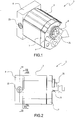
- 1 generally denotes a positive displacement rotary gear pump according to the present invention.
- the pump 1 comprises generally speaking a pump body 2 which internally houses a toothed driving wheel 3 and a toothed driven wheel 4 ( Fig.4 ).
- toothed wheels 3,4 are of the cylindrical kind with helical teeth, but naturally the invention can be applied also in cases where different wheel types are used, e.g. with cylindrical gears with straight teeth.
- the pump body 2 is provided with a first opening 5 and a second opening 6, that alternately function as suction inlet or delivery outlet, according to the direction of rotation of the toothed wheels 3, 4, i.e. functioning according to the direction of rotation transferred by a motor, not illustrated, to the driving wheel 3.
- the Figures illustrate a structure that allows for the obtainment of a principal functioning in which the first and the second opening 5 and 6 respectively function as suction inlet and delivery outlet.
- a front cover 7 and a rear cover 8 respectively are fastened with regular fastening means such as screws.
- openings for suction and delivery 5, 6 are axially obtained on the front cover 7, but of course any other collocation may be adopted, such as placed opposite each other on the pump body 2.
- the extremity 31 of the shaft 32 of the drive wheel 3 to be attached to the pump's motor drive shaft passes through and protrudes from the front cover 7.
- each pair of bushes 9, 10 is formed by two separate elements, but it is also possible that each pair of bushes is made as a single piece.
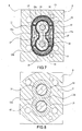
- the two rear bushes 10 rest against the rear cover 8 on which there are a first, a second and a third chamber that will be better described further on ( Fig. 7 ).
- the first chamber is in communication by means of a central appendix 11a with the interior of the pump body 2 in the area reached by the fluid that comes through the first opening 5, in correspondence to the suction inlet in the illustrated example.
- the second chamber 12 is in communication by means of a central appendix 12a, with the interior of the pump body 2 in the area reached by the fluid that comes through the second opening 6, in correspondence to the delivery outlet in the illustrated example.
- the first chamber 11 communicates with the first opening 5 and the second chamber communicates with the second opening 6.
- the third chamber is concretized in two distinct opposite areas 13a and 13b and interconnected by a connection duct 14 closed at the ends and located in the rear cover 8. This connection is created by two parallel lines 15 that run from the connection duct 14 and that lead centrally into the two areas 13a and 13b ( Fig. 4 ).
- connection duct 14 is placed selectively in fluid communication with the first chamber 11 or the second chamber 12 by means of a first transverse duct 16 that is closed at the ends by two caps 22 that are accessible from the outside, and from which two parallel lines 17 run that lead into the first and second chamber 11, 12 at a respective central hole in the appendices 11a, 12a ( Fig. 5 ).
- both the connection duct 14 and the first duct 16 are located inside the rear cover 8 where they cross centrally, forming a crossed configuration.
- interception means In order to fluidly connect in a selective manner the connection duct 14 with the first chamber 11 or the second chamber 12 so that the two areas 13a, 13b are connected exclusively with either the first chamber 11 or the second chamber 12, the use of interception means is provided which in the example take the form of a shutter body 18 inside the first duct 16.
- said shutter body 18 has a cylindrical configuration with a variable cross-section and mounted in an axially floating manner inside the first duct 16.
- the shutter body 18 is made of a single piece of three cylindrical elements, of which the central one 18a has a larger cross-section, and the two lateral elements 18b, identical in the example, are also cylindrical but with smaller cross-sections.
- the dimensions of the cylindrical elements 18a, 18b are chosen specifically to allow for the possibility of interruption of the communication between the central element 18a with the larger cross-section and one of the two chambers 11 or 12.
- the diameter of the central element 18a is close to the internal diameter of the duct 16 within which it slides.
- the interruption of the connection occurs when the central element 18a with the larger diameter is moved, always on the inside of the first duct 16, along one of the lines 17 (to obstruct it) that lead to the first chamber 11 and the second chamber 12, leaving open the remaining line 17 and as a result creating a unique connection with either the first chambers 11 or the second chamber 12.
- the movement of the shutter body 18 inside the duct 16 is controlled by the difference in pressure between the delivery and the suction, which in practice corresponds to a pressure difference between the first chamber 11 and the second chamber 12.
- the shutter body 18 allows the two areas 13a, 13b of the third chamber to be placed in unique communication with only one of either the first chamber 11 or the second chamber 12, the one with the fluid that is pressurized the most, i.e. that chamber that is in communication with the opening that serves as delivery outlet. This is due to the fact that the shutter body 18, pushed by the pressure of the delivery fluid that reaches the first duct 16 through one of the two lines 17, interrupts the communication with the chamber with the fluid with the suction pressure, with is lower than that of delivery.
- the shutter body 18 functions as an isolator between the chamber (denoted by 11 in the example) placed under suction pressure and the first duct 16.
- the chambers 11, 12, 13a, 13b obtained on the rear cover 8 are arranged in correspondence to the rear faces of the rear bushes 10 that rest directly on the rear cover itself.
- annular profile of the rear faces of the rear bushes 10 will be positioned in correspondence with the three chambers 11, 12, 13a, 13b that are arranged along a tract that substantially replicates the profile of the bushes themselves, but nevertheless remaining within the external perimeter of these, denoted by a dashed line in figure 7 .
- first chamber 11 and the second chamber 12 are identical and arranged opposite each other, just as the two areas 13a, 13b are identical and arranged opposite each other. This should not be interpreted, however, as limiting the rights of the applicant, inasmuch as the relative arrangement of the abovementioned chambers could be different for constructive reasons.
- the three chambers 11, 12, 13a, 13b are confined by the grooves on the rear cover 8 and separated by a seal 19, opportunely located inside a shaped groove, to prevent the fluid under high pressure from seeping through to the chamber (either the first or the second) with the lower pressure.
- first chamber 11 and the second chamber 12 are completely covered by the rear bushes 10, they are nevertheless placed in communication with respectively the delivery outlet and the suction inlet, or vice versa.
- this is obtained by shaping the chambers 11 and 12 in such a way that they have respective central appendices 11a, 12a, that are not covered by the rear bushes 10 but project from the external perimeter defined by these so that they are placed directly in communication with respectively the first opening 5 and the second opening 6, as shown in Figures 7 and 8 .
- the fluid usually oil
- the pump 1 when the pump 1 is activated with the first opening 5 used for suction and the second opening 6 used for delivery, the fluid, usually oil, is aspirated through the first opening 5 and delivered through the second opening 6.
- the second chamber 12, which communicates with the second opening 6 through the appendix 12a, is reached by the high pressurized oil
- the first chamber 11 which communicates with the first opening 5 through the appendix 11a
- the high pressurized oil in the second chamber 12 pushes the shutter body 18 that is present in the first duct 16 so that it interrupts the connection between the first chamber 11 (with low pressure) and the duct 16 itself.
- the second opening 6 By reversing the operational direction the second opening 6 will be placed in suction whereas the first opening will be placed in delivery.
- the cylindrical body 18 is pushed by the force of the oil from the other side of the one of the previous operational configuration, to shut off the connection between the duct 16 and the second chamber 12, placing in communication the two areas 13a and 13b with the first chamber 11 which contains oil under delivery pressure (position not illustrated).
- the shutter body 18 isolates the duct 16 from the chamber that is in direct communication with the fluid at suction pressure, and places it in exclusive communication with the chamber that is in direct communication with the fluid at delivery pressure.
- the second duct 14, which is centrally in communication with the duct 16, is traversed all along its extension by the fluid under delivery pressure that arrives from the portion of the duct 16 that is left open by the shutter body 18. From the duct 14 the fluid reaches, by means of lines 15, the two areas 13a and 13b, in order to fill these with high pressure fluid.
- the two areas 13a and 13b are always placed in communication with the chamber that is in direct contact with the fluid that is under delivery pressure, and as a result always communicate with the opening that functions as the delivery outlet.
- the overall area occupied by the fluid under delivery pressure that acts in contrast to the axial push generated by the rotation of the toothed wheels comprises one of the two first 11 and second 12 chambers (dependent on the rotational direction), as well as the two areas 13a and 13b of the third chamber, thus creating always the same overall surface (when the first and the second chamber are identical, as they are in the example), independent from the pump's direction of rotation.
- the shafts 32, 42 rest on a pair of respective abutment means 20 that are mounted in an axially slidable and sealing manner between the respective housings 21 on the rear cover 8.
- the bases of these housings 21 are placed in communication with the connection duct 14 in order to be reached by the fluid under delivery pressure, so that the means 20 are pushed to counter the push generated by the rotation of the toothed wheels 3, 4.
- high pressure and low pressure are intended to mean delivery pressure and suction pressure respectively.
- the positive displacement rotary gear pump according to the present invention meets with the demands and overcomes the disadvantages described in the introductory part of this description with reference to the prior art.
- the positive displacement rotary gear pump according to the present invention performs with a high yield in both rotational directions of the toothed wheels.
- this pump does not need to be supplemented by any device in order to function correctly in both rotational directions, which makes inversion of rotation by the user extremely easy.
Landscapes
- Engineering & Computer Science (AREA)
- Mechanical Engineering (AREA)
- General Engineering & Computer Science (AREA)
- Rotary Pumps (AREA)
- Details And Applications Of Rotary Liquid Pumps (AREA)
Applications Claiming Priority (1)
| Application Number | Priority Date | Filing Date | Title |
|---|---|---|---|
| ITBO2008A000522A IT1390747B1 (it) | 2008-08-12 | 2008-08-12 | Pompa volumetrica rotativa ad ingranaggi |
Publications (2)
| Publication Number | Publication Date |
|---|---|
| EP2154372A1 true EP2154372A1 (de) | 2010-02-17 |
| EP2154372B1 EP2154372B1 (de) | 2014-04-16 |
Family
ID=40612872
Family Applications (1)
| Application Number | Title | Priority Date | Filing Date |
|---|---|---|---|
| EP20090010090 Not-in-force EP2154372B1 (de) | 2008-08-12 | 2009-08-05 | Zahnradpumpe |
Country Status (2)
| Country | Link |
|---|---|
| EP (1) | EP2154372B1 (de) |
| IT (1) | IT1390747B1 (de) |
Cited By (7)
| Publication number | Priority date | Publication date | Assignee | Title |
|---|---|---|---|---|
| JP2014043776A (ja) * | 2012-08-24 | 2014-03-13 | Sumitomo Precision Prod Co Ltd | 液圧装置の慣らし運転方法及び慣らし運転装置 |
| US8894385B2 (en) | 2011-11-17 | 2014-11-25 | Deere & Company | Bi-directional pump |
| ITAN20130102A1 (it) * | 2013-05-30 | 2014-12-01 | Marzocchi Pompe S P A | Pompa o motore idraulico ad ingranaggi a dentatura elicoidale con sistema idraulico per il bilanciamento di forze assiali. |
| EP3036437A4 (de) * | 2013-08-19 | 2017-09-20 | Purdue Research Foundation | Miniaturhochdruckpumpe und elektrisch-hydraulisches betätigungssystem |
| CN109915361A (zh) * | 2019-04-23 | 2019-06-21 | 济南华泰精工机械设备有限公司 | 一种具有双转向泄压通道的齿轮计量泵 |
| IT201800004230A1 (it) * | 2018-04-05 | 2019-10-05 | Apparato di pompaggio | |
| IT202300014397A1 (it) | 2023-07-10 | 2025-01-10 | Marzocchi Pompe S P A | Macchina idraulica reversibile ad ingranaggio a dentatura elicoidale con sistema idraulico bilaterale per il bilanciamento di forze assiali. |
Families Citing this family (1)
| Publication number | Priority date | Publication date | Assignee | Title |
|---|---|---|---|---|
| IT201800005600A1 (it) | 2018-05-22 | 2019-11-22 | Sistema e metodo per gestire dati pertinenti a un servizio alla ruota |
Citations (3)
| Publication number | Priority date | Publication date | Assignee | Title |
|---|---|---|---|---|
| US2541010A (en) * | 1945-12-22 | 1951-02-06 | Equi Flow Inc | Gear pump or motor |
| GB965470A (en) * | 1960-10-08 | 1964-07-29 | Bosch Gmbh Robert | Improvements in or relating to hydraulic pumps or motors |
| EP1132618A2 (de) * | 2000-03-08 | 2001-09-12 | Mario Antonio Morselli | Drehkolben-Verdrängungspumpe mit Schraubenrotoren |
-
2008
- 2008-08-12 IT ITBO2008A000522A patent/IT1390747B1/it active
-
2009
- 2009-08-05 EP EP20090010090 patent/EP2154372B1/de not_active Not-in-force
Patent Citations (3)
| Publication number | Priority date | Publication date | Assignee | Title |
|---|---|---|---|---|
| US2541010A (en) * | 1945-12-22 | 1951-02-06 | Equi Flow Inc | Gear pump or motor |
| GB965470A (en) * | 1960-10-08 | 1964-07-29 | Bosch Gmbh Robert | Improvements in or relating to hydraulic pumps or motors |
| EP1132618A2 (de) * | 2000-03-08 | 2001-09-12 | Mario Antonio Morselli | Drehkolben-Verdrängungspumpe mit Schraubenrotoren |
Cited By (17)
| Publication number | Priority date | Publication date | Assignee | Title |
|---|---|---|---|---|
| US8894385B2 (en) | 2011-11-17 | 2014-11-25 | Deere & Company | Bi-directional pump |
| JP2014043776A (ja) * | 2012-08-24 | 2014-03-13 | Sumitomo Precision Prod Co Ltd | 液圧装置の慣らし運転方法及び慣らし運転装置 |
| ITAN20130102A1 (it) * | 2013-05-30 | 2014-12-01 | Marzocchi Pompe S P A | Pompa o motore idraulico ad ingranaggi a dentatura elicoidale con sistema idraulico per il bilanciamento di forze assiali. |
| WO2014191253A1 (en) * | 2013-05-30 | 2014-12-04 | Marzocchi Pompe S.P.A. | Gear pump or hydraulic gear motor with helical toothing provided with hydraulic system for axial thrust balance. |
| CN104379934A (zh) * | 2013-05-30 | 2015-02-25 | 马尔佐基蓬佩股份公司 | 具有用于轴向推力平衡的液压系统、带有螺旋齿的齿轮泵或液压齿轮电动机 |
| CN104379934B (zh) * | 2013-05-30 | 2016-08-31 | 马尔佐基蓬佩股份公司 | 具有用于轴向推力平衡的液压系统、带有螺旋齿的齿轮泵或液压齿轮电动机 |
| RU2598751C2 (ru) * | 2013-05-30 | 2016-09-27 | Марцокки Помпе С.П.А. | Шестеренчатый насос и гидравлический шестеренчатый мотор |
| US9567999B2 (en) | 2013-05-30 | 2017-02-14 | Marzocchi Pompe S.P.A. | Gear pump or hydraulic gear motor with helical toothing provided with hydraulic system for axial thrust balance |
| EP3036437A4 (de) * | 2013-08-19 | 2017-09-20 | Purdue Research Foundation | Miniaturhochdruckpumpe und elektrisch-hydraulisches betätigungssystem |
| US10138908B2 (en) | 2013-08-19 | 2018-11-27 | Purdue Research Foundation | Miniature high pressure pump and electrical hydraulic actuation system |
| US11193507B2 (en) | 2013-08-19 | 2021-12-07 | Purdue Research Foundation | Miniature high pressure pump and electrical hydraulic actuation system |
| IT201800004230A1 (it) * | 2018-04-05 | 2019-10-05 | Apparato di pompaggio | |
| EP3550145A1 (de) * | 2018-04-05 | 2019-10-09 | Casappa S.p.A. | Pumpvorrichtung |
| CN109915361A (zh) * | 2019-04-23 | 2019-06-21 | 济南华泰精工机械设备有限公司 | 一种具有双转向泄压通道的齿轮计量泵 |
| CN109915361B (zh) * | 2019-04-23 | 2023-10-24 | 济南华泰精工机械设备有限公司 | 一种具有双转向泄压通道的齿轮计量泵 |
| IT202300014397A1 (it) | 2023-07-10 | 2025-01-10 | Marzocchi Pompe S P A | Macchina idraulica reversibile ad ingranaggio a dentatura elicoidale con sistema idraulico bilaterale per il bilanciamento di forze assiali. |
| WO2025012706A1 (en) * | 2023-07-10 | 2025-01-16 | Marzocchi Pompe S.P.A. | Reversible hydraulic machine with helical teeth gear provided with bilateral hydraulic system for the balancing of axial forces |
Also Published As
| Publication number | Publication date |
|---|---|
| EP2154372B1 (de) | 2014-04-16 |
| IT1390747B1 (it) | 2011-09-23 |
| ITBO20080522A1 (it) | 2010-02-13 |
Similar Documents
| Publication | Publication Date | Title |
|---|---|---|
| EP2154372B1 (de) | Zahnradpumpe | |
| US4480971A (en) | Two-speed gerotor motor | |
| US3680989A (en) | Hydraulic pump or motor | |
| DK166741B1 (da) | Roterende hydraulisk maskine med et planetgearstyret ventilsystem | |
| JPH0354372A (ja) | 回転式流体圧力装置 | |
| JP4188770B2 (ja) | パワーステアリング装置 | |
| US3473476A (en) | Gear pump seal | |
| CN103827494B (zh) | 内齿轮泵 | |
| JP3830313B2 (ja) | ギヤポンプ | |
| EP0330315B1 (de) | Innenzahnradpumpen | |
| JPS6114490A (ja) | 回転容積型流体圧力機 | |
| CN110360097B (zh) | 一种齿轮泵 | |
| EP0018216B1 (de) | Umkehrbare(r) Zahnradpumpe oder -motor und Zwischenscheiben dafür | |
| WO2003074874A1 (en) | Hydraulic machine | |
| US3406631A (en) | Pump assembly | |
| US4411190A (en) | Energy translation device having individually compensated sliding valves and counterbalancing mechanism | |
| JPH03202686A (ja) | 歯車ポンプ | |
| CN109737052A (zh) | 一种齿轮泵 | |
| JP3643937B2 (ja) | ベーンポンプ | |
| RU1786304C (ru) | Гидравлическа передача | |
| UA44827C2 (uk) | Шестеренна гідромашина | |
| JP3746399B2 (ja) | ギヤポンプ | |
| RU2691676C1 (ru) | Качающий узел для гидронасоса и гидромотора | |
| SU1244381A1 (ru) | Шестеренна гидромашина | |
| JP2833953B2 (ja) | 油圧モータ |
Legal Events
| Date | Code | Title | Description |
|---|---|---|---|
| PUAI | Public reference made under article 153(3) epc to a published international application that has entered the european phase |
Free format text: ORIGINAL CODE: 0009012 |
|
| AK | Designated contracting states |
Kind code of ref document: A1 Designated state(s): AT BE BG CH CY CZ DE DK EE ES FI FR GB GR HR HU IE IS IT LI LT LU LV MC MK MT NL NO PL PT RO SE SI SK SM TR |
|
| AX | Request for extension of the european patent |
Extension state: AL BA RS |
|
| 17P | Request for examination filed |
Effective date: 20100817 |
|
| GRAP | Despatch of communication of intention to grant a patent |
Free format text: ORIGINAL CODE: EPIDOSNIGR1 |
|
| RIC1 | Information provided on ipc code assigned before grant |
Ipc: F04C 2/16 20060101AFI20131001BHEP Ipc: F04C 15/00 20060101ALI20131001BHEP |
|
| INTG | Intention to grant announced |
Effective date: 20131031 |
|
| GRAS | Grant fee paid |
Free format text: ORIGINAL CODE: EPIDOSNIGR3 |
|
| GRAA | (expected) grant |
Free format text: ORIGINAL CODE: 0009210 |
|
| RAP1 | Party data changed (applicant data changed or rights of an application transferred) |
Owner name: SETTIMA MECCANICA S.R.L. |
|
| AK | Designated contracting states |
Kind code of ref document: B1 Designated state(s): AT BE BG CH CY CZ DE DK EE ES FI FR GB GR HR HU IE IS IT LI LT LU LV MC MK MT NL NO PL PT RO SE SI SK SM TR |
|
| REG | Reference to a national code |
Ref country code: GB Ref legal event code: FG4D |
|
| REG | Reference to a national code |
Ref country code: CH Ref legal event code: EP |
|
| REG | Reference to a national code |
Ref country code: AT Ref legal event code: REF Ref document number: 662753 Country of ref document: AT Kind code of ref document: T Effective date: 20140515 |
|
| REG | Reference to a national code |
Ref country code: IE Ref legal event code: FG4D |
|
| REG | Reference to a national code |
Ref country code: DE Ref legal event code: R096 Ref document number: 602009023226 Country of ref document: DE Effective date: 20140528 |
|
| REG | Reference to a national code |
Ref country code: AT Ref legal event code: MK05 Ref document number: 662753 Country of ref document: AT Kind code of ref document: T Effective date: 20140416 |
|
| REG | Reference to a national code |
Ref country code: NL Ref legal event code: VDEP Effective date: 20140416 |
|
| REG | Reference to a national code |
Ref country code: LT Ref legal event code: MG4D |
|
| PG25 | Lapsed in a contracting state [announced via postgrant information from national office to epo] |
Ref country code: LT Free format text: LAPSE BECAUSE OF FAILURE TO SUBMIT A TRANSLATION OF THE DESCRIPTION OR TO PAY THE FEE WITHIN THE PRESCRIBED TIME-LIMIT Effective date: 20140416 Ref country code: IS Free format text: LAPSE BECAUSE OF FAILURE TO SUBMIT A TRANSLATION OF THE DESCRIPTION OR TO PAY THE FEE WITHIN THE PRESCRIBED TIME-LIMIT Effective date: 20140816 Ref country code: FI Free format text: LAPSE BECAUSE OF FAILURE TO SUBMIT A TRANSLATION OF THE DESCRIPTION OR TO PAY THE FEE WITHIN THE PRESCRIBED TIME-LIMIT Effective date: 20140416 Ref country code: NO Free format text: LAPSE BECAUSE OF FAILURE TO SUBMIT A TRANSLATION OF THE DESCRIPTION OR TO PAY THE FEE WITHIN THE PRESCRIBED TIME-LIMIT Effective date: 20140716 Ref country code: NL Free format text: LAPSE BECAUSE OF FAILURE TO SUBMIT A TRANSLATION OF THE DESCRIPTION OR TO PAY THE FEE WITHIN THE PRESCRIBED TIME-LIMIT Effective date: 20140416 Ref country code: BG Free format text: LAPSE BECAUSE OF FAILURE TO SUBMIT A TRANSLATION OF THE DESCRIPTION OR TO PAY THE FEE WITHIN THE PRESCRIBED TIME-LIMIT Effective date: 20140716 Ref country code: CY Free format text: LAPSE BECAUSE OF FAILURE TO SUBMIT A TRANSLATION OF THE DESCRIPTION OR TO PAY THE FEE WITHIN THE PRESCRIBED TIME-LIMIT Effective date: 20140416 Ref country code: GR Free format text: LAPSE BECAUSE OF FAILURE TO SUBMIT A TRANSLATION OF THE DESCRIPTION OR TO PAY THE FEE WITHIN THE PRESCRIBED TIME-LIMIT Effective date: 20140717 |
|
| PG25 | Lapsed in a contracting state [announced via postgrant information from national office to epo] |
Ref country code: ES Free format text: LAPSE BECAUSE OF FAILURE TO SUBMIT A TRANSLATION OF THE DESCRIPTION OR TO PAY THE FEE WITHIN THE PRESCRIBED TIME-LIMIT Effective date: 20140416 Ref country code: PL Free format text: LAPSE BECAUSE OF FAILURE TO SUBMIT A TRANSLATION OF THE DESCRIPTION OR TO PAY THE FEE WITHIN THE PRESCRIBED TIME-LIMIT Effective date: 20140416 Ref country code: AT Free format text: LAPSE BECAUSE OF FAILURE TO SUBMIT A TRANSLATION OF THE DESCRIPTION OR TO PAY THE FEE WITHIN THE PRESCRIBED TIME-LIMIT Effective date: 20140416 Ref country code: SE Free format text: LAPSE BECAUSE OF FAILURE TO SUBMIT A TRANSLATION OF THE DESCRIPTION OR TO PAY THE FEE WITHIN THE PRESCRIBED TIME-LIMIT Effective date: 20140416 Ref country code: HR Free format text: LAPSE BECAUSE OF FAILURE TO SUBMIT A TRANSLATION OF THE DESCRIPTION OR TO PAY THE FEE WITHIN THE PRESCRIBED TIME-LIMIT Effective date: 20140416 Ref country code: LV Free format text: LAPSE BECAUSE OF FAILURE TO SUBMIT A TRANSLATION OF THE DESCRIPTION OR TO PAY THE FEE WITHIN THE PRESCRIBED TIME-LIMIT Effective date: 20140416 |
|
| PG25 | Lapsed in a contracting state [announced via postgrant information from national office to epo] |
Ref country code: PT Free format text: LAPSE BECAUSE OF FAILURE TO SUBMIT A TRANSLATION OF THE DESCRIPTION OR TO PAY THE FEE WITHIN THE PRESCRIBED TIME-LIMIT Effective date: 20140818 |
|
| REG | Reference to a national code |
Ref country code: DE Ref legal event code: R097 Ref document number: 602009023226 Country of ref document: DE |
|
| PG25 | Lapsed in a contracting state [announced via postgrant information from national office to epo] |
Ref country code: EE Free format text: LAPSE BECAUSE OF FAILURE TO SUBMIT A TRANSLATION OF THE DESCRIPTION OR TO PAY THE FEE WITHIN THE PRESCRIBED TIME-LIMIT Effective date: 20140416 Ref country code: DK Free format text: LAPSE BECAUSE OF FAILURE TO SUBMIT A TRANSLATION OF THE DESCRIPTION OR TO PAY THE FEE WITHIN THE PRESCRIBED TIME-LIMIT Effective date: 20140416 Ref country code: RO Free format text: LAPSE BECAUSE OF FAILURE TO SUBMIT A TRANSLATION OF THE DESCRIPTION OR TO PAY THE FEE WITHIN THE PRESCRIBED TIME-LIMIT Effective date: 20140416 Ref country code: SK Free format text: LAPSE BECAUSE OF FAILURE TO SUBMIT A TRANSLATION OF THE DESCRIPTION OR TO PAY THE FEE WITHIN THE PRESCRIBED TIME-LIMIT Effective date: 20140416 Ref country code: BE Free format text: LAPSE BECAUSE OF FAILURE TO SUBMIT A TRANSLATION OF THE DESCRIPTION OR TO PAY THE FEE WITHIN THE PRESCRIBED TIME-LIMIT Effective date: 20140416 Ref country code: CZ Free format text: LAPSE BECAUSE OF FAILURE TO SUBMIT A TRANSLATION OF THE DESCRIPTION OR TO PAY THE FEE WITHIN THE PRESCRIBED TIME-LIMIT Effective date: 20140416 |
|
| PLBE | No opposition filed within time limit |
Free format text: ORIGINAL CODE: 0009261 |
|
| STAA | Information on the status of an ep patent application or granted ep patent |
Free format text: STATUS: NO OPPOSITION FILED WITHIN TIME LIMIT |
|
| 26N | No opposition filed |
Effective date: 20150119 |
|
| PG25 | Lapsed in a contracting state [announced via postgrant information from national office to epo] |
Ref country code: MC Free format text: LAPSE BECAUSE OF FAILURE TO SUBMIT A TRANSLATION OF THE DESCRIPTION OR TO PAY THE FEE WITHIN THE PRESCRIBED TIME-LIMIT Effective date: 20140416 Ref country code: LU Free format text: LAPSE BECAUSE OF FAILURE TO SUBMIT A TRANSLATION OF THE DESCRIPTION OR TO PAY THE FEE WITHIN THE PRESCRIBED TIME-LIMIT Effective date: 20140805 |
|
| REG | Reference to a national code |
Ref country code: CH Ref legal event code: PL |
|
| GBPC | Gb: european patent ceased through non-payment of renewal fee |
Effective date: 20140805 |
|
| PG25 | Lapsed in a contracting state [announced via postgrant information from national office to epo] |
Ref country code: LI Free format text: LAPSE BECAUSE OF NON-PAYMENT OF DUE FEES Effective date: 20140831 Ref country code: CH Free format text: LAPSE BECAUSE OF NON-PAYMENT OF DUE FEES Effective date: 20140831 |
|
| REG | Reference to a national code |
Ref country code: DE Ref legal event code: R097 Ref document number: 602009023226 Country of ref document: DE Effective date: 20150119 |
|
| REG | Reference to a national code |
Ref country code: IE Ref legal event code: MM4A |
|
| REG | Reference to a national code |
Ref country code: FR Ref legal event code: ST Effective date: 20150430 |
|
| PG25 | Lapsed in a contracting state [announced via postgrant information from national office to epo] |
Ref country code: SI Free format text: LAPSE BECAUSE OF FAILURE TO SUBMIT A TRANSLATION OF THE DESCRIPTION OR TO PAY THE FEE WITHIN THE PRESCRIBED TIME-LIMIT Effective date: 20140416 Ref country code: GB Free format text: LAPSE BECAUSE OF NON-PAYMENT OF DUE FEES Effective date: 20140805 |
|
| PG25 | Lapsed in a contracting state [announced via postgrant information from national office to epo] |
Ref country code: FR Free format text: LAPSE BECAUSE OF NON-PAYMENT OF DUE FEES Effective date: 20140901 Ref country code: IE Free format text: LAPSE BECAUSE OF NON-PAYMENT OF DUE FEES Effective date: 20140805 |
|
| PG25 | Lapsed in a contracting state [announced via postgrant information from national office to epo] |
Ref country code: SM Free format text: LAPSE BECAUSE OF FAILURE TO SUBMIT A TRANSLATION OF THE DESCRIPTION OR TO PAY THE FEE WITHIN THE PRESCRIBED TIME-LIMIT Effective date: 20140416 |
|
| PG25 | Lapsed in a contracting state [announced via postgrant information from national office to epo] |
Ref country code: MT Free format text: LAPSE BECAUSE OF FAILURE TO SUBMIT A TRANSLATION OF THE DESCRIPTION OR TO PAY THE FEE WITHIN THE PRESCRIBED TIME-LIMIT Effective date: 20140416 |
|
| PG25 | Lapsed in a contracting state [announced via postgrant information from national office to epo] |
Ref country code: TR Free format text: LAPSE BECAUSE OF FAILURE TO SUBMIT A TRANSLATION OF THE DESCRIPTION OR TO PAY THE FEE WITHIN THE PRESCRIBED TIME-LIMIT Effective date: 20140416 Ref country code: HU Free format text: LAPSE BECAUSE OF FAILURE TO SUBMIT A TRANSLATION OF THE DESCRIPTION OR TO PAY THE FEE WITHIN THE PRESCRIBED TIME-LIMIT; INVALID AB INITIO Effective date: 20090805 |
|
| PG25 | Lapsed in a contracting state [announced via postgrant information from national office to epo] |
Ref country code: MK Free format text: LAPSE BECAUSE OF FAILURE TO SUBMIT A TRANSLATION OF THE DESCRIPTION OR TO PAY THE FEE WITHIN THE PRESCRIBED TIME-LIMIT Effective date: 20140416 |
|
| P01 | Opt-out of the competence of the unified patent court (upc) registered |
Effective date: 20230523 |
|
| PGFP | Annual fee paid to national office [announced via postgrant information from national office to epo] |
Ref country code: IT Payment date: 20230720 Year of fee payment: 15 |
|
| PGFP | Annual fee paid to national office [announced via postgrant information from national office to epo] |
Ref country code: DE Payment date: 20230720 Year of fee payment: 15 |
|
| REG | Reference to a national code |
Ref country code: DE Ref legal event code: R119 Ref document number: 602009023226 Country of ref document: DE |
|
| PG25 | Lapsed in a contracting state [announced via postgrant information from national office to epo] |
Ref country code: DE Free format text: LAPSE BECAUSE OF NON-PAYMENT OF DUE FEES Effective date: 20250301 |
|
| PG25 | Lapsed in a contracting state [announced via postgrant information from national office to epo] |
Ref country code: IT Free format text: LAPSE BECAUSE OF NON-PAYMENT OF DUE FEES Effective date: 20240805 |