EP2154444A2 - Echangeur de chaleur pour un appareil de chauffage - Google Patents
Echangeur de chaleur pour un appareil de chauffage Download PDFInfo
- Publication number
- EP2154444A2 EP2154444A2 EP09167686A EP09167686A EP2154444A2 EP 2154444 A2 EP2154444 A2 EP 2154444A2 EP 09167686 A EP09167686 A EP 09167686A EP 09167686 A EP09167686 A EP 09167686A EP 2154444 A2 EP2154444 A2 EP 2154444A2
- Authority
- EP
- European Patent Office
- Prior art keywords
- heat exchanger
- gap
- combustion chamber
- exchanger tubes
- tubes
- Prior art date
- Legal status (The legal status is an assumption and is not a legal conclusion. Google has not performed a legal analysis and makes no representation as to the accuracy of the status listed.)
- Withdrawn
Links
- 238000010438 heat treatment Methods 0.000 title description 5
- 238000002485 combustion reaction Methods 0.000 claims abstract description 23
- 239000007789 gas Substances 0.000 claims description 25
- 238000005192 partition Methods 0.000 claims description 10
- 239000011324 bead Substances 0.000 claims description 7
- XLYOFNOQVPJJNP-UHFFFAOYSA-N water Substances O XLYOFNOQVPJJNP-UHFFFAOYSA-N 0.000 claims description 7
- 238000009434 installation Methods 0.000 claims description 4
- 230000003247 decreasing effect Effects 0.000 claims 1
- 238000013461 design Methods 0.000 description 3
- 238000004519 manufacturing process Methods 0.000 description 3
- 238000012546 transfer Methods 0.000 description 3
- 238000001816 cooling Methods 0.000 description 2
- 230000007423 decrease Effects 0.000 description 2
- 238000000034 method Methods 0.000 description 2
- 238000004026 adhesive bonding Methods 0.000 description 1
- XAGFODPZIPBFFR-UHFFFAOYSA-N aluminium Chemical compound [Al] XAGFODPZIPBFFR-UHFFFAOYSA-N 0.000 description 1
- 229910052782 aluminium Inorganic materials 0.000 description 1
- 238000009749 continuous casting Methods 0.000 description 1
- 238000005520 cutting process Methods 0.000 description 1
- 230000001419 dependent effect Effects 0.000 description 1
- 238000011161 development Methods 0.000 description 1
- 230000018109 developmental process Effects 0.000 description 1
- 238000005516 engineering process Methods 0.000 description 1
- 238000005304 joining Methods 0.000 description 1
- 239000000463 material Substances 0.000 description 1
- 238000007789 sealing Methods 0.000 description 1
- 238000005476 soldering Methods 0.000 description 1
- 229910001220 stainless steel Inorganic materials 0.000 description 1
- 239000010935 stainless steel Substances 0.000 description 1
- 238000013022 venting Methods 0.000 description 1
- 238000003466 welding Methods 0.000 description 1
Images


Classifications
-
- F—MECHANICAL ENGINEERING; LIGHTING; HEATING; WEAPONS; BLASTING
- F24—HEATING; RANGES; VENTILATING
- F24H—FLUID HEATERS, e.g. WATER OR AIR HEATERS, HAVING HEAT-GENERATING MEANS, e.g. HEAT PUMPS, IN GENERAL
- F24H1/00—Water heaters, e.g. boilers, continuous-flow heaters or water-storage heaters
- F24H1/22—Water heaters other than continuous-flow or water-storage heaters, e.g. water heaters for central heating
- F24H1/40—Water heaters other than continuous-flow or water-storage heaters, e.g. water heaters for central heating with water tube or tubes
- F24H1/403—Water heaters other than continuous-flow or water-storage heaters, e.g. water heaters for central heating with water tube or tubes the water tubes being arranged in one or more circles around the burner
-
- F—MECHANICAL ENGINEERING; LIGHTING; HEATING; WEAPONS; BLASTING
- F28—HEAT EXCHANGE IN GENERAL
- F28D—HEAT-EXCHANGE APPARATUS, NOT PROVIDED FOR IN ANOTHER SUBCLASS, IN WHICH THE HEAT-EXCHANGE MEDIA DO NOT COME INTO DIRECT CONTACT
- F28D7/00—Heat-exchange apparatus having stationary tubular conduit assemblies for both heat-exchange media, the media being in contact with different sides of a conduit wall
- F28D7/005—Heat-exchange apparatus having stationary tubular conduit assemblies for both heat-exchange media, the media being in contact with different sides of a conduit wall the conduits for only one medium being tubes having bent portions or being assembled from bent tubes or being tubes having a toroidal configuration
-
- F—MECHANICAL ENGINEERING; LIGHTING; HEATING; WEAPONS; BLASTING
- F28—HEAT EXCHANGE IN GENERAL
- F28F—DETAILS OF HEAT-EXCHANGE AND HEAT-TRANSFER APPARATUS, OF GENERAL APPLICATION
- F28F1/00—Tubular elements; Assemblies of tubular elements
- F28F1/02—Tubular elements of cross-section which is non-circular
-
- F—MECHANICAL ENGINEERING; LIGHTING; HEATING; WEAPONS; BLASTING
- F28—HEAT EXCHANGE IN GENERAL
- F28F—DETAILS OF HEAT-EXCHANGE AND HEAT-TRANSFER APPARATUS, OF GENERAL APPLICATION
- F28F1/00—Tubular elements; Assemblies of tubular elements
- F28F1/02—Tubular elements of cross-section which is non-circular
- F28F1/022—Tubular elements of cross-section which is non-circular with multiple channels
-
- F—MECHANICAL ENGINEERING; LIGHTING; HEATING; WEAPONS; BLASTING
- F28—HEAT EXCHANGE IN GENERAL
- F28F—DETAILS OF HEAT-EXCHANGE AND HEAT-TRANSFER APPARATUS, OF GENERAL APPLICATION
- F28F1/00—Tubular elements; Assemblies of tubular elements
- F28F1/10—Tubular elements and assemblies thereof with means for increasing heat-transfer area, e.g. with fins, with projections, with recesses
- F28F1/12—Tubular elements and assemblies thereof with means for increasing heat-transfer area, e.g. with fins, with projections, with recesses the means being only outside the tubular element
- F28F1/24—Tubular elements and assemblies thereof with means for increasing heat-transfer area, e.g. with fins, with projections, with recesses the means being only outside the tubular element and extending transversely
- F28F1/26—Tubular elements and assemblies thereof with means for increasing heat-transfer area, e.g. with fins, with projections, with recesses the means being only outside the tubular element and extending transversely the means being integral with the element
-
- F—MECHANICAL ENGINEERING; LIGHTING; HEATING; WEAPONS; BLASTING
- F28—HEAT EXCHANGE IN GENERAL
- F28F—DETAILS OF HEAT-EXCHANGE AND HEAT-TRANSFER APPARATUS, OF GENERAL APPLICATION
- F28F1/00—Tubular elements; Assemblies of tubular elements
- F28F1/02—Tubular elements of cross-section which is non-circular
- F28F2001/027—Tubular elements of cross-section which is non-circular with dimples
-
- F—MECHANICAL ENGINEERING; LIGHTING; HEATING; WEAPONS; BLASTING
- F28—HEAT EXCHANGE IN GENERAL
- F28F—DETAILS OF HEAT-EXCHANGE AND HEAT-TRANSFER APPARATUS, OF GENERAL APPLICATION
- F28F2240/00—Spacing means
Definitions
- the invention relates to a heat exchanger for a heater, in particular a condensing boiler, according to the preamble of claim 1.
- Generic heaters are fired with a gas or oil burner and have a cylindrical combustion chamber, which known devices is usually limited radially by a helically coiled heat exchanger. At least one gap between the tube coils for the passage of the hot gases represents the actual heat exchanger surface. Also common are a front cover element for receiving the burner, a rear cover element as a closure for the combustion chamber, supply and return connection and an exhaust gas collection chamber, which radially outside the heat exchanger arranged under a surrounding jacket and provided with a connection piece for an exhaust pipe.
- the heating water-side flow guide is a forced-flow heat exchanger.
- a circulation pump ensures a given water volume flow through the mostly relatively narrow water channels. In this way, despite high water content, it is possible to realize quite high heat flow densities entered at the hot gas side.
- a heater with two helically coiled heat exchangers is known, which are screwed into one another and parallel to each other by a heating medium can be flowed through.
- the juxtaposed coil ends are connected to each other and have a common connection piece.
- the supply and return connections are located on opposite ends of the heat exchanger.
- the DE 10 2004 023 711 B3 also shows a heater with a helically coiled heat exchanger and at least two hydraulically interconnected coil areas. These are formed differently in diameter and can be arranged helically rotated into each other. The exhaust gas thus flows first through the gaps of the inner coil and then over a gap further through the gaps in the outer coil. Because also in this embodiment, a one-piece tube, in particular Square tube, is used, it is hardly possible to influence the gap geometry in manufacturing technology.
- the invention has for its object to optimize a heat exchanger of a heater, in particular a condensing boiler, especially with regard to the most compact dimensions and good heat transfer properties.
- the consisting of a cylindrical combustion chamber and a radially this limiting heat exchanger heater is characterized in that the heat exchanger is constructed as a tube bundle heat exchanger and consists of a plurality of annularly arranged, parallel to the longitudinal axis of the combustion chamber heat exchanger tubes. These each form an axially extending gap for the passage of hot gases in the radial direction between two adjacent heat exchanger tubes.
- the cross section of the heat exchanger tubes is designed sickle-shaped, wherein the respective adjacent heat exchanger tube associated flanks have an identical inner and outer radius. The two radii only have a different relation to one center each.
- the radially inwardly and outwardly directed surfaces of the heat exchanger tubes are aligned parallel or approximately parallel to each other, so that when juxtaposed Heat exchanger tubes on a pitch circle in the circumferential direction, an inner boundary wall of the combustion chamber and an outer boundary wall of the heat exchanger results because the wall portions of the individual heat exchanger tubes are segmentally consecutively next to each other.
- the heat exchanger tubes are respectively frontally connected to the front and rear cover element and connected there water side.
- the gap for the passage of hot gases between two adjacent, associated heat exchanger tubes is formed by a taper of the water-side cross section in the region of the flanks between the tube ends. This taper can be formed on the flank with inner radius, on the flank with outer radius and / or on both flanks.
- the gap for the passage of hot gases has a width in the range of about 1 mm to 2 mm.
- the gap for the passage of hot gases may have a constant width over the entire flow path in the radial direction. Alternatively, it is also possible that its width decreases from the inside to the outside and is thereby adapted to the volume of heating gas which decreases with the cooling.
- beads and / or cams are introduced into one or both flanks of a heat exchanger tube, which constitute the gap limiting surfaces. These define the width of the gap and are based on each other and / or on the opposite surface.
- the heat exchanger tubes between the two cover elements are arranged with an inclination to a front side.
- the angle of the heat exchanger tubes to the longitudinal axis of the combustion chamber is up to 15 °.
- the heat exchanger tubes are each divided into at least two flow channels.
- an internal combustion chamber close to the flow channel and at least one outer flow channel are formed with a larger cross-section through a partition wall, wherein the inner flow channel is provided as a flow channel and the outer flow channel as a return channel.
- the partition is formed in a version as a continuous casting profile directly on the heat exchanger tube.
- beads for receiving a partition on the heat exchanger tube, in particular on the two flanks be formed. Between the beads can be introduced in the longitudinal direction of the partition. In this case, fixing the partition at individual points or at the end regions is sufficient, since complete sealing of the two resulting channels relative to one another is not necessary in principle.
- a heat exchanger for a heater with the best suitability for condensing operation, very compact dimensions and good heat transfer properties.
- the heat exchanger design is suitable both for operation with and without forced flow.
- the overall structure with the same heat exchanger tubes offers not only the advantage of simple production but also variable cover different lengths for different combustion and heat exchanger performance. It is also possible to vary the size of the firebox as well as the heat transfer capacity over the number of tubes and thus the pitch circle diameter. Nevertheless, then all heat exchanger tubes used remain the same, and variants arise only with different cover elements, which can then be connected with the same attachments or components.
- heat exchanger tubes offer a variety of design options. It can, for example, an aluminum extruded section be used as an endless tube profile, wherein after cutting to length a heat exchanger tube this then at the ends still with a corresponding Expansion must be provided so that there is the gap in the middle area. Furthermore, hydroforming methods for producing the heat exchanger tubes are suitable. Also, stainless steel can be used as a pipe material. As a joining method for heat exchanger tubes, cover elements and / or water-carrying parts, welding, soldering and gluing are suitable.
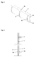
- a cylindrical combustion chamber 1 is bounded radially by a heat exchanger, which has at least one gap 2 for the passage of hot gases.
- An exhaust gas collection chamber 3 is located below a surrounding jacket, not shown, with a connecting piece for an exhaust pipe radially outside the heat exchanger.
- the heat exchanger consists of a plurality of annularly arranged, parallel to the longitudinal axis of the combustion chamber 1 heat exchanger tubes 4, which each form an axially extending gap 2 for the passage of hot gases in the radial direction between two adjacent heat exchanger tubes 4.
- the cross section of the heat exchanger tubes 4 is designed sickle-shaped, wherein each of adjacent heat exchanger tube 4 associated flanks 4a, 4b have an identical inner and outer radius.
- the radially inwardly and outwardly directed surfaces 4c, 4d of the heat exchanger tubes 4 are aligned approximately parallel to one another.
- the gap for the passage of hot gases between two adjacent, associated heat exchanger tubes 4 is formed by a taper of the water-side cross-section.
- the edge 4b tapers between the tube ends on a heat exchanger tube 4.
- beads 5 are introduced, which define the width of the gap 2 and on the opposite surface of the heat exchanger tube 4, there especially on the flank 4a, support.
- FIG. 5 shows a cross section through a heat exchanger tube 4 with a partition wall 6 to divide the water space into an inner combustion chamber near the flow channel 8 and an outer flow channel 9.
- the inner flow channel 8 is provided as a flow channel and the outer flow channel 9 as a return channel.
- beads 7 are formed for receiving the partition wall 6.
Landscapes
- Engineering & Computer Science (AREA)
- Physics & Mathematics (AREA)
- Thermal Sciences (AREA)
- Mechanical Engineering (AREA)
- General Engineering & Computer Science (AREA)
- Geometry (AREA)
- Chemical & Material Sciences (AREA)
- Combustion & Propulsion (AREA)
- Details Of Fluid Heaters (AREA)
- Heat-Exchange Devices With Radiators And Conduit Assemblies (AREA)
- Instantaneous Water Boilers, Portable Hot-Water Supply Apparatuses, And Control Of Portable Hot-Water Supply Apparatuses (AREA)
Applications Claiming Priority (1)
| Application Number | Priority Date | Filing Date | Title |
|---|---|---|---|
| DE200810038041 DE102008038041A1 (de) | 2008-08-16 | 2008-08-16 | Wärmetauscher für ein Heizgerät |
Publications (2)
| Publication Number | Publication Date |
|---|---|
| EP2154444A2 true EP2154444A2 (fr) | 2010-02-17 |
| EP2154444A3 EP2154444A3 (fr) | 2012-06-06 |
Family
ID=41066444
Family Applications (1)
| Application Number | Title | Priority Date | Filing Date |
|---|---|---|---|
| EP09167686A Withdrawn EP2154444A3 (fr) | 2008-08-16 | 2009-08-12 | Echangeur de chaleur pour un appareil de chauffage |
Country Status (2)
| Country | Link |
|---|---|
| EP (1) | EP2154444A3 (fr) |
| DE (1) | DE102008038041A1 (fr) |
Citations (3)
| Publication number | Priority date | Publication date | Assignee | Title |
|---|---|---|---|---|
| DE102004023711B3 (de) | 2004-05-11 | 2005-10-13 | Viessmann Werke Gmbh & Co Kg | Heizgerät |
| DE202005011633U1 (de) | 2005-07-20 | 2006-11-30 | Viessmann Werke Gmbh & Co Kg | Heizgerät |
| DE102006029854A1 (de) | 2006-06-27 | 2008-01-03 | Mhg Heiztechnik Gmbh | Wärmetauscher mit ringförmig ausgebildeten Strömungskanälen |
Family Cites Families (7)
| Publication number | Priority date | Publication date | Assignee | Title |
|---|---|---|---|---|
| FR2487956A1 (fr) * | 1979-11-30 | 1982-02-05 | Saunier Duval | Corps de chauffe pour chaudieres domestiques de chauffage central a eau chaude par le gaz |
| FR2476808A1 (fr) * | 1980-02-22 | 1981-08-28 | Sdecc | Echangeur de chaleur formant barriere anti-deflagration pour chaudieres domestiques de chauffage central |
| EP0050696A1 (fr) * | 1980-10-24 | 1982-05-05 | SAUNIER DUVAL EAU CHAUDE CHAUFFAGE S.D.E.C.C. - Société anonyme | Echangeur de chaleur pour chaudières domestiques de chauffage central |
| EP0745813A3 (fr) * | 1995-05-31 | 1997-12-29 | VIESSMANN WERKE GmbH & CO. | Echangeur de chaleur, en particulier pour chaudière |
| EP0813037A1 (fr) * | 1996-05-31 | 1997-12-17 | VIESSMANN WERKE GmbH & CO. | Echangeur de chaleur, en particulier pour une chaudière |
| CA2211983C (fr) * | 1997-02-28 | 2006-03-14 | Miura Co., Ltd. | Chaudiere a tubes d'eau |
| FR2793313B1 (fr) * | 1999-05-04 | 2001-08-03 | Guillot Ind Sa | Echangeur de chaleur destine a equiper une chaudiere a eau chaude |
-
2008
- 2008-08-16 DE DE200810038041 patent/DE102008038041A1/de not_active Ceased
-
2009
- 2009-08-12 EP EP09167686A patent/EP2154444A3/fr not_active Withdrawn
Patent Citations (3)
| Publication number | Priority date | Publication date | Assignee | Title |
|---|---|---|---|---|
| DE102004023711B3 (de) | 2004-05-11 | 2005-10-13 | Viessmann Werke Gmbh & Co Kg | Heizgerät |
| DE202005011633U1 (de) | 2005-07-20 | 2006-11-30 | Viessmann Werke Gmbh & Co Kg | Heizgerät |
| DE102006029854A1 (de) | 2006-06-27 | 2008-01-03 | Mhg Heiztechnik Gmbh | Wärmetauscher mit ringförmig ausgebildeten Strömungskanälen |
Also Published As
| Publication number | Publication date |
|---|---|
| DE102008038041A1 (de) | 2010-02-25 |
| EP2154444A3 (fr) | 2012-06-06 |
Similar Documents
| Publication | Publication Date | Title |
|---|---|---|
| EP3040638B1 (fr) | Tuyau de transfert de chaleur et chaudiere dotee d'un tel tuyau de transfert de chaleur | |
| EP1979696B1 (fr) | Dispositif de chauffage | |
| WO1992020975A1 (fr) | Appareil de chauffage d'air | |
| DE202007017283U1 (de) | Wärmetauscher mit ringförmig ausgebildeten Strömungskanälen | |
| EP2096372A2 (fr) | Appareil de chauffage | |
| DE102010008175B4 (de) | Wärmeübertrager | |
| EP2192368A2 (fr) | Echangeur thermique | |
| EP2507562A2 (fr) | Appareil de chauffage | |
| EP1899654B1 (fr) | Chaudière de chauffage | |
| DE102004046587B4 (de) | Wärmetauscher | |
| EP2157382A2 (fr) | Appareil de chauffage | |
| DE10123219A1 (de) | Wärmetauscher zum Erwärmen eines Produktes, insbesondere einer Masse zur Herstellung von Süßwaren | |
| DE102008059541A1 (de) | Wärmetauscher | |
| DE202016001143U1 (de) | Abgaswärmetauscher | |
| EP1703227B1 (fr) | Echangeur de chaleur | |
| EP1314947B1 (fr) | Echangeur de chaleur, en particulier pour installation de chauffage | |
| EP2154444A2 (fr) | Echangeur de chaleur pour un appareil de chauffage | |
| EP2290301A2 (fr) | Chaudière à condensation | |
| AT513300B1 (de) | Wärmetauscher | |
| EP2306112A1 (fr) | Appareil de chauffage | |
| DE202008011266U1 (de) | Heizgerät | |
| DE102014015508B4 (de) | Wärmetauscherbausatz | |
| DE29817611U1 (de) | Luftspaltisoliertes Rohrelement | |
| DE102005045098A1 (de) | Kühlvorrichtung für eine Verbrennungskraftmaschine | |
| EP1348914B1 (fr) | Echangeur de chaleur, installation de combustion avec échangeur de chaleur, élément d'obturation pour utilisation dans un tel échangeur de chaleur et méthode de fabrication d'un échangeur de chaleur |
Legal Events
| Date | Code | Title | Description |
|---|---|---|---|
| PUAI | Public reference made under article 153(3) epc to a published international application that has entered the european phase |
Free format text: ORIGINAL CODE: 0009012 |
|
| AK | Designated contracting states |
Kind code of ref document: A2 Designated state(s): AT BE BG CH CY CZ DE DK EE ES FI FR GB GR HR HU IE IS IT LI LT LU LV MC MK MT NL NO PL PT RO SE SI SK SM TR |
|
| AX | Request for extension of the european patent |
Extension state: AL BA RS |
|
| PUAL | Search report despatched |
Free format text: ORIGINAL CODE: 0009013 |
|
| AK | Designated contracting states |
Kind code of ref document: A3 Designated state(s): AT BE BG CH CY CZ DE DK EE ES FI FR GB GR HR HU IE IS IT LI LT LU LV MC MK MT NL NO PL PT RO SE SI SK SM TR |
|
| AX | Request for extension of the european patent |
Extension state: AL BA RS |
|
| RIC1 | Information provided on ipc code assigned before grant |
Ipc: F28F 1/26 20060101ALI20120501BHEP Ipc: F24H 1/40 20060101AFI20120501BHEP Ipc: F28F 1/02 20060101ALI20120501BHEP Ipc: F28D 7/00 20060101ALI20120501BHEP |
|
| 17P | Request for examination filed |
Effective date: 20121206 |
|
| STAA | Information on the status of an ep patent application or granted ep patent |
Free format text: STATUS: THE APPLICATION IS DEEMED TO BE WITHDRAWN |
|
| 18D | Application deemed to be withdrawn |
Effective date: 20121207 |