EP2290301A2 - Chaudière à condensation - Google Patents
Chaudière à condensation Download PDFInfo
- Publication number
- EP2290301A2 EP2290301A2 EP10168443A EP10168443A EP2290301A2 EP 2290301 A2 EP2290301 A2 EP 2290301A2 EP 10168443 A EP10168443 A EP 10168443A EP 10168443 A EP10168443 A EP 10168443A EP 2290301 A2 EP2290301 A2 EP 2290301A2
- Authority
- EP
- European Patent Office
- Prior art keywords
- heat exchanger
- combustion chamber
- condensing boiler
- exchanger tubes
- boiler according
- Prior art date
- Legal status (The legal status is an assumption and is not a legal conclusion. Google has not performed a legal analysis and makes no representation as to the accuracy of the status listed.)
- Withdrawn
Links
Images

Classifications
-
- F—MECHANICAL ENGINEERING; LIGHTING; HEATING; WEAPONS; BLASTING
- F24—HEATING; RANGES; VENTILATING
- F24H—FLUID HEATERS, e.g. WATER OR AIR HEATERS, HAVING HEAT-GENERATING MEANS, e.g. HEAT PUMPS, IN GENERAL
- F24H8/00—Fluid heaters characterised by means for extracting latent heat from flue gases by means of condensation
-
- F—MECHANICAL ENGINEERING; LIGHTING; HEATING; WEAPONS; BLASTING
- F24—HEATING; RANGES; VENTILATING
- F24H—FLUID HEATERS, e.g. WATER OR AIR HEATERS, HAVING HEAT-GENERATING MEANS, e.g. HEAT PUMPS, IN GENERAL
- F24H1/00—Water heaters, e.g. boilers, continuous-flow heaters or water-storage heaters
- F24H1/22—Water heaters other than continuous-flow or water-storage heaters, e.g. water heaters for central heating
- F24H1/24—Water heaters other than continuous-flow or water-storage heaters, e.g. water heaters for central heating with water mantle surrounding the combustion chamber or chambers
- F24H1/26—Water heaters other than continuous-flow or water-storage heaters, e.g. water heaters for central heating with water mantle surrounding the combustion chamber or chambers the water mantle forming an integral body
-
- F—MECHANICAL ENGINEERING; LIGHTING; HEATING; WEAPONS; BLASTING
- F24—HEATING; RANGES; VENTILATING
- F24H—FLUID HEATERS, e.g. WATER OR AIR HEATERS, HAVING HEAT-GENERATING MEANS, e.g. HEAT PUMPS, IN GENERAL
- F24H1/00—Water heaters, e.g. boilers, continuous-flow heaters or water-storage heaters
- F24H1/22—Water heaters other than continuous-flow or water-storage heaters, e.g. water heaters for central heating
- F24H1/40—Water heaters other than continuous-flow or water-storage heaters, e.g. water heaters for central heating with water tube or tubes
- F24H1/403—Water heaters other than continuous-flow or water-storage heaters, e.g. water heaters for central heating with water tube or tubes the water tubes being arranged in one or more circles around the burner
-
- F—MECHANICAL ENGINEERING; LIGHTING; HEATING; WEAPONS; BLASTING
- F24—HEATING; RANGES; VENTILATING
- F24H—FLUID HEATERS, e.g. WATER OR AIR HEATERS, HAVING HEAT-GENERATING MEANS, e.g. HEAT PUMPS, IN GENERAL
- F24H1/00—Water heaters, e.g. boilers, continuous-flow heaters or water-storage heaters
- F24H1/22—Water heaters other than continuous-flow or water-storage heaters, e.g. water heaters for central heating
- F24H1/44—Water heaters other than continuous-flow or water-storage heaters, e.g. water heaters for central heating with combinations of two or more of the types covered by groups F24H1/24 - F24H1/40
-
- F—MECHANICAL ENGINEERING; LIGHTING; HEATING; WEAPONS; BLASTING
- F24—HEATING; RANGES; VENTILATING
- F24H—FLUID HEATERS, e.g. WATER OR AIR HEATERS, HAVING HEAT-GENERATING MEANS, e.g. HEAT PUMPS, IN GENERAL
- F24H9/00—Details
- F24H9/0005—Details for water heaters
- F24H9/001—Guiding means
- F24H9/0015—Guiding means in water channels
-
- F—MECHANICAL ENGINEERING; LIGHTING; HEATING; WEAPONS; BLASTING
- F28—HEAT EXCHANGE IN GENERAL
- F28D—HEAT-EXCHANGE APPARATUS, NOT PROVIDED FOR IN ANOTHER SUBCLASS, IN WHICH THE HEAT-EXCHANGE MEDIA DO NOT COME INTO DIRECT CONTACT
- F28D7/00—Heat-exchange apparatus having stationary tubular conduit assemblies for both heat-exchange media, the media being in contact with different sides of a conduit wall
- F28D7/0066—Multi-circuit heat-exchangers, e.g. integrating different heat exchange sections in the same unit or heat-exchangers for more than two fluids
- F28D7/0075—Multi-circuit heat-exchangers, e.g. integrating different heat exchange sections in the same unit or heat-exchangers for more than two fluids with particular circuits for the same heat exchange medium, e.g. with the same heat exchange medium flowing through sections having different heat exchange capacities or for heating or cooling the same heat exchange medium at different temperatures
-
- F—MECHANICAL ENGINEERING; LIGHTING; HEATING; WEAPONS; BLASTING
- F28—HEAT EXCHANGE IN GENERAL
- F28D—HEAT-EXCHANGE APPARATUS, NOT PROVIDED FOR IN ANOTHER SUBCLASS, IN WHICH THE HEAT-EXCHANGE MEDIA DO NOT COME INTO DIRECT CONTACT
- F28D7/00—Heat-exchange apparatus having stationary tubular conduit assemblies for both heat-exchange media, the media being in contact with different sides of a conduit wall
- F28D7/16—Heat-exchange apparatus having stationary tubular conduit assemblies for both heat-exchange media, the media being in contact with different sides of a conduit wall the conduits being arranged in parallel spaced relation
- F28D7/163—Heat-exchange apparatus having stationary tubular conduit assemblies for both heat-exchange media, the media being in contact with different sides of a conduit wall the conduits being arranged in parallel spaced relation with conduit assemblies having a particular shape, e.g. square or annular; with assemblies of conduits having different geometrical features; with multiple groups of conduits connected in series or parallel and arranged inside common casing
- F28D7/1669—Heat-exchange apparatus having stationary tubular conduit assemblies for both heat-exchange media, the media being in contact with different sides of a conduit wall the conduits being arranged in parallel spaced relation with conduit assemblies having a particular shape, e.g. square or annular; with assemblies of conduits having different geometrical features; with multiple groups of conduits connected in series or parallel and arranged inside common casing the conduit assemblies having an annular shape; the conduits being assembled around a central distribution tube
-
- F—MECHANICAL ENGINEERING; LIGHTING; HEATING; WEAPONS; BLASTING
- F28—HEAT EXCHANGE IN GENERAL
- F28D—HEAT-EXCHANGE APPARATUS, NOT PROVIDED FOR IN ANOTHER SUBCLASS, IN WHICH THE HEAT-EXCHANGE MEDIA DO NOT COME INTO DIRECT CONTACT
- F28D7/00—Heat-exchange apparatus having stationary tubular conduit assemblies for both heat-exchange media, the media being in contact with different sides of a conduit wall
- F28D7/16—Heat-exchange apparatus having stationary tubular conduit assemblies for both heat-exchange media, the media being in contact with different sides of a conduit wall the conduits being arranged in parallel spaced relation
- F28D7/1684—Heat-exchange apparatus having stationary tubular conduit assemblies for both heat-exchange media, the media being in contact with different sides of a conduit wall the conduits being arranged in parallel spaced relation the conduits having a non-circular cross-section
-
- F—MECHANICAL ENGINEERING; LIGHTING; HEATING; WEAPONS; BLASTING
- F28—HEAT EXCHANGE IN GENERAL
- F28F—DETAILS OF HEAT-EXCHANGE AND HEAT-TRANSFER APPARATUS, OF GENERAL APPLICATION
- F28F2255/00—Heat exchanger elements made of materials having special features or resulting from particular manufacturing processes
- F28F2255/16—Heat exchanger elements made of materials having special features or resulting from particular manufacturing processes extruded
-
- Y—GENERAL TAGGING OF NEW TECHNOLOGICAL DEVELOPMENTS; GENERAL TAGGING OF CROSS-SECTIONAL TECHNOLOGIES SPANNING OVER SEVERAL SECTIONS OF THE IPC; TECHNICAL SUBJECTS COVERED BY FORMER USPC CROSS-REFERENCE ART COLLECTIONS [XRACs] AND DIGESTS
- Y02—TECHNOLOGIES OR APPLICATIONS FOR MITIGATION OR ADAPTATION AGAINST CLIMATE CHANGE
- Y02B—CLIMATE CHANGE MITIGATION TECHNOLOGIES RELATED TO BUILDINGS, e.g. HOUSING, HOUSE APPLIANCES OR RELATED END-USER APPLICATIONS
- Y02B30/00—Energy efficient heating, ventilation or air conditioning [HVAC]
Definitions
- the invention relates to a condensing boiler according to the preamble of claim 1.
- Generic condensing boilers are fired with a gas or oil burner and have a cylindrical combustion chamber, which is usually limited in known devices radially from a helically coiled heat exchanger. At least one gap between the tube coils for the passage of the hot gases represents the actual heat exchanger surface. Also common are a front cover element for receiving the burner, a rear cover element as a closure for the combustion chamber, supply and return connection and an exhaust gas collection chamber, which radially outside the heat exchanger arranged under a surrounding jacket and provided with a connection piece for an exhaust pipe.
- the heating water-side flow guide is a forced-flow heat exchanger.
- a circulation pump ensures a given water volume flow through the mostly relatively narrow water channels. In this way, despite high water content, it is possible to realize quite high heat flow densities entered at the hot gas side.
- a heater with two helically coiled heat exchangers is known, which are screwed into one another and parallel to each other by a heating medium can be flowed through.
- the juxtaposed coil ends are connected to each other and have a common connection piece.
- the supply and return connections are located on opposite ends of the heat exchanger.
- the DE 10 2004 023 711 B3 also shows a heater with a helically coiled heat exchanger and at least two hydraulically interconnected coil areas. These are formed differently in diameter and can be arranged helically rotated into each other. The exhaust gas thus flows first through the gaps of the inner coil and then over a gap further through the gaps in the outer coil. Because even in this embodiment, a one-piece tube, In particular square tube, is used, it is production technology hardly possible to influence the gap geometry. Furthermore, from the DE 10 2006 029 854 A1 a heat exchanger with annular flow channels known. Here several identical annular segments are combined vertically and parallel to each other to form a heat exchanger.
- the invention has for its object to optimize a condensing boiler, especially with regard to the most compact dimensions and good heat transfer properties.
- the condensing boiler is characterized in that the combustion chamber is arranged approximately horizontally and is delimited, at least in the lower and in the lateral regions, by a plurality of heat exchanger tubes, parallel to the longitudinal axis of the combustion chamber, of a first heat exchanger stage. These each form between two adjacent heat exchanger tubes an axially extending gap for the passage of hot gases in the radial direction in a first exhaust gas collection chamber. Below the first combustor near heat exchanger tubes, a second arrangement is provided with heat exchanger tubes as the second heat exchanger stage, so that the hot gases flow from the first exhaust plenum through the axially extending column of the second heat exchanger stage and then get into a second exhaust plenum with a connecting piece for an exhaust pipe.
- All heat exchanger tubes each have the same geometry and the overall arrangement is symmetrical to the vertical longitudinal axis.
- the heat exchanger tubes are arranged so that each between two adjacent heat exchanger tubes In any case resulting gap has a slope outwards and / or down to divert condensate water from the combustion chamber and / or a gap to the outside in one of the exhaust plenums.
- the heat exchanger tubes consist of extruded profiles with a substantially rectangular cross-section, optionally with inlet and / or outlet-side radii or curves.
- the heat exchanger tubes of the first heat exchanger stage define the lower half of the combustion chamber and are arranged symmetrically to the vertical center axis of the combustion chamber. In this case, the outside of each last heat exchanger tube is located on both sides on or just below the horizontal center axis of the combustion chamber.
- the cross section of the heat exchanger tubes is designed sickle-shaped.
- the flanks assigned to an adjacent heat exchanger tube have an identical inner and outer radius.
- the radially inwardly and outwardly directed surfaces of the heat exchanger tubes are aligned parallel or approximately parallel to each other.
- the water-side connection of the heat exchanger tubes is in each case the front side, via a connection to the front and rear cover element.
- flanks of a heat exchanger tube preferably beads and / or cams are introduced as the gap defining surfaces which define the width of the gap and are supported on each other and / or on the opposite surface.
- the crescent-shaped heat exchanger tubes are arranged mirror-symmetrically on both half sides of the central axis.
- the symmetry plane is vertical.
- a longitudinally symmetrical equalizing tube is arranged in the first and second heat exchanger stage. This is adapted on both longitudinal sides of the mirror-symmetrical geometries of the crescent-shaped heat exchanger tubes and forms with the respectively associated adjacent heat exchanger tube an axially extending gap for the passage of hot gases. It is also flowed through by water.
- the return water flows, starting from the return connection piece in the lower region, in parallel through all heat exchanger tubes of the second heat exchanger stage and is deflected at the opposite end of the arrangement upwards. It then flows in parallel through all the heat exchanger tubes of the first heat exchanger stage, is again after deflected above and passes above the combustion chamber to the supply connection in the upper part of the arrangement.
- an approximately horizontally extending and the combustion chamber upwardly delimiting shaft is arranged above the combustion chamber.
- preheated water exits after exiting the heat exchanger tubes of the first heat exchanger stage, on the lid member for receiving the burner opposite side, frontally and through a flow connection piece on the top of the shaft, in particular in the burner area.
- the combustion chamber upwardly delimiting shaft may optionally have a rectangular, trapezoidal, roof-like, upwardly curved or approximately semicircular cross-section.
- It preferably extends with its two downwardly directed longitudinal sides to approximately in the outer edge regions of the respective upper heat exchanger tubes of the first heat exchanger stage, so that in each case between the underside of the shaft and the top of the last or adjacent heat exchanger tube, a gap for the passage of hot gases is formed outside.
- a supplemental embodiment provides that the combustion chamber leading upwards limiting water leading shaft is divided in the region of its two downwardly directed longitudinal sides with a longitudinal partition wall. As a result, in each case a further channel with a smaller cross section than the remaining remaining cross section is formed in the two lateral edge regions.
- the two channels can be traversed in the lateral region of the shaft parallel to the first heat exchanger stage. The water is then deflected and flows through the remaining, upper portion of the shaft in the direction of the flow connection piece.
- the two channels in the lateral region of the shaft opposite to the first heat exchanger stage and thus as well as the rest of the shaft in the direction of the flow connection piece can be flowed through.
- the channels and / or their inlet and / or outlet regions are preferably designed such that the flow velocity in the channels is higher than in the remaining region of the shaft in order, for example, to achieve intensive cooling of the edge regions.
- the return connection piece is advantageously arranged on the end face opposite the cover element for receiving the burner, preferably relatively far below, approximately at the level of the second heat exchanger stage.
- the inventive design results in a condensing boiler with very compact dimensions and good heat transfer properties.
- the overall structure with the same heat exchanger tubes offers not only the advantage of simple production but also variable cover different lengths for different combustion and heat exchanger performance. It is also possible to vary the size of the firebox as well as the heat transfer capacity over the number of tubes and thus the pitch circle diameter. Nevertheless, then all heat exchanger tubes used remain the same, and variants arise only with different cover elements, which can then be connected with the same attachments or components.
- heat exchanger tubes offer a variety of design options. It can, for example, an aluminum extruded section be used as an endless tube profile, which after cutting to length of a heat exchanger tube this must then be provided at the ends with a corresponding expansion, so that the gap results in the central region. Furthermore, hydroforming methods for producing the heat exchanger tubes are suitable. Also, stainless steel can be used as a pipe material. As a joining method for heat exchanger tubes, cover elements and / or water-carrying parts, welding, soldering and gluing are suitable.
- the heat exchanger tubes are respectively frontally connected to the front and rear cover element and connected there water side.
- the gap for the passage of hot gases between two adjacent, associated heat exchanger tubes is formed by a taper of the water-side cross section in the region of the flanks between the tube ends. This taper can be formed on sickle-shaped tubes on the flank with inner radius, on the flank with outer radius and / or on both flanks.
- the gap for the passage of hot gases has a width in the range of about 1 mm to 2 mm.
- the gap for the passage of hot gases may have a constant width over the entire flow path in the radial direction. Alternatively, it is also possible that its width decreases from the inside to the outside and is thereby adapted to the volume of heating gas which decreases with the cooling.
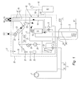
- the condensing boiler consists essentially of a combustion chamber 1 with a front cover element 2, shown here as a water-cooled burner door, for receiving a burner, and a rear cover element 3 as a closure for the combustion chamber 1, which is mainly limited by a heat exchanger through which flows through water.
- This has column 4 for the passage of hot gases.
- a return connection piece 5 in the lower region on the lid member 2 for receiving the burner opposite end face and a flow connection piece 6 in the upper region of the arrangement.
- the combustion chamber 1 is arranged approximately horizontally and is bounded in the lower half by a plurality of heat exchanger tubes 7, which are parallel to the longitudinal axis of the combustion chamber 1, of a first heat exchanger stage A.
- a first heat exchanger stage A In each case between two adjacent heat exchanger tubes 7 are axially extending column 4 for the passage of hot gases in radial direction in a first exhaust gas collection chamber 8 available.
- the heat exchanger tubes of the first heat exchanger stage A define the lower half of the combustion chamber 1 and are arranged symmetrically to the vertical center axis of the combustion chamber 1.
- a second arrangement with heat exchanger tubes 7 is provided as a second heat exchanger stage B, so that the hot gases from the first exhaust gas collection chamber 8 through the axially extending column of the second heat exchanger stage B and then into a second exhaust gas collecting chamber 9 with a connecting piece 10 for a Get exhaust pipe.
- All heat exchanger tubes 7 each have the same geometry, are symmetrical in the overall arrangement to the vertical longitudinal axis, each end face connected to the front and rear cover element 3, and connected there water side.
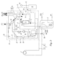
- the heat exchanger tubes 7 according to the Fig. 1 . 2 and 3 a substantially rectangular cross-section with inlet and / or exit side radii or are, as in Fig. 4 shown, provided with a crescent-shaped cross-section.
- each of the adjacent heat exchanger tube 7 'associated flanks have an identical inner and outer radius and the crescent-shaped heat exchanger tubes 7' on both half sides of the central axis are arranged mirror-symmetrically to each other. Therefore, according to Fig.
- the flow through the condensing boiler is independent of the selected pipe geometry.
- the return water flows in all variants shown, starting from the return connection pipe 5 in the lower region, parallel through all the heat exchanger tubes 7, 7 'of the second heat exchanger stage B, is deflected at the opposite end of the arrangement upwards and then flows parallel through all heat exchanger tubes 7, 7' the first heat exchanger stage A. Thereafter, a new deflection follows upwards, before the heated water above the combustion chamber 1 at the flow connection 4 leaves the water space.
- an approximately horizontally extending and the combustion chamber 1 upwardly with its semi-circular shape limiting shaft 12 is arranged, which is traversed by spaced reinforcing ribs 13. These are permeable to designed the flow of water, as drawn by way of example with openings.
- the shaft 12 enters preheated water after exiting the heat exchanger tubes 7, 7 'of the first heat exchanger stage A, on the lid member 2 for receiving the burner opposite side, frontally and through the flow connection 4 on the top of the shaft 12 in the burner near Area again.
- Fig. 3 and Fig. 4 extends the shaft 12 with its two downwardly directed longitudinal sides into the outer edge regions of the respective upper heat exchanger tubes 7, 7 'of the first heat exchanger stage A, wherein the structure with the inclined heat exchanger tubes 7' according to Fig. 4 shows a slightly shortened shaft 12, because the heat exchanger tubes 7 'rich because of shape and arrangement to above the horizontal center axis of the combustion chamber 1. Furthermore, the combustion chamber 1 upwardly limiting water leading shaft 12 according to Fig. 4 divided in the region of its two downwardly directed longitudinal sides with a longitudinally extending partition wall 14 so that in each case a further channel 15 is formed with a smaller cross section than the remaining remaining cross section of the shaft 12 in the two edge regions. The two channels 15 are flowed through either parallel or opposite to the first heat exchanger stage A.
Landscapes
- Engineering & Computer Science (AREA)
- Physics & Mathematics (AREA)
- Thermal Sciences (AREA)
- Mechanical Engineering (AREA)
- General Engineering & Computer Science (AREA)
- Chemical & Material Sciences (AREA)
- Combustion & Propulsion (AREA)
- Geometry (AREA)
- Details Of Fluid Heaters (AREA)
- Heat-Exchange Devices With Radiators And Conduit Assemblies (AREA)
Applications Claiming Priority (1)
| Application Number | Priority Date | Filing Date | Title |
|---|---|---|---|
| DE102009032121A DE102009032121A1 (de) | 2009-07-08 | 2009-07-08 | Brennwertkessel |
Publications (2)
| Publication Number | Publication Date |
|---|---|
| EP2290301A2 true EP2290301A2 (fr) | 2011-03-02 |
| EP2290301A3 EP2290301A3 (fr) | 2016-03-09 |
Family
ID=42668469
Family Applications (1)
| Application Number | Title | Priority Date | Filing Date |
|---|---|---|---|
| EP10168443.9A Withdrawn EP2290301A3 (fr) | 2009-07-08 | 2010-07-05 | Chaudière à condensation |
Country Status (2)
| Country | Link |
|---|---|
| EP (1) | EP2290301A3 (fr) |
| DE (1) | DE102009032121A1 (fr) |
Cited By (2)
| Publication number | Priority date | Publication date | Assignee | Title |
|---|---|---|---|---|
| CN105571132A (zh) * | 2016-02-05 | 2016-05-11 | 上海工业锅炉研究所 | 一种立式自然循环冷凝锅炉 |
| CN108180772A (zh) * | 2017-12-30 | 2018-06-19 | 华帝股份有限公司 | 一种换热体 |
Citations (3)
| Publication number | Priority date | Publication date | Assignee | Title |
|---|---|---|---|---|
| DE102004023711B3 (de) | 2004-05-11 | 2005-10-13 | Viessmann Werke Gmbh & Co Kg | Heizgerät |
| DE202005011633U1 (de) | 2005-07-20 | 2006-11-30 | Viessmann Werke Gmbh & Co Kg | Heizgerät |
| DE102006029854A1 (de) | 2006-06-27 | 2008-01-03 | Mhg Heiztechnik Gmbh | Wärmetauscher mit ringförmig ausgebildeten Strömungskanälen |
Family Cites Families (3)
| Publication number | Priority date | Publication date | Assignee | Title |
|---|---|---|---|---|
| GB9012032D0 (en) * | 1990-05-30 | 1990-07-18 | Stelrad Group Ltd | Hot water boilers |
| DE29602990U1 (de) * | 1995-02-06 | 1996-04-04 | Joh. Vaillant Gmbh U. Co, 42859 Remscheid | Wasserheizer |
| DE10244342A1 (de) * | 2002-09-24 | 2004-04-01 | Robert Bosch Gmbh | Brennwert-Heizgerät |
-
2009
- 2009-07-08 DE DE102009032121A patent/DE102009032121A1/de not_active Ceased
-
2010
- 2010-07-05 EP EP10168443.9A patent/EP2290301A3/fr not_active Withdrawn
Patent Citations (3)
| Publication number | Priority date | Publication date | Assignee | Title |
|---|---|---|---|---|
| DE102004023711B3 (de) | 2004-05-11 | 2005-10-13 | Viessmann Werke Gmbh & Co Kg | Heizgerät |
| DE202005011633U1 (de) | 2005-07-20 | 2006-11-30 | Viessmann Werke Gmbh & Co Kg | Heizgerät |
| DE102006029854A1 (de) | 2006-06-27 | 2008-01-03 | Mhg Heiztechnik Gmbh | Wärmetauscher mit ringförmig ausgebildeten Strömungskanälen |
Cited By (3)
| Publication number | Priority date | Publication date | Assignee | Title |
|---|---|---|---|---|
| CN105571132A (zh) * | 2016-02-05 | 2016-05-11 | 上海工业锅炉研究所 | 一种立式自然循环冷凝锅炉 |
| CN105571132B (zh) * | 2016-02-05 | 2018-08-31 | 上海工业锅炉研究所有限公司 | 一种立式自然循环冷凝锅炉 |
| CN108180772A (zh) * | 2017-12-30 | 2018-06-19 | 华帝股份有限公司 | 一种换热体 |
Also Published As
| Publication number | Publication date |
|---|---|
| EP2290301A3 (fr) | 2016-03-09 |
| DE102009032121A1 (de) | 2011-01-13 |
Similar Documents
| Publication | Publication Date | Title |
|---|---|---|
| EP2440855B1 (fr) | Chaudière sectionnée | |
| WO2009010834A1 (fr) | Échangeur thermique | |
| EP2096372A2 (fr) | Appareil de chauffage | |
| EP2507562A2 (fr) | Appareil de chauffage | |
| EP2313698B1 (fr) | Chaudière sectionnée en fonte ou en aluminium | |
| EP2157382A2 (fr) | Appareil de chauffage | |
| EP2290301A2 (fr) | Chaudière à condensation | |
| EP0128463A2 (fr) | Appareil de chauffage des locaux pour des locaux de petite dimension | |
| EP1278025A2 (fr) | Echangeur de chaleur pour chaudière à gaz, esp. chaudière à condensation | |
| DE3238603C2 (fr) | ||
| WO2010139662A2 (fr) | Chaudière sectionnée | |
| AT12668U1 (de) | Wärmetauscher für den rauchgaskanal einer feuerung | |
| EP0177904A2 (fr) | Dispositif pour l'échange de chaleur entre deux gaz en flux croisé | |
| DE102012008183B4 (de) | Wärmetauscherbausatz | |
| EP1602886B1 (fr) | Chaudière | |
| EP0816776B1 (fr) | Chauffe-eau à gaz et chambre de combustion refroidie par eau | |
| WO2017102490A1 (fr) | Ensemble échangeur de chaleur primaire | |
| EP0618410A2 (fr) | Echangeur de chaleur pour chaudière à condensation | |
| EP2154444A2 (fr) | Echangeur de chaleur pour un appareil de chauffage | |
| DE102014015508B4 (de) | Wärmetauscherbausatz | |
| AT412913B (de) | Wendelförmiger wärmeaustauscher | |
| DE10334754A1 (de) | Rippenwendel-Wärmeübertrager | |
| DE10341644A1 (de) | Wendelförmiger Wärmeaustauscher | |
| DE10244342A1 (de) | Brennwert-Heizgerät | |
| CH666954A5 (de) | Brennwert-heizkessel. |
Legal Events
| Date | Code | Title | Description |
|---|---|---|---|
| PUAI | Public reference made under article 153(3) epc to a published international application that has entered the european phase |
Free format text: ORIGINAL CODE: 0009012 |
|
| AK | Designated contracting states |
Kind code of ref document: A2 Designated state(s): AL AT BE BG CH CY CZ DE DK EE ES FI FR GB GR HR HU IE IS IT LI LT LU LV MC MK MT NL NO PL PT RO SE SI SK SM TR |
|
| AX | Request for extension of the european patent |
Extension state: BA ME RS |
|
| PUAL | Search report despatched |
Free format text: ORIGINAL CODE: 0009013 |
|
| RAP1 | Party data changed (applicant data changed or rights of an application transferred) |
Owner name: ROBERT BOSCH GMBH |
|
| AK | Designated contracting states |
Kind code of ref document: A3 Designated state(s): AL AT BE BG CH CY CZ DE DK EE ES FI FR GB GR HR HU IE IS IT LI LT LU LV MC MK MT NL NO PL PT RO SE SI SK SM TR |
|
| AX | Request for extension of the european patent |
Extension state: BA ME RS |
|
| RIC1 | Information provided on ipc code assigned before grant |
Ipc: F24H 1/44 20060101ALI20160201BHEP Ipc: F28D 21/00 20060101ALI20160201BHEP Ipc: F24H 1/26 20060101ALI20160201BHEP Ipc: F28D 7/00 20060101ALI20160201BHEP Ipc: F24H 9/00 20060101ALI20160201BHEP Ipc: F24H 8/00 20060101AFI20160201BHEP Ipc: F24H 1/40 20060101ALI20160201BHEP |
|
| STAA | Information on the status of an ep patent application or granted ep patent |
Free format text: STATUS: THE APPLICATION IS DEEMED TO BE WITHDRAWN |
|
| 18D | Application deemed to be withdrawn |
Effective date: 20160910 |