EP2154461A1 - Dispositif caloduc en boucle a temperature uniforme - Google Patents
Dispositif caloduc en boucle a temperature uniforme Download PDFInfo
- Publication number
- EP2154461A1 EP2154461A1 EP08748456A EP08748456A EP2154461A1 EP 2154461 A1 EP2154461 A1 EP 2154461A1 EP 08748456 A EP08748456 A EP 08748456A EP 08748456 A EP08748456 A EP 08748456A EP 2154461 A1 EP2154461 A1 EP 2154461A1
- Authority
- EP
- European Patent Office
- Prior art keywords
- vapor chamber
- condensing
- heat pipe
- fins
- loop heat
- Prior art date
- Legal status (The legal status is an assumption and is not a legal conclusion. Google has not performed a legal analysis and makes no representation as to the accuracy of the status listed.)
- Withdrawn
Links
Images

Classifications
-
- F—MECHANICAL ENGINEERING; LIGHTING; HEATING; WEAPONS; BLASTING
- F28—HEAT EXCHANGE IN GENERAL
- F28D—HEAT-EXCHANGE APPARATUS, NOT PROVIDED FOR IN ANOTHER SUBCLASS, IN WHICH THE HEAT-EXCHANGE MEDIA DO NOT COME INTO DIRECT CONTACT
- F28D15/00—Heat-exchange apparatus with the intermediate heat-transfer medium in closed tubes passing into or through the conduit walls ; Heat-exchange apparatus employing intermediate heat-transfer medium or bodies
- F28D15/02—Heat-exchange apparatus with the intermediate heat-transfer medium in closed tubes passing into or through the conduit walls ; Heat-exchange apparatus employing intermediate heat-transfer medium or bodies in which the medium condenses and evaporates, e.g. heat pipes
- F28D15/0266—Heat-exchange apparatus with the intermediate heat-transfer medium in closed tubes passing into or through the conduit walls ; Heat-exchange apparatus employing intermediate heat-transfer medium or bodies in which the medium condenses and evaporates, e.g. heat pipes with separate evaporating and condensing chambers connected by at least one conduit; Loop-type heat pipes; with multiple or common evaporating or condensing chambers
-
- F—MECHANICAL ENGINEERING; LIGHTING; HEATING; WEAPONS; BLASTING
- F28—HEAT EXCHANGE IN GENERAL
- F28D—HEAT-EXCHANGE APPARATUS, NOT PROVIDED FOR IN ANOTHER SUBCLASS, IN WHICH THE HEAT-EXCHANGE MEDIA DO NOT COME INTO DIRECT CONTACT
- F28D15/00—Heat-exchange apparatus with the intermediate heat-transfer medium in closed tubes passing into or through the conduit walls ; Heat-exchange apparatus employing intermediate heat-transfer medium or bodies
- F28D15/02—Heat-exchange apparatus with the intermediate heat-transfer medium in closed tubes passing into or through the conduit walls ; Heat-exchange apparatus employing intermediate heat-transfer medium or bodies in which the medium condenses and evaporates, e.g. heat pipes
- F28D15/04—Heat-exchange apparatus with the intermediate heat-transfer medium in closed tubes passing into or through the conduit walls ; Heat-exchange apparatus employing intermediate heat-transfer medium or bodies in which the medium condenses and evaporates, e.g. heat pipes with tubes having a capillary structure
- F28D15/043—Heat-exchange apparatus with the intermediate heat-transfer medium in closed tubes passing into or through the conduit walls ; Heat-exchange apparatus employing intermediate heat-transfer medium or bodies in which the medium condenses and evaporates, e.g. heat pipes with tubes having a capillary structure forming loops, e.g. capillary pumped loops
-
- F—MECHANICAL ENGINEERING; LIGHTING; HEATING; WEAPONS; BLASTING
- F28—HEAT EXCHANGE IN GENERAL
- F28D—HEAT-EXCHANGE APPARATUS, NOT PROVIDED FOR IN ANOTHER SUBCLASS, IN WHICH THE HEAT-EXCHANGE MEDIA DO NOT COME INTO DIRECT CONTACT
- F28D15/00—Heat-exchange apparatus with the intermediate heat-transfer medium in closed tubes passing into or through the conduit walls ; Heat-exchange apparatus employing intermediate heat-transfer medium or bodies
- F28D15/02—Heat-exchange apparatus with the intermediate heat-transfer medium in closed tubes passing into or through the conduit walls ; Heat-exchange apparatus employing intermediate heat-transfer medium or bodies in which the medium condenses and evaporates, e.g. heat pipes
- F28D15/04—Heat-exchange apparatus with the intermediate heat-transfer medium in closed tubes passing into or through the conduit walls ; Heat-exchange apparatus employing intermediate heat-transfer medium or bodies in which the medium condenses and evaporates, e.g. heat pipes with tubes having a capillary structure
- F28D15/046—Heat-exchange apparatus with the intermediate heat-transfer medium in closed tubes passing into or through the conduit walls ; Heat-exchange apparatus employing intermediate heat-transfer medium or bodies in which the medium condenses and evaporates, e.g. heat pipes with tubes having a capillary structure characterised by the material or the construction of the capillary structure
-
- F—MECHANICAL ENGINEERING; LIGHTING; HEATING; WEAPONS; BLASTING
- F28—HEAT EXCHANGE IN GENERAL
- F28D—HEAT-EXCHANGE APPARATUS, NOT PROVIDED FOR IN ANOTHER SUBCLASS, IN WHICH THE HEAT-EXCHANGE MEDIA DO NOT COME INTO DIRECT CONTACT
- F28D15/00—Heat-exchange apparatus with the intermediate heat-transfer medium in closed tubes passing into or through the conduit walls ; Heat-exchange apparatus employing intermediate heat-transfer medium or bodies
- F28D15/02—Heat-exchange apparatus with the intermediate heat-transfer medium in closed tubes passing into or through the conduit walls ; Heat-exchange apparatus employing intermediate heat-transfer medium or bodies in which the medium condenses and evaporates, e.g. heat pipes
- F28D15/06—Control arrangements therefor
-
- F—MECHANICAL ENGINEERING; LIGHTING; HEATING; WEAPONS; BLASTING
- F28—HEAT EXCHANGE IN GENERAL
- F28F—DETAILS OF HEAT-EXCHANGE AND HEAT-TRANSFER APPARATUS, OF GENERAL APPLICATION
- F28F13/00—Arrangements for modifying heat-transfer, e.g. increasing, decreasing
-
- H—ELECTRICITY
- H10—SEMICONDUCTOR DEVICES; ELECTRIC SOLID-STATE DEVICES NOT OTHERWISE PROVIDED FOR
- H10W—GENERIC PACKAGES, INTERCONNECTIONS, CONNECTORS OR OTHER CONSTRUCTIONAL DETAILS OF DEVICES COVERED BY CLASS H10
- H10W40/00—Arrangements for thermal protection or thermal control
- H10W40/70—Fillings or auxiliary members in containers or in encapsulations for thermal protection or control
- H10W40/73—Fillings or auxiliary members in containers or in encapsulations for thermal protection or control for cooling by change of state
-
- F—MECHANICAL ENGINEERING; LIGHTING; HEATING; WEAPONS; BLASTING
- F28—HEAT EXCHANGE IN GENERAL
- F28F—DETAILS OF HEAT-EXCHANGE AND HEAT-TRANSFER APPARATUS, OF GENERAL APPLICATION
- F28F1/00—Tubular elements; Assemblies of tubular elements
- F28F1/10—Tubular elements and assemblies thereof with means for increasing heat-transfer area, e.g. with fins, with projections, with recesses
- F28F1/12—Tubular elements and assemblies thereof with means for increasing heat-transfer area, e.g. with fins, with projections, with recesses the means being only outside the tubular element
- F28F1/124—Tubular elements and assemblies thereof with means for increasing heat-transfer area, e.g. with fins, with projections, with recesses the means being only outside the tubular element and being formed of pins
-
- F—MECHANICAL ENGINEERING; LIGHTING; HEATING; WEAPONS; BLASTING
- F28—HEAT EXCHANGE IN GENERAL
- F28F—DETAILS OF HEAT-EXCHANGE AND HEAT-TRANSFER APPARATUS, OF GENERAL APPLICATION
- F28F1/00—Tubular elements; Assemblies of tubular elements
- F28F1/10—Tubular elements and assemblies thereof with means for increasing heat-transfer area, e.g. with fins, with projections, with recesses
- F28F1/12—Tubular elements and assemblies thereof with means for increasing heat-transfer area, e.g. with fins, with projections, with recesses the means being only outside the tubular element
- F28F1/14—Tubular elements and assemblies thereof with means for increasing heat-transfer area, e.g. with fins, with projections, with recesses the means being only outside the tubular element and extending longitudinally
- F28F1/20—Tubular elements and assemblies thereof with means for increasing heat-transfer area, e.g. with fins, with projections, with recesses the means being only outside the tubular element and extending longitudinally the means being attachable to the element
-
- F—MECHANICAL ENGINEERING; LIGHTING; HEATING; WEAPONS; BLASTING
- F28—HEAT EXCHANGE IN GENERAL
- F28F—DETAILS OF HEAT-EXCHANGE AND HEAT-TRANSFER APPARATUS, OF GENERAL APPLICATION
- F28F1/00—Tubular elements; Assemblies of tubular elements
- F28F1/10—Tubular elements and assemblies thereof with means for increasing heat-transfer area, e.g. with fins, with projections, with recesses
- F28F1/12—Tubular elements and assemblies thereof with means for increasing heat-transfer area, e.g. with fins, with projections, with recesses the means being only outside the tubular element
- F28F1/24—Tubular elements and assemblies thereof with means for increasing heat-transfer area, e.g. with fins, with projections, with recesses the means being only outside the tubular element and extending transversely
- F28F1/30—Tubular elements and assemblies thereof with means for increasing heat-transfer area, e.g. with fins, with projections, with recesses the means being only outside the tubular element and extending transversely the means being attachable to the element
Definitions
- the present invention relates to the general heat transfer and electronic cooling field, and more particularly to a heat transfer device combined a flatten loop heat pipe and a vapor chamber.
- Loop heat pipe is a new type of two-phase high efficient heat transfer device, which is driven by the capillary force from the wick material, and inside which the heat is transferred by phase change, therefore the loop heat pipe can transfer large heat from a long distance with small temperature difference.
- the evaporator of the loop heat pipe locates on the heat source, and with a primary wick inside it.
- the compensation chamber is connected with the evaporator by a secondary wick.
- the condenser is attached on a heat sink.
- the evaporator and the condenser pipe are connected by the vapor pipe, and the condenser pipe and the compensation chamber are connected by the liquid pipe.
- the wick will dry out when the mass flow rate of evaporation is larger than that of returning. Besides, the large thermal conductivity of the wick leads to the large heat leak from the evaporator to the compensation chamber, results in high temperature in the compensation chamber and then high operation temperature of the loop heat pipe.
- a Chinese patent named High Efficient Flatten Loop Heat Pipe (No. 200510035406.4 ) reveals a flatten loop heat pipe, which comprising two wicks, the primary wick for evaporation and the secondary wick for compensation.
- the primary wick consists horizontal and vertical grooves, which are advanced for evaporation, and the vapor can flow via the grooves with a lower pressure drop, leads to a lower total pressure drop of the loop and a better performance of the loop.
- the purpose of this invention is to overcome the disadvantages of the existing loop heat pipes, and invent a new device combined a flatten loop heat pipe and a vapor chamber for high heat flux chips cooling.
- temperature control fins can be located into the heat transfer device combined a flatten loop heat pipe and a vapor chamber.
- the condenser of the heat transfer device combined a flatten loop heat pipe and a vapor chamber can comprise a condensing clip ring and condensing fins, where the condensing fins locate on the outside surface of the condensing clip ring.
- the condenser of the heat transfer device combined a flatten loop heat pipe and a vapor chamber can comprise a condensing clip pate and condensing fins, where the condensing fins locate on the outside surface of the condensing clip plate which can be one-side or double-side clip plate.
- the condensing clip pate in such a heat transfer device combine a flatten loop heat pipe and a vapor chamber can be extended to the whole device, and both the temperature control fins and the condensing fins locate on the other side of the condensing clip plate.
- the present invention has the following advantages.
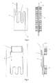
- a heat transfer device combined a flatten loop heat pipe and a vapor camber, comprises an evaporator (1), a compensation chamber (2) and a vapor chamber(3); both the evaporator (1) and the compensation chamber (2) are in the same container (7); the cold side (11) of the evaporator (1) is connect to the compensation chamber(2), and the hot side(12) of the evaporator (1) is connect to the condensing side (35) of the vapor chamber(3); the wick (4) is installed in the evaporator (1); the bottom of the wick (4) and the evaporator (1) form the vapor grooves (41); the vapor grooves (41) is connected to the transport pipe(5), and condenser locates on the outside surface of the transport pipe (5), the returning part of the transport pipe (5) is connected to the compensation chamber (2); the metal mesh (31) is attached on the inside surface of the vapor chamber (3); the metal mesh coats a metal plate (32) with vent holes, and with supports on the both sides(34);
- the outside surface of the container (7) has the temperature control fins (8).
- the bottom of the wick (4) has both horizontal and vertical grooves.
- the metal mesh (31) is larger than 100mesh.
- the condenser (6) comprises condensing clip ring (61) and condensing fins (62), and the condensing fins (62) locate on the outside surface of the condensing clip rings (61), as shown in Fig.2 .
- the evaporation part (36) of the vapor chamber (3) is attached on the heat load Q (chips), and the working fluid inside the vapor chamber (3) will evaporate, then the saturated vapor will go through the vent holes in the metal plate(32) and transfer the heat to the condense part (35) to condense into the liquid, which will attached on the metal mesh (31), and then flows back to the bottom of the evaporation part (36) of the vapor chamber (3) driven by the capillary force from the metal mesh (31).
- the evaporator (1) For the evaporator (1), its evaporation part (12) is connect with the condensation part (35) of the vapor chamber (3), and the wick (44) is inside the evaporator (1).
- the evaporator (1) When the evaporator (1) is heated by the vapor chamber (3), the liquid in the wick (4) will evaporate, and the vapor flows through the grooves (41) to the transfer pipe (5), then condense in the condenser (6) to become the liquid again, and finally back to the compensation chamber (2) and the wick (4).
- Fig.3 is the structural sketch of the clip plate condenser.
- the condenser (6) comprises a condensing clip plate (63) and condensing fins (62), and the condensing fins (62) locate on the outside surface of the condensing clip plate (63) which can be one-side or double-side clip plate.
- Fig.4 is the structural sketch of such a heat transfer device with both the condensing fins and the temperature control fins.
- the condensing clip plate (63) is extended to the whole device, and both the temperature control fins (8) and the condensing fins (62) locate on the other side of the condensing clip plate (63).
Landscapes
- Engineering & Computer Science (AREA)
- Physics & Mathematics (AREA)
- Thermal Sciences (AREA)
- Mechanical Engineering (AREA)
- General Engineering & Computer Science (AREA)
- Life Sciences & Earth Sciences (AREA)
- Sustainable Development (AREA)
- Cooling Or The Like Of Electrical Apparatus (AREA)
- Cooling Or The Like Of Semiconductors Or Solid State Devices (AREA)
Applications Claiming Priority (2)
| Application Number | Priority Date | Filing Date | Title |
|---|---|---|---|
| CNB2007100280445A CN100460798C (zh) | 2007-05-16 | 2007-05-16 | 一种均温回路热管装置 |
| PCT/CN2008/000898 WO2008138216A1 (fr) | 2007-05-16 | 2008-05-05 | Dispositif caloduc en boucle a temperature uniforme |
Publications (1)
| Publication Number | Publication Date |
|---|---|
| EP2154461A1 true EP2154461A1 (fr) | 2010-02-17 |
Family
ID=38865550
Family Applications (1)
| Application Number | Title | Priority Date | Filing Date |
|---|---|---|---|
| EP08748456A Withdrawn EP2154461A1 (fr) | 2007-05-16 | 2008-05-05 | Dispositif caloduc en boucle a temperature uniforme |
Country Status (7)
| Country | Link |
|---|---|
| US (1) | US20100300656A1 (fr) |
| EP (1) | EP2154461A1 (fr) |
| JP (1) | JP2010527432A (fr) |
| CN (1) | CN100460798C (fr) |
| AU (1) | AU2008250879B2 (fr) |
| CA (1) | CA2687005C (fr) |
| WO (1) | WO2008138216A1 (fr) |
Families Citing this family (53)
| Publication number | Priority date | Publication date | Assignee | Title |
|---|---|---|---|---|
| CN100460798C (zh) * | 2007-05-16 | 2009-02-11 | 中山大学 | 一种均温回路热管装置 |
| US9163883B2 (en) | 2009-03-06 | 2015-10-20 | Kevlin Thermal Technologies, Inc. | Flexible thermal ground plane and manufacturing the same |
| JP5112374B2 (ja) * | 2009-04-09 | 2013-01-09 | 北京奇宏科技研發中心有限公司 | 電子機器用放熱装置及びその製造方法 |
| CN101581547B (zh) * | 2009-06-09 | 2011-05-25 | 中山大学 | 一种环路热管散热器 |
| CN101929816B (zh) * | 2009-06-24 | 2012-06-27 | 扬光绿能股份有限公司 | 回路式热管及其制作方法 |
| CN102042776A (zh) | 2009-10-16 | 2011-05-04 | 富准精密工业(深圳)有限公司 | 回路热管 |
| JP5626353B2 (ja) * | 2010-10-08 | 2014-11-19 | 富士通株式会社 | 半導体パッケージ、冷却機構、及び半導体パッケージの製造方法 |
| WO2012059975A1 (fr) * | 2010-11-01 | 2012-05-10 | 富士通株式会社 | Tuyau de chaleur en forme de boucle et dispositif électronique équipé de celui-ci |
| CN102760709B (zh) * | 2011-04-29 | 2015-05-13 | 北京奇宏科技研发中心有限公司 | 环路热管结构 |
| FR2979981B1 (fr) * | 2011-09-14 | 2016-09-09 | Euro Heat Pipes | Dispositif de transport de chaleur a pompage capillaire |
| RU2474780C1 (ru) * | 2011-10-18 | 2013-02-10 | Федеральное государственное унитарное предприятие "Научно-производственное объединение им. С.А. Лавочкина" | Терморегулирующее устройство на базе контурной тепловой трубы |
| KR20130064936A (ko) * | 2011-12-09 | 2013-06-19 | 현대자동차주식회사 | 차량용 열교환기 |
| US20130206369A1 (en) * | 2012-02-13 | 2013-08-15 | Wei-I Lin | Heat dissipating device |
| US9599408B1 (en) * | 2012-03-03 | 2017-03-21 | Advanced Cooling Technologies, Inc. | Loop heat pipe evaporator including a second heat pipe |
| CN103256841B (zh) * | 2013-04-25 | 2016-05-11 | 上海卫星工程研究所 | 一种储能散热装置 |
| JP6123555B2 (ja) * | 2013-08-06 | 2017-05-10 | 富士通株式会社 | 二相流冷却装置及び二相流冷却装置用蒸発器 |
| US12523431B2 (en) * | 2014-09-15 | 2026-01-13 | Kelvin Thermal Technologies, Inc. | Polymer-based microfabricated thermal ground plane |
| US9921004B2 (en) | 2014-09-15 | 2018-03-20 | Kelvin Thermal Technologies, Inc. | Polymer-based microfabricated thermal ground plane |
| CN106794562B (zh) | 2014-09-17 | 2019-07-23 | 科罗拉多州立大学董事会法人团体 | 启用微柱的热接地平面 |
| US11988453B2 (en) | 2014-09-17 | 2024-05-21 | Kelvin Thermal Technologies, Inc. | Thermal management planes |
| US12385697B2 (en) | 2014-09-17 | 2025-08-12 | Kelvin Thermal Technologies, Inc. | Micropillar-enabled thermal ground plane |
| US11598594B2 (en) | 2014-09-17 | 2023-03-07 | The Regents Of The University Of Colorado | Micropillar-enabled thermal ground plane |
| CN104613802B (zh) * | 2015-03-03 | 2017-11-21 | 湖南中科热控技术有限公司 | 一种环路热管的蒸发器和散热装置 |
| CN104776611B (zh) * | 2015-04-11 | 2017-10-27 | 郑州大学 | 内置通道集热蒸发器及具有该集热蒸发器的太阳能热水器 |
| CN104776622B (zh) * | 2015-04-11 | 2017-10-27 | 郑州大学 | 外置通道集热蒸发器及具有该集热蒸发器的太阳能热水器 |
| CN104879933B (zh) * | 2015-04-11 | 2017-10-27 | 郑州大学 | 蒸汽箱集热蒸发器及具有该集热蒸发器的太阳能热水器 |
| CN107278089B (zh) * | 2016-04-07 | 2019-07-19 | 讯凯国际股份有限公司 | 热导结构 |
| US12104856B2 (en) | 2016-10-19 | 2024-10-01 | Kelvin Thermal Technologies, Inc. | Method and device for optimization of vapor transport in a thermal ground plane using void space in mobile systems |
| US10724804B2 (en) | 2016-11-08 | 2020-07-28 | Kelvin Thermal Technologies, Inc. | Method and device for spreading high heat fluxes in thermal ground planes |
| US20180209745A1 (en) * | 2017-01-26 | 2018-07-26 | Asia Vital Components Co., Ltd. | Loop heat pipe structure |
| CN114577046B (zh) | 2017-05-08 | 2024-08-27 | 开文热工科技公司 | 热管理平面 |
| US10842044B2 (en) * | 2017-07-10 | 2020-11-17 | Rolls-Royce North American Technologies, Inc. | Cooling system in hybrid electric propulsion gas turbine engine |
| US10934936B2 (en) | 2017-07-10 | 2021-03-02 | Rolls-Royce North American Technologies, Inc. | Cooling system in a hybrid electric propulsion gas turbine engine for cooling electrical components therein |
| US10354356B2 (en) * | 2017-11-02 | 2019-07-16 | Dell Products L.P. | Systems and methods for interconnecting and cooling multiple graphics processing unit (GPU) cards |
| CN108119232B (zh) * | 2017-12-11 | 2024-03-12 | 东南大学 | 一种具有均温装置的极地发电舱 |
| US10820454B2 (en) | 2018-01-31 | 2020-10-27 | Toyota Motor Engineering & Manufacturing North America, Inc. | Vapor chamber heat spreaders with engineered vapor and liquid flow paths |
| CN108278917B (zh) * | 2018-03-12 | 2024-03-26 | 上海利正卫星应用技术有限公司 | 平板式蒸发器及平板式环路热管 |
| CN108770283A (zh) * | 2018-05-04 | 2018-11-06 | 北京空间飞行器总体设计部 | 基于小尺寸冷凝器的大功率风冷环路热管散热器 |
| US10968830B2 (en) | 2018-06-22 | 2021-04-06 | Rolls-Royce North American Technologies, Inc. | Systems and methods for cooling electronics and electrical machinery in a hybrid electric aircraft |
| JP6904321B2 (ja) * | 2018-10-25 | 2021-07-14 | セイコーエプソン株式会社 | 冷却装置及びプロジェクター |
| US12498181B2 (en) | 2018-12-11 | 2025-12-16 | Kelvin Thermal Technologies, Inc. | Vapor chamber |
| JP2020101345A (ja) * | 2018-12-25 | 2020-07-02 | 株式会社フジクラ | 車載バッテリ冷却構造 |
| US20200236806A1 (en) * | 2019-01-18 | 2020-07-23 | United Arab Emirates University | Heat sink with internal chamber for phase change material |
| JP2020148410A (ja) * | 2019-03-14 | 2020-09-17 | セイコーエプソン株式会社 | 冷却装置およびプロジェクター |
| CN110848820A (zh) * | 2019-10-22 | 2020-02-28 | 青岛海尔空调器有限总公司 | 散热器和空调器 |
| WO2021258028A1 (fr) | 2020-06-19 | 2021-12-23 | Kelvin Thermal Technologies, Inc. | Plan de masse thermique pliable |
| RU2757740C1 (ru) * | 2021-03-19 | 2021-10-21 | Акционерное общество "Научно-производственное объединение им. С.А. Лавочкина" (АО "НПО Лавочкина") | Регулируемая контурная тепловая труба |
| CN115790222B (zh) * | 2021-09-09 | 2026-01-06 | 珠海德标光电科技有限公司 | 一种柔性热管的制备方法以及一种柔性热管 |
| US20230247799A1 (en) * | 2022-02-01 | 2023-08-03 | Cisco Technology, Inc. | Heat pipe with localized heatsink |
| CN117091436A (zh) * | 2022-05-11 | 2023-11-21 | 智惠创富股份有限公司 | 均温板与热管竖立接合的毛细连通结构 |
| CN116906676A (zh) * | 2023-06-25 | 2023-10-20 | 华能国际电力江苏能源开发有限公司 | 一种热量回收蒸汽管道吊装架 |
| CN119958336A (zh) * | 2023-11-07 | 2025-05-09 | 北京小米移动软件有限公司 | 环路热管、壳体部件以及电子设备 |
| US12576693B2 (en) * | 2024-01-12 | 2026-03-17 | Toyota Motor Engineering & Manufacturing North America, Inc. | Cooling systems and assemblies, and vehicles including the same |
Family Cites Families (15)
| Publication number | Priority date | Publication date | Assignee | Title |
|---|---|---|---|---|
| DE2120477C3 (de) * | 1971-04-27 | 1980-07-31 | Brown, Boveri & Cie Ag, 6800 Mannheim | Elektrisch isolierende Wärmerohranordnung für hohe Wärmestromdichte |
| US4588023A (en) * | 1980-06-16 | 1986-05-13 | Showa Aluminum Corporation | Device for releasing heat |
| JPS62272091A (ja) * | 1986-05-21 | 1987-11-26 | Hitachi Cable Ltd | ヒ−トパイプ |
| JPH0424490A (ja) * | 1990-05-17 | 1992-01-28 | Ishikawajima Harima Heavy Ind Co Ltd | キャピラリーポンプ |
| JP3164518B2 (ja) * | 1995-12-21 | 2001-05-08 | 古河電気工業株式会社 | 平面型ヒートパイプ |
| JP2000161878A (ja) * | 1998-11-30 | 2000-06-16 | Furukawa Electric Co Ltd:The | 平面型ヒートパイプ |
| JP4676090B2 (ja) * | 2001-06-08 | 2011-04-27 | 古河電気工業株式会社 | 板型ヒートパイプ |
| US7473995B2 (en) * | 2002-03-25 | 2009-01-06 | Intel Corporation | Integrated heat spreader, heat sink or heat pipe with pre-attached phase change thermal interface material and method of making an electronic assembly |
| US20040011509A1 (en) * | 2002-05-15 | 2004-01-22 | Wing Ming Siu | Vapor augmented heatsink with multi-wick structure |
| JP2005257251A (ja) * | 2004-03-12 | 2005-09-22 | Ts Heatronics Co Ltd | 放熱器 |
| CN2739690Y (zh) * | 2004-11-12 | 2005-11-09 | 珍通科技股份有限公司 | 均温板 |
| CN1784137A (zh) * | 2004-11-29 | 2006-06-07 | 迈萪科技股份有限公司 | 具有金属网微结构的可绕曲式均热板及其制法 |
| CN100370890C (zh) * | 2005-06-27 | 2008-02-20 | 中山大学 | 一种平板式回路热管装置 |
| CN201053838Y (zh) * | 2007-05-16 | 2008-04-30 | 中山大学 | 一种均温回路热管装置 |
| CN100460798C (zh) * | 2007-05-16 | 2009-02-11 | 中山大学 | 一种均温回路热管装置 |
-
2007
- 2007-05-16 CN CNB2007100280445A patent/CN100460798C/zh not_active Expired - Fee Related
-
2008
- 2008-05-05 US US12/599,786 patent/US20100300656A1/en not_active Abandoned
- 2008-05-05 EP EP08748456A patent/EP2154461A1/fr not_active Withdrawn
- 2008-05-05 JP JP2010507779A patent/JP2010527432A/ja active Pending
- 2008-05-05 WO PCT/CN2008/000898 patent/WO2008138216A1/fr not_active Ceased
- 2008-05-05 CA CA2687005A patent/CA2687005C/fr not_active Expired - Fee Related
- 2008-05-05 AU AU2008250879A patent/AU2008250879B2/en not_active Ceased
Non-Patent Citations (1)
| Title |
|---|
| See references of WO2008138216A1 * |
Also Published As
| Publication number | Publication date |
|---|---|
| CA2687005C (fr) | 2013-11-19 |
| AU2008250879B2 (en) | 2010-03-04 |
| CA2687005A1 (fr) | 2008-11-20 |
| US20100300656A1 (en) | 2010-12-02 |
| AU2008250879A1 (en) | 2008-11-20 |
| CN100460798C (zh) | 2009-02-11 |
| WO2008138216A1 (fr) | 2008-11-20 |
| CN101059321A (zh) | 2007-10-24 |
| JP2010527432A (ja) | 2010-08-12 |
Similar Documents
| Publication | Publication Date | Title |
|---|---|---|
| EP2154461A1 (fr) | Dispositif caloduc en boucle a temperature uniforme | |
| US20190154353A1 (en) | Heat pipe having a wick with a hybrid profile | |
| CN107131784B (zh) | 基于平板环路热管的均热板 | |
| TW200643362A (en) | Loop-type heat exchange apparatus | |
| WO2008095404A1 (fr) | Dispositif à tuyaux de chaleur en boucle avec multicanal autorégulé | |
| CN108444320B (zh) | 一种蒸汽管道宽度大于液体管道宽度的平板式微型环路热管 | |
| CN108362148A (zh) | 组合式冷板 | |
| CN100334931C (zh) | 用于cpl的带散热片的平面式毛细芯蒸发器 | |
| CN108709443B (zh) | 一种微通道平板环路热管 | |
| CN102261862A (zh) | 一种平板热管换热器 | |
| CN100366997C (zh) | 具有平面式蒸发器和冷凝器的毛细抽吸两相流体回路 | |
| CN100366998C (zh) | 一种用于毛细抽吸两相流体回路的平面式毛细芯冷凝器 | |
| CN100334930C (zh) | 一种用于cpl的平面式毛细芯蒸发器 | |
| CN101581547B (zh) | 一种环路热管散热器 | |
| CN105371676A (zh) | 一种双毛细芯蒸发器 | |
| CN107094360B (zh) | 一种平板式微型环路热管系统 | |
| CN201053838Y (zh) | 一种均温回路热管装置 | |
| CN116518760B (zh) | 一种分流通道式平板环路热管 | |
| CN107087375B (zh) | 一种蒸发室和蒸汽管道不直接连通的平板式环路热管 | |
| KR20190081999A (ko) | 루프형 히트 파이프 | |
| CN205718603U (zh) | 蒸发器与冷凝器角度可调的环路热管 | |
| CN205105508U (zh) | 一种热管散热装置 | |
| KR200448243Y1 (ko) | 열 확산장치 | |
| TW200702611A (en) | Loop-type heat exchange device | |
| TW200720557A (en) | Two-phase closed-loop thermosyphon cooling device |
Legal Events
| Date | Code | Title | Description |
|---|---|---|---|
| PUAI | Public reference made under article 153(3) epc to a published international application that has entered the european phase |
Free format text: ORIGINAL CODE: 0009012 |
|
| 17P | Request for examination filed |
Effective date: 20091214 |
|
| AK | Designated contracting states |
Kind code of ref document: A1 Designated state(s): AT BE BG CH CY CZ DE DK EE ES FI FR GB GR HR HU IE IS IT LI LT LU LV MC MT NL NO PL PT RO SE SI SK TR |
|
| AX | Request for extension of the european patent |
Extension state: AL BA MK RS |
|
| RIN1 | Information on inventor provided before grant (corrected) |
Inventor name: CHIN, CHI-TE Inventor name: LU, SHU-SHEN |
|
| DAX | Request for extension of the european patent (deleted) | ||
| STAA | Information on the status of an ep patent application or granted ep patent |
Free format text: STATUS: THE APPLICATION IS DEEMED TO BE WITHDRAWN |
|
| 18D | Application deemed to be withdrawn |
Effective date: 20121201 |