EP2154477A2 - Segmentierter Optikschaltungsantrieb für Glasfasersensoren mit geschlossener Schlaufe - Google Patents
Segmentierter Optikschaltungsantrieb für Glasfasersensoren mit geschlossener Schlaufe Download PDFInfo
- Publication number
- EP2154477A2 EP2154477A2 EP09167101A EP09167101A EP2154477A2 EP 2154477 A2 EP2154477 A2 EP 2154477A2 EP 09167101 A EP09167101 A EP 09167101A EP 09167101 A EP09167101 A EP 09167101A EP 2154477 A2 EP2154477 A2 EP 2154477A2
- Authority
- EP
- European Patent Office
- Prior art keywords
- analog
- digital
- data
- circuit
- measurement data
- Prior art date
- Legal status (The legal status is an assumption and is not a legal conclusion. Google has not performed a legal analysis and makes no representation as to the accuracy of the status listed.)
- Withdrawn
Links
Images



Classifications
-
- G—PHYSICS
- G01—MEASURING; TESTING
- G01C—MEASURING DISTANCES, LEVELS OR BEARINGS; SURVEYING; NAVIGATION; GYROSCOPIC INSTRUMENTS; PHOTOGRAMMETRY OR VIDEOGRAMMETRY
- G01C19/00—Gyroscopes; Turn-sensitive devices using vibrating masses; Turn-sensitive devices without moving masses; Measuring angular rate using gyroscopic effects
- G01C19/58—Turn-sensitive devices without moving masses
- G01C19/64—Gyrometers using the Sagnac effect, i.e. rotation-induced shifts between counter-rotating electromagnetic beams
- G01C19/72—Gyrometers using the Sagnac effect, i.e. rotation-induced shifts between counter-rotating electromagnetic beams with counter-rotating light beams in a passive ring, e.g. fibre laser gyrometers
- G01C19/726—Phase nulling gyrometers, i.e. compensating the Sagnac phase shift in a closed loop system
-
- H—ELECTRICITY
- H03—ELECTRONIC CIRCUITRY
- H03M—CODING; DECODING; CODE CONVERSION IN GENERAL
- H03M1/00—Analogue/digital conversion; Digital/analogue conversion
- H03M1/66—Digital/analogue converters
- H03M1/68—Digital/analogue converters with conversions of different sensitivity, i.e. one conversion relating to the more significant digital bits and another conversion to the less significant bits
Definitions
- the present invention generally relates to gyro systems, and more particularly to modulating optical signals in interferometric fiber optic gyros (IFOGs).
- IFOGs interferometric fiber optic gyros
- a basic conventional fiber optic gyro includes a light source, a beam generating device, and a coil of optical fiber coupled to the beam generating device that encircles an area about a sensing axis.
- the beam generating device transmits light beams into the coil that propagate in a clockwise (CW) direction and a counter-clockwise (CCW) direction along the core of the optical fiber and both ultimately impinge on a photodetector (e.g., a photodiode electrically coupled to a photodetection system).
- CW clockwise
- CCW counter-clockwise
- Many FOGs utilize glass-based optical fibers that conduct light along a solid glass core of the fiber.
- the two counter-propagating (e.g., CW and CCW) beams experience different optical path lengths while propagating around a rotating closed optical path or loop.
- rotation about the sensing axis increases the optical path length in one rotational direction and decreases the optical path length in the other rotation direction.
- the difference in the two optical path lengths introduces a phase shift between the light beams for either rotation direction (i.e., the Sagnac effect), and this difference is proportional to the rotational rate that is normal to the enclosed area.
- the phase difference between the counter-propagating light beams in the loop is typically modulated to increase sensitivity to rotation detection using an optical phase modulator coupled with a bias signal generator.
- the optical phase modulator may be operated in a feedback loop from the photodetection system to provide sufficient negative feedback for canceling the phase shift difference, between the counter-propagating light beams, resulting from a rotation about the sensing axis.
- a phase-sensitive detector receives a signal representing the photodetector output current and provides an indication of the relative phase of the light beams impinging on the photodetector. Any significant signal content recovered by the phase-sensitive detector at the modulation frequency is proportional to the rotation rate.
- the signal from the phase-sensitive detector may be used to phase shift one light beam relative to the other beam to bring the counter-propagating beams in phase with each other.
- the signal from the phase-sensitive detector may be supplied to servo electronics having an accumulator, such as an integrator. In response to the phase differences generated during rotation, the servo electronics supplies a signal to phase shift one light beam relative to the other beam.
- an analog-to-digital converter converts the analog output of the photodetector to a digital equivalent (e.g., for use by the phase-sensitive detector)
- DAC digital-to-analog converter
- the gyroscope is generally less sensitive to phase detection. This region is referred to as a "deadband," and deadband errors may occur for a number of reasons.
- One source of deadband results from the truncation of digital signals from the servo electronics to lower bit values prior to supplying the digital signal to the DAC. This truncation can also introduce an asymmetry that, in the presence of vibration, could rectify into rate error. Additionally, loop error may take a significant amount of time to converge to the appropriate phase shift, and this time for convergence may be further extended with the truncation of signals supplied to the DAC.
- Closed-loop optical sensors such as the fiber optic gyros discussed above, typically contain an Integrated Optics Circuit (IOC) modulation component that is driven with a 12 to 16 bit truncated signal received from a single high resolution Digital to Analog Converter (DAC).
- IOC Integrated Optics Circuit
- DAC Digital to Analog Converter
- the resolution metrics of these sensors are substantially limited by the data truncation associated with the use of only one high resolution DAC in the IOC drive component of the sensors.
- these truncated signals can cause undesirable deadband errors.
- the least significant bit of a 12-bit resolution DAC scales to a several hundreds of degrees per hour bias error. Even though over a long period of time the closed-loop architecture maintains a bias error which averages to zero, quantization error remains in terms of angle white noise.
- One solution utilized to improve bit resolution in closed loop fiber optic gyros is to employ a higher resolution DAC in the IOC drive. Unfortunately, these high resolution converters are expensive and still require truncation well below 23-bit resolution.
- Another solution utilized to reduce truncation error associated with the use of a single DAC in the IOC drive circuit of fiber optic gyros is to implement a technique that introduces noise and averaging to the signal processing or drive components. Unfortunately, such techniques invariably inject certain unwanted noise into the converter component. This unwanted noise can lead to inconsistent sensor output and decreased system throughput.
- An example optical sensor system includes an optics circuit that generates analog measurement data, a detector circuit that detects the analog measurement data and then converts the analog measurement data to a digital measurement data, a signal processing circuit that demodulates the digital measurement data and then generates a segmented digital signal based on the demodulated digital measurement data, and an optics drive circuit that generates an analog drive signal based on the segmented digital signal, wherein the analog drive signal is used to drive the optical circuit.
- the optics drive component includes a first converter that converts a first digital data segment of the segmented digital signal to a first analog data segment and a second converter that converts a second digital data segment of the segmented digital signal to a second analog data segment.
- the first digital data segment corresponds to more significant bits of data than the second digital data segment.
- the optical drive circuit is further amplifies the first and second analog data segments and then combines the amplified analog data segments into a single analog drive signal.
- the generated analog drive signal of the optical drive circuit has greater resolution than the first converter.
- the generated digital measurement data and the analog drive signal correspond to data with at least 16-bit resolution.
- the invention provides means for improving the output resolution of an optical drive component in an optical sensor.
- FIGURE 1 illustrates a block diagram of a closed loop fiber optic gyro formed in accordance with an embodiment of the present invention
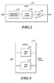
- FIGURE 2 illustrates a block diagram of an IOC drive component formed in accordance with an embodiment of the present invention
- FIGURE 3 illustrates a block diagram of a segmented DAC component in an IOC drive formed in accordance with an embodiment of the present invention
- FIGURE 4 illustrates a gain circuit in an IOC drive formed in accordance with an embodiment of the present invention.
- FIGURE 5 illustrates a flow diagram of a process associated with an IOC drive formed in accordance with an embodiment of the present invention.
- the present invention relates to a system and method for improving the output resolution of an optical drive circuit in an optical sensor device.
- the output bit resolution of an optical drive circuit can be significantly increased by segmenting data conversion between two distinct converter components in the optical drive circuit.
- FIGURE 1 illustrates a closed-loop architecture of an optical sensor 8 formed in accordance with an embodiment of the present invention.
- the closed-loop sensor 8 includes an integrated optics circuit (IOC) 10, a photodetection circuit (PDC) 20, a signal processing circuit (SPC) 30, and an optics drive circuit (ODC) 40.
- IOC integrated optics circuit
- PDC photodetection circuit
- SPC signal processing circuit
- ODC optics drive circuit
- the closed loop optical sensor 8 may be one of any number of different types of closed-loop sensors, for example, closed-loop fiber optic sensors and gyros.
- the optical sensor 8 When the optical sensor 8 is implemented as a closed-loop fiber optic gyro, the sensor 8 measures an angular velocity or a velocity about a particular axis of rotation by determining a difference in phase between two beams of light travelling in opposite directions (e.g., clockwise and counterclockwise directions) around the fiber optic coils of the IOC 10.
- the analog optical output of the IOC 10 is communicated to the PDC 20, wherein the analog optical output is amplified and converted to digital phase shift data.
- the digital phase shift data of the PDC 20 is then communicated to the SPC 30 of the gyro, where it is demodulated, detected, and communicated to the ODC 40.
- the ODC 40 then converts the demodulated digital phase shift data to analog form, amplifies the analog data, and then communicates the amplified analog data to the IOC 10 through a feedback loop.
- the bit resolution measured by a fiber optic gyro can be as high as 23 bits, prior to data conversion and subsequent signal processing.
- traditional nonsegmented IOC drives measure a phase shift at a 23 bit resolution and then degrade this resolution to below 16 bits during a truncation processing step, which occurs in the SPC 30.
- bit data is truncated before being communicated to a single high resolution DAC in the ODC 40. This truncation can cause an error with a magnitude as high as one half of the least significant bit (LSB) of data.
- LSB least significant bit
- the SPC 30 of the present invention does not require such a truncation processing step and removes the one half LSB data error associated with traditional nonsegmented IOC drives.
- the SPC 30 of the present invention segments 23 bit data into a Most Significant Bit (MSB) data portion (typically ranging between 10 to 14 bits in length) and a LSB data portion (comprising the remaining bit resolution) for processing at parallel Digital to Analog Converters (DAC) in the ODC 40.
- MSB/LSB data segmentation occurs at the ODC 40 instead of at the SPC 30.
- the parallel DACs of the ODC 40 then convert the 23 bits of segmented MSB/LSB data to analog signal data and then amplify and combine this high precision signal data to drive the IOC 10.
- the combination of analog signal data occurs before the amplification step.
- FIGURE 2 illustrates the ODC 40 formed in accordance with an embodiment of the present invention.
- the ODC 40 includes a segmented video DAC (SVDAC) 42, a gain circuit 46, and an amplifier component 48.
- the SVDAC 42 receives data representing a 23 bit digital signal from the SPC 30. This signal is segmented into a MSB component and a LSB component and then converted to an analog signal by the SVDAC 42. After conversion processing, a gain is applied to the analog MSB and LSB signal components utilizing the gain circuit 46. After gain processing the analog signals are combined by the amplifier 48 and output the IOC 10. In accordance with an alternate embodiment of the present invention, gain is applied after the analog signals are combined by the amplifier 48, prior to outputting the analog signal to the IOC 10. In accordance with another embodiment the gain processing could comprise either electrical or optical gain processing.
- the contents of the SVDAC 42 are illustrated in FIGURE 3 .
- the SVDAC 42 includes a MSB DAC 43 and a LSB DAC 45.
- the MSB DAC 43 receives and converts the most significant bits of data segmented from a 23 bit data signal and the LSB DAC 45 receives and converts the least significant bits of data segmented from the same 23 bit signal.
- the MSB/LSB data segmentation occurs at the SPC 30, and in accordance with an alternate embodiment the data segmentation occurs within the ODC 40.
- the segmented analog signals are output to the gain circuit 46, illustratively depicted in FIGURE 4 .
- the segmented analog signals are output to the amplifier 48.
- FIGURE 4 illustrates a gain circuit 46 in accordance with an embodiment of the present invention.
- the gain circuit includes an MSB passive portion including passive circuit elements R1, R2, R5, R6 and R9 and an LSB passive portion including passive circuit elements R3, R4, R7, R8 and R9.
- Both the MSB and LSB signals are output from the gain circuit 46 to the amplifier 48, where they are combined into one high precision analog signal (of 23 bit precision).
- FIGURE 5 illustrates a flow diagram of a process performed by the ODC 40, in accordance with an embodiment of the present invention.
- the process begins at a block 50 after a 23 bit digital data signal is processed by the SPC 30 and segmented into a MSB and a LSB portion.
- the ODC 40 receives the segmented bit signal data from the SPC 30.
- the SVDAC 42 assigns the MSB data to the MSB DAC 43 and the LSB data to the LSB DAC 45, for conversion processing at a block 56.
- the MSB DAC 43 and the LSB DAC 45 independently convert the segmented digital signals to analog signals.
- a gain processing is performed at the gain circuit 46, which facilitates a large gain of the MSB analog data and a smaller gain of the LSB analog data.
- the MSB and LSB analog data are combined into a high precision analog signal which is used to drive the IOC 10.
- the drive processing ends.
Landscapes
- Engineering & Computer Science (AREA)
- Physics & Mathematics (AREA)
- Power Engineering (AREA)
- Optics & Photonics (AREA)
- Electromagnetism (AREA)
- General Physics & Mathematics (AREA)
- Radar, Positioning & Navigation (AREA)
- Remote Sensing (AREA)
- Gyroscopes (AREA)
- Microscoopes, Condenser (AREA)
Applications Claiming Priority (1)
| Application Number | Priority Date | Filing Date | Title |
|---|---|---|---|
| US12/185,428 US7847715B2 (en) | 2008-08-04 | 2008-08-04 | Segmented optics circuit drive for closed loop fiber optic sensors |
Publications (2)
| Publication Number | Publication Date |
|---|---|
| EP2154477A2 true EP2154477A2 (de) | 2010-02-17 |
| EP2154477A3 EP2154477A3 (de) | 2015-02-25 |
Family
ID=41382016
Family Applications (1)
| Application Number | Title | Priority Date | Filing Date |
|---|---|---|---|
| EP09167101.6A Withdrawn EP2154477A3 (de) | 2008-08-04 | 2009-08-03 | Segmentierter Optikschaltungsantrieb für Glasfasersensoren mit geschlossener Schlaufe |
Country Status (3)
| Country | Link |
|---|---|
| US (1) | US7847715B2 (de) |
| EP (1) | EP2154477A3 (de) |
| JP (1) | JP2010038917A (de) |
Cited By (1)
| Publication number | Priority date | Publication date | Assignee | Title |
|---|---|---|---|---|
| EP2515077A3 (de) * | 2011-04-21 | 2016-04-13 | Northrop Grumman LITEF GmbH | Unterdrückung von Quantisierungsrauschen beim faseroptischen Sagnac-Interferometer |
Families Citing this family (9)
| Publication number | Priority date | Publication date | Assignee | Title |
|---|---|---|---|---|
| US10069619B1 (en) | 2011-08-05 | 2018-09-04 | Rockwell Collins, Inc. | Optical sample and hold system and method |
| US9197471B1 (en) | 2011-08-05 | 2015-11-24 | Rockwell Collins, Inc. | Optically interleaved photonic analog to digital converters |
| US8837956B1 (en) | 2012-06-28 | 2014-09-16 | Rockwell Collins, Inc. | Pipelined receiver system and method |
| US8779955B1 (en) * | 2012-09-25 | 2014-07-15 | Rockwell Collins, Inc. | Optical analog-to-digital conversion system and method with enhanced quantization |
| US9140551B2 (en) * | 2013-07-16 | 2015-09-22 | Honeywell International Inc. | Fiber optic gyroscope dead band error suppression |
| US9118423B1 (en) | 2013-08-09 | 2015-08-25 | Rockwell Collins.com | Optical conversion system and method with multiple amplitude processing |
| US9356704B1 (en) | 2013-08-09 | 2016-05-31 | Rockwell Collins, Inc. | Optical conversion system and method with multiple phase processing |
| JP6331356B2 (ja) * | 2013-11-25 | 2018-05-30 | セイコーエプソン株式会社 | 検出装置、センサー、電子機器及び移動体 |
| CN116147603B (zh) * | 2023-01-05 | 2026-03-27 | 陕西华燕航空仪表有限公司 | 光电分离式纯模拟输出微型光纤陀螺及其信号处理方法 |
Family Cites Families (21)
| Publication number | Priority date | Publication date | Assignee | Title |
|---|---|---|---|---|
| EP0013799B1 (de) * | 1978-12-19 | 1985-10-02 | Kabushiki Kaisha Toshiba | Kodierer für Längen- oder Winkelmessvorrichtungen mit hoher Genauigkeit |
| JPS58152355A (ja) * | 1982-03-05 | 1983-09-09 | Jeol Ltd | レンズ電流設定回路 |
| US4544911A (en) * | 1983-08-31 | 1985-10-01 | Rca Corporation | Low cost monotonic digital-to-analog converter |
| US4595910A (en) * | 1983-07-28 | 1986-06-17 | Rca Corporation | Digital-to-analog converter useful in a television receiver |
| DE3706664A1 (de) * | 1987-02-28 | 1988-09-08 | Henkel Kgaa | Fluessige textilbehandlungsmittel |
| US4998108A (en) * | 1990-07-30 | 1991-03-05 | International Business Machines Corporation | Large range, high speed, high accuracy digital-to-analog converter |
| JPH0523031U (ja) * | 1991-09-10 | 1993-03-26 | 株式会社ニコン | 光フアイバジヤイロ装置 |
| EP0551537B1 (de) * | 1992-01-13 | 1995-03-22 | LITEF GmbH | Verfahren und Einrichtung zur Drehratenmessung mittels eines faseroptischen Sagnac-Interferometers |
| JP3245796B2 (ja) * | 1992-10-21 | 2002-01-15 | 株式会社トキメック | 光ファイバジャイロ |
| US5764172A (en) * | 1996-04-05 | 1998-06-09 | Trimble Navigation Limited | Hybrid DAC suitable for use in a GPS receiver |
| US5999304A (en) * | 1997-08-04 | 1999-12-07 | Honeywell, Inc. | Fiber optic gyroscope with deadband error reduction |
| US6396801B1 (en) * | 1998-03-17 | 2002-05-28 | Trw Inc. | Arbitrary waveform modem |
| US6191721B1 (en) * | 1999-11-05 | 2001-02-20 | Litton Systems, Inc. | Time based digital-to-analog conversion of a precision variable amplitude sine wave |
| US6556153B1 (en) * | 2002-01-09 | 2003-04-29 | Anorad Corporation | System and method for improving encoder resolution |
| US6549155B1 (en) * | 2002-01-30 | 2003-04-15 | Texas Instruments Incorporated | Signal conversion using coarse and fine digital to analog converters |
| US6748141B2 (en) * | 2002-03-28 | 2004-06-08 | Agilent Technologies, Inc. | Method, apparatus and system for aligning an optical fiber end with an optical waveguide |
| US6744519B2 (en) * | 2002-04-30 | 2004-06-01 | Honeywell International Inc. | Methods and apparatus for fiber optic gyroscope dead band error suppression modulation |
| JP2005274145A (ja) * | 2004-03-22 | 2005-10-06 | Agilent Technol Inc | 測定方法、モジュールおよびシステム |
| CA2585016A1 (en) * | 2004-10-22 | 2006-05-04 | Tal Gottesman | A signal-enhancement system for photodetector outputs |
| US7515272B2 (en) * | 2006-03-17 | 2009-04-07 | Honeywell International Inc. | Digital feedback systems and methods for optical gyroscopes |
| US7583384B2 (en) * | 2006-07-27 | 2009-09-01 | Honeywell International, Inc. | High resolution IOC drive and method for driving fiber optic gyroscopes |
-
2008
- 2008-08-04 US US12/185,428 patent/US7847715B2/en active Active
-
2009
- 2009-08-03 JP JP2009180986A patent/JP2010038917A/ja active Pending
- 2009-08-03 EP EP09167101.6A patent/EP2154477A3/de not_active Withdrawn
Cited By (1)
| Publication number | Priority date | Publication date | Assignee | Title |
|---|---|---|---|---|
| EP2515077A3 (de) * | 2011-04-21 | 2016-04-13 | Northrop Grumman LITEF GmbH | Unterdrückung von Quantisierungsrauschen beim faseroptischen Sagnac-Interferometer |
Also Published As
| Publication number | Publication date |
|---|---|
| US20100026535A1 (en) | 2010-02-04 |
| JP2010038917A (ja) | 2010-02-18 |
| US7847715B2 (en) | 2010-12-07 |
| EP2154477A3 (de) | 2015-02-25 |
Similar Documents
| Publication | Publication Date | Title |
|---|---|---|
| US7847715B2 (en) | Segmented optics circuit drive for closed loop fiber optic sensors | |
| JP5026882B2 (ja) | 高解像度iocドライブおよび光ファイバジャイロスコープを駆動する方法 | |
| US6744519B2 (en) | Methods and apparatus for fiber optic gyroscope dead band error suppression modulation | |
| US7715014B2 (en) | Methods and systems for fiber optic gyroscopes vibration error suppression | |
| US8294900B2 (en) | Systems and methods for resonator fiber optic gyroscope intensity modulation control | |
| US8908187B2 (en) | System and method for reducing errors in a resonator fiber optic gyroscope | |
| US8830479B2 (en) | RFOG with optical heterodyning for optical signal discrimination | |
| US5949545A (en) | Fiber optic gyroscope with variable output period | |
| CN106979776B (zh) | 一种基于西格玛德尔塔调制的光纤陀螺的数字闭环控制方法 | |
| US7630082B2 (en) | Systems and methods for high precision feedback control in closed loop sensors | |
| CN112648991B (zh) | 一种闭环光纤陀螺仪的死区克服系统及其方法 | |
| JP2004516695A (ja) | 非線形制御法を用いた閉ループ光ファイバージャイロスコープの自動利得制御 | |
| CN109029412B (zh) | 一种光纤陀螺闭环反馈回路非线性度测试方法及系统 | |
| CN115855015B (zh) | 一种解决光纤陀螺大角冲击的方法 | |
| JPH04130212A (ja) | 回転速度の測定のための光ファイバサニャック干渉計 | |
| EP1208354B1 (de) | Verbesserter faseroptischer kreisel | |
| JPH0816614B2 (ja) | 多重化3軸ジャイロ用ループ制御装置 | |
| Zheng et al. | Wide dynamic range experiments on a resonator fiber optic gyro based on closed-loop frequency locking technique | |
| US8842286B2 (en) | Suppression of quantization noise in a fiber-optic sagnac interferometer | |
| US5999260A (en) | Method and apparatus for initialization of a fiber optic gyroscope | |
| US20010035958A1 (en) | Dual signal modulation scheme for eliminating non-linearity in a system | |
| CN121761856A (zh) | 一种用于实现光纤陀螺精度保持的调制解调系统 | |
| JP2000258168A (ja) | 光干渉角速度計 | |
| JPH04184116A (ja) | 光ファイバジャイロの零オフセット消去方法 | |
| JPH07117418B2 (ja) | 光干渉角速度計 |
Legal Events
| Date | Code | Title | Description |
|---|---|---|---|
| PUAI | Public reference made under article 153(3) epc to a published international application that has entered the european phase |
Free format text: ORIGINAL CODE: 0009012 |
|
| 17P | Request for examination filed |
Effective date: 20090803 |
|
| AK | Designated contracting states |
Kind code of ref document: A2 Designated state(s): AT BE BG CH CY CZ DE DK EE ES FI FR GB GR HR HU IE IS IT LI LT LU LV MC MK MT NL NO PL PT RO SE SI SK SM TR |
|
| AX | Request for extension of the european patent |
Extension state: AL BA RS |
|
| PUAL | Search report despatched |
Free format text: ORIGINAL CODE: 0009013 |
|
| AK | Designated contracting states |
Kind code of ref document: A3 Designated state(s): AT BE BG CH CY CZ DE DK EE ES FI FR GB GR HR HU IE IS IT LI LT LU LV MC MK MT NL NO PL PT RO SE SI SK SM TR |
|
| AX | Request for extension of the european patent |
Extension state: AL BA RS |
|
| RIC1 | Information provided on ipc code assigned before grant |
Ipc: H03M 1/68 20060101ALI20150119BHEP Ipc: G01C 19/72 20060101AFI20150119BHEP |
|
| 17Q | First examination report despatched |
Effective date: 20150227 |
|
| STAA | Information on the status of an ep patent application or granted ep patent |
Free format text: STATUS: THE APPLICATION IS DEEMED TO BE WITHDRAWN |
|
| 18D | Application deemed to be withdrawn |
Effective date: 20150710 |