EP2154493A2 - Capteur de flux 300°C - Google Patents
Capteur de flux 300°C Download PDFInfo
- Publication number
- EP2154493A2 EP2154493A2 EP09008739A EP09008739A EP2154493A2 EP 2154493 A2 EP2154493 A2 EP 2154493A2 EP 09008739 A EP09008739 A EP 09008739A EP 09008739 A EP09008739 A EP 09008739A EP 2154493 A2 EP2154493 A2 EP 2154493A2
- Authority
- EP
- European Patent Office
- Prior art keywords
- measuring device
- exhaust pipe
- carrier
- housing
- sealed
- Prior art date
- Legal status (The legal status is an assumption and is not a legal conclusion. Google has not performed a legal analysis and makes no representation as to the accuracy of the status listed.)
- Withdrawn
Links
Images

Classifications
-
- G—PHYSICS
- G01—MEASURING; TESTING
- G01F—MEASURING VOLUME, VOLUME FLOW, MASS FLOW OR LIQUID LEVEL; METERING BY VOLUME
- G01F1/00—Measuring the volume flow or mass flow of fluid or fluent solid material wherein the fluid passes through a meter in a continuous flow
- G01F1/68—Measuring the volume flow or mass flow of fluid or fluent solid material wherein the fluid passes through a meter in a continuous flow by using thermal effects
- G01F1/684—Structural arrangements; Mounting of elements, e.g. in relation to fluid flow
- G01F1/688—Structural arrangements; Mounting of elements, e.g. in relation to fluid flow using a particular type of heating, cooling or sensing element
- G01F1/69—Structural arrangements; Mounting of elements, e.g. in relation to fluid flow using a particular type of heating, cooling or sensing element of resistive type
- G01F1/692—Thin-film arrangements
-
- F—MECHANICAL ENGINEERING; LIGHTING; HEATING; WEAPONS; BLASTING
- F02—COMBUSTION ENGINES; HOT-GAS OR COMBUSTION-PRODUCT ENGINE PLANTS
- F02M—SUPPLYING COMBUSTION ENGINES IN GENERAL WITH COMBUSTIBLE MIXTURES OR CONSTITUENTS THEREOF
- F02M26/00—Engine-pertinent apparatus for adding exhaust gases to combustion-air, main fuel or fuel-air mixture, e.g. by exhaust gas recirculation [EGR] systems
- F02M26/45—Sensors specially adapted for EGR systems
- F02M26/46—Sensors specially adapted for EGR systems for determining the characteristics of gases, e.g. composition
- F02M26/47—Sensors specially adapted for EGR systems for determining the characteristics of gases, e.g. composition the characteristics being temperatures, pressures or flow rates
Definitions
- the present invention relates to the measurement in exhaust gas streams, in particular anemometric measurements, for the exhaust gas recirculation of internal combustion engines.
- EP 95 911 257 discloses hot film anemometer.
- EP 0 990 674 A discloses an exhaust gas recirculation.
- EP 06 806 497 and WO 2008/000494 disclose anemometric measuring equipment and the not yet published PCT / EP2008 / 003236 describes an attachment of an anemometric measuring device in an exhaust gas recirculation pipe.
- the object of the present invention is to provide a flow sensor with a plastic housing, in particular injection-molded housing, which is suitable for use in an exhaust gas duct and whose measuring-active area can be burnt free.
- the sheet resistors are held on a ceramic intermediate carrier, in particular a plate, via which the temperature can drop to the housing.
- the plastic housing is further protected with respect to the exhaust gas temperature from overheating by being shielded together with the support with a metal cap in the region of the exhaust gas, wherein the metallic shield remains at the attachment of the measuring device with an air gap from the exhaust pipe.
- the plastic housing in particular from injection molding, is so far withdrawn relative to the exhaust pipe in or at the end of a nozzle or stem on the exhaust pipe, that it is located outside of the exhaust pipe.
- the thin-layer measuring elements can optionally be actively heated to 650 ° C for burnout of deposits without destroying the plastic housing.
- thin film sensing elements of the resistors are positioned on a ceramic carrier with recesses.
- wires of the sheet resistors are inserted into grooves of the ceramic carrier and in particular embedded there with glass.
- the ceramic carrier preferably has a particularly low thermal conductivity, for example, consists of steatite and thus passes little heat to the plastic housing. If according to the invention by the metal cap as a shield intensive contact with hot exhaust gas is avoided, is up to 230 ° C resistant, injection moldable plastic such. B. PPS used as a housing material. Thus, all advantages of the injection molding technology are developed according to the invention. Therefore, the plastic housing is preferably outside the flow cross section of the exhaust pipe.
- the ceramic carrier can also be fastened and sealed to the plastic housing with a heat-resistant elastomer, such as silicone rubber or Viton.
- a heat-resistant elastomer such as silicone rubber or Viton.
- the seal is not compressible, such as silicone rubber, are sealed with the pressures up to 6 bar.
- the sheet resistors have printed conductors, which are attached to a substrate, in particular ceramic chips, and form the measuring active resistance.
- These interconnects are preferably structured thin layers, in particular of platinum.
- sheet resistors with lead wires which fix with a strain relief of glass attached to contact pads connecting wires.
- a measuring device for use in an exhaust pipe, in particular exhaust gas recirculation pipe, embeds a ceramic carrier, in particular a plate, in an injection-molded plastic housing so that at least one sheet resistance is attached to the ceramic carrier at the end opposite to the embedding and from this lead wires to the embedded end of the ceramic carrier.
- the wires are connected to electrical connections that are passed through the injection molding, sealed within the injection molded part and fastened.
- the wires are embedded on the carrier, in particular the plate with a glass mass, the glass mass fired thereon and after firing the wires solved by cooling of the glass envelope that they are axially movable in the glass envelope.
- the measuring device is inserted with its metallic housing into an exhaust pipe without the metallic housing touching the exhaust pipe.
- the metallic housing will open the plastic housing inserted, which is sealed and fixed directly or with a seal to a flange on the exhaust pipe.
- the fastening device of a measuring device in particular anemometric measuring device, in an exhaust pipe, in particular exhaust gas recirculation pipe, according to the invention designed so that the metallic shield from the exhaust pipe, in particular the nozzle, for the measuring device is spaced with a gap, so that no metallic contact between the housing and the exhaust pipe is provided in the upper half of the exhaust pipe attached to the exhaust pipe side nozzle and the plastic housing rests directly or with a seal on a flange or at the end of the neck of the exhaust pipe.
- the measuring device has a sheet resistor which is mounted on a ceramic support and wherein the ceramic support is held on the opposite side of the functional resistance of the sheet resistance of a plastic housing (8) which is sealed with a sealing material against the support and on the a metallic shield is attached, which shields the support and the sheet resistance up to the region of the functional measuring resistor.
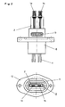
- Thin-film measuring elements 1a and 1b are arranged in the exhaust pipe 7.
- the thin-film measuring elements 1a and 1b are each parts of sheet resistors which are fastened in recesses of a ceramic carrier 2 and whose wires 3 are inserted in grooves of the ceramic carrier 2 designed as a plate.
- the wires 3 are remelted in the region of the grooves with a glass mass 4 so that they after cooling the glass melt Contracting so far that they are axially movable within the remaining glass envelope 4.
- the wires 3 of the sheet resistors are electrically connected to the thin-film measuring elements 1 a and 1 b and relieved of strain with a fixing drop 74.
- the wires 3 are sealed with a silicone seal 13 against the housing 8.
- the ceramic carrier 2 is sealed with a silicone gasket 12 against the plastic housing 8 to prevent the entry of media, e.g. B. exhaust gas or soot from the exhaust pipe in the plastic housing 8 to prevent and thus the formation of parallel resistors.
- the plastic housing 8 is an injection molded part made of PPS.
- a metallic shield 6 protects the injection molded part 8 from overheating by the exhaust gas. It remains between the shield 6 and the mounting flange of the exhaust pipe 7, an air gap to prevent contact of the exhaust pipe 7 with the shield 6.
- the injection molded part 8 is mounted on the flange 72 of the exhaust pipe 7 and sealed with an O-ring 9.
- connection lines 11 are sealed in the area of the plastic housing 8 with a seal 14 in order to prevent the entry of media, e.g. As salt water to prevent outside of the exhaust pipe and preclude the formation of parallel resistors by electrically conductive media.
- the seal 14 can be produced by pouring with sealant or by molding in an injection molding machine.
- Fig. 1 protrude from the sheet resistors 1a and 1b, the measuring elements through the slots 73a, 73b of the shield 6. Shielding and film resistors do not touch. Thus, the film resistors are neither mechanically loaded nor thermally coupled. The gap between the measuring element and the shield 6 is kept as low as possible, so that generated in this opening the exhaust gas flowing past the exhaust pipe as little turbulence and therefore the air insulation between the carrier 2 and the shield 6 as little as possible.
- the seals 13 and 14 prevent gas flows, so that the air between the support 2 and the shield 6 acts as a heat-insulating air cushion.
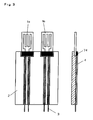
- FIG. 2 The side view of Fig. 2 illustrated without the shield 6 off Fig. 1 how the sheet resistors fastened on the support 2 are arranged with their wires 3 and the support 2 in the injection-molded housing 8 and are sealed with the seal 13.
- the seal 12 can be made by pouring be prepared with sealant. In this way, the carrier is fastened particularly stable in the housing. Furthermore, the seal prevents the entry of media between the carrier and the housing.
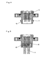
- the sheet resistors 1 a and 1 b according to Fig. 3 consist of a substrate and a thin-film conductor track arranged thereon, which are electrically connected to wires 3.
- the wires 3 are strain-relieved with a fixing drop 74.
- the sheet resistors 1 a and 1 b are arranged with their strain reliefs in recesses of the carrier 2 and the wires 3 of the sheet resistors placed in grooves of the carrier 2.
- a glass envelope 4 is generated, in which the wires are axially movable. For this purpose, both the recess and the grooves are filled with glass paste.
- the wires 3 contract, so that the wires 3 in the glass sheath 4 are axially movable. As a result, stresses due to the different expansion coefficients of glass sheath 4 and wires 3 are avoided.
- connection area is formed with plug contacts 17 and a plastic border with latching hook 16 as a connector.
- An encapsulation of solid contact pins with plastic causes a strain relief of the connections and sealing the like.
- the parts to be inserted into one another are preferably sealed off from one another with a seal.
- the electrical connections 10 can also be embodied as a leadframe in order to widen the spacing of the connecting wires 3 to the spacing of the connection lines 11, without the connecting wires 3 having to be bent apart.
- connection lines 11 connection lines 11.
Landscapes
- Physics & Mathematics (AREA)
- Fluid Mechanics (AREA)
- General Physics & Mathematics (AREA)
- Measuring Volume Flow (AREA)
Applications Claiming Priority (1)
| Application Number | Priority Date | Filing Date | Title |
|---|---|---|---|
| DE102008037206.4A DE102008037206B4 (de) | 2008-08-11 | 2008-08-11 | 300°C-Flowsensor |
Publications (2)
| Publication Number | Publication Date |
|---|---|
| EP2154493A2 true EP2154493A2 (fr) | 2010-02-17 |
| EP2154493A3 EP2154493A3 (fr) | 2014-07-09 |
Family
ID=40935672
Family Applications (1)
| Application Number | Title | Priority Date | Filing Date |
|---|---|---|---|
| EP09008739.6A Withdrawn EP2154493A3 (fr) | 2008-08-11 | 2009-07-03 | Capteur de flux 300°C |
Country Status (4)
| Country | Link |
|---|---|
| US (1) | US7963162B2 (fr) |
| EP (1) | EP2154493A3 (fr) |
| JP (1) | JP5745755B2 (fr) |
| DE (1) | DE102008037206B4 (fr) |
Cited By (4)
| Publication number | Priority date | Publication date | Assignee | Title |
|---|---|---|---|---|
| EP2485018A1 (fr) * | 2011-02-03 | 2012-08-08 | FESTO AG & Co. KG | Dispositif de mesure d'écoulement |
| DE102017203536A1 (de) | 2017-03-03 | 2018-09-06 | Ust Umweltsensortechnik Gmbh | Sensorelement mit Drahtführung |
| US10584987B2 (en) | 2015-09-30 | 2020-03-10 | Hitachi Automotive Systems, Ltd. | Physical quantity detection device |
| US10928232B2 (en) | 2014-11-06 | 2021-02-23 | Hitachi Automotive Systems, Ltd. | Thermal air flow meter |
Families Citing this family (11)
| Publication number | Priority date | Publication date | Assignee | Title |
|---|---|---|---|---|
| US20100170483A1 (en) * | 2007-04-26 | 2010-07-08 | Heraeus Sensor Technology Gmbh | Film resistor in an exhaust-gas pipe |
| KR100994537B1 (ko) * | 2010-06-28 | 2010-11-15 | 금양산업(주) | 선박용 내연기관의 피스톤 냉각 오일의 유량감지를 위한 열량식 유량감지 시스템 |
| DE102011009754A1 (de) * | 2011-01-28 | 2012-08-02 | Heraeus Sensor Technology Gmbh | Strömungssensoren mit Stromdurchführung im Deckel und Sensorspitze als Zwischenprodukt |
| US9400197B2 (en) * | 2011-09-19 | 2016-07-26 | The Regents Of The University Of Michigan | Fluid flow sensor |
| DE102011056127B3 (de) * | 2011-12-07 | 2013-04-18 | Pierburg Gmbh | Vorrichtung zur Bestimmung eines Gasmassenstroms |
| EP2802846B1 (fr) | 2012-01-12 | 2024-06-19 | Micro Motion, Inc. | Dispositif de mesure ayant une enveloppe bandée |
| DE102013110487A1 (de) | 2012-12-14 | 2014-07-17 | Endress + Hauser Flowtec Ag | Thermisches Durchflussmessgerät |
| KR101777192B1 (ko) * | 2016-02-15 | 2017-09-11 | 필즈엔지니어링 주식회사 | 플로우미터 |
| KR101778113B1 (ko) | 2016-10-19 | 2017-09-13 | 필즈엔지니어링 주식회사 | 벤트 아날리시스 기능을 구비하는 플레어가스 시스템 |
| DE202016107242U1 (de) * | 2016-12-21 | 2018-03-22 | Nordson Corp. | Sensoreinrichtung zur Bestimmung eines Massenstroms eines flüssigen Heißschmelzklebstoffes |
| US10274353B2 (en) * | 2017-03-22 | 2019-04-30 | A. O. Smith Corporation | Flow sensor with hot film anemometer |
Citations (2)
| Publication number | Priority date | Publication date | Assignee | Title |
|---|---|---|---|---|
| WO1981000494A1 (fr) | 1979-07-27 | 1981-02-19 | Motorola Inc | Circuit decodeur a igfet utilisant des transistors couples en serie |
| EP0990674A2 (fr) | 1998-10-02 | 2000-04-05 | Takeda Chemical Industries, Ltd. | Procédé pour la décomposition et la récupération d'une résine de polyuréthanne |
Family Cites Families (42)
| Publication number | Priority date | Publication date | Assignee | Title |
|---|---|---|---|---|
| JPS63177023A (ja) * | 1987-01-19 | 1988-07-21 | Nippon Soken Inc | 流量センサ |
| JP2605297B2 (ja) | 1987-09-04 | 1997-04-30 | 株式会社村田製作所 | 白金温度センサおよびその製造方法 |
| DE3804797A1 (de) * | 1988-02-16 | 1989-08-24 | Bosch Gmbh Robert | Luftmassenmessvorrichtung |
| JP2564415B2 (ja) * | 1990-04-18 | 1996-12-18 | 株式会社日立製作所 | 空気流量検出器 |
| JP2839739B2 (ja) * | 1991-03-13 | 1998-12-16 | 日本碍子株式会社 | 抵抗素子 |
| JP2846518B2 (ja) * | 1992-03-18 | 1999-01-13 | 株式会社日立製作所 | 空気流量検出器及びそれを使用したエンジン制御装置 |
| JP2690655B2 (ja) * | 1992-04-28 | 1997-12-10 | 株式会社日立製作所 | 熱式空気流量計 |
| JP3228581B2 (ja) * | 1992-12-24 | 2001-11-12 | 京セラ株式会社 | セラミックヒータ |
| DE59507056D1 (de) | 1994-02-28 | 1999-11-18 | Heraeus Electro Nite Int | Verfahren zur befestigung einer sensoranordnung für heissfilmanemometer |
| DE4407209C2 (de) * | 1994-03-04 | 1996-10-17 | Bosch Gmbh Robert | Vorrichtung zur Messung der Masse eines in einer Leitung strömenden Mediums |
| JPH08219838A (ja) * | 1995-02-15 | 1996-08-30 | Hitachi Ltd | 空気流量測定装置 |
| JP3331814B2 (ja) * | 1995-05-18 | 2002-10-07 | 三菱電機株式会社 | 感熱式流量検出装置 |
| JP3438843B2 (ja) * | 1995-06-14 | 2003-08-18 | 株式会社デンソー | 熱式流量計 |
| US6427668B1 (en) * | 1997-06-26 | 2002-08-06 | Hitachi, Ltd. | Thermal-type airflow meter, intake air system for an internal combustion engine, and control system for the same |
| US6337470B1 (en) * | 1997-10-06 | 2002-01-08 | Watlow Electric Manufacturing Company | Electrical components molded within a polymer composite |
| DE19813468C1 (de) * | 1998-03-26 | 1999-07-22 | Sensotherm Temperatursensorik | Sensorbauelement |
| JP2000028411A (ja) * | 1998-07-08 | 2000-01-28 | Mitsui Mining & Smelting Co Ltd | 流量センサー及び流量検出装置 |
| DE19901184C1 (de) * | 1999-01-14 | 2000-10-26 | Sensotherm Temperatursensorik | Platintemperatursensor und Verfahren zur Herstellung desselben |
| JP3555017B2 (ja) * | 1999-09-22 | 2004-08-18 | 三菱電機株式会社 | 感熱式流量センサ |
| EP1227304A4 (fr) * | 1999-10-29 | 2006-07-12 | Mitsui Mining & Smelting Co | Debitmetre |
| DE19959854A1 (de) * | 1999-12-10 | 2001-06-13 | Heraeus Electro Nite Int | Verfahren zur Abgasrückführung in einem Luftansaugbereich von Fahrzeug-Brennkraftmaschinen sowie Vorrichtung |
| EP1128168A3 (fr) * | 2000-02-23 | 2002-07-03 | Hitachi, Ltd. | Appareil pour la mesure d' une grandeur physique comme l' écoulement d' un fluide |
| JP3825267B2 (ja) * | 2000-02-23 | 2006-09-27 | 株式会社日立製作所 | 流量測定装置、物理検出装置およびエンジンシステム |
| WO2002010694A1 (fr) * | 2000-07-27 | 2002-02-07 | Hitachi, Ltd. | Debitmetre a air de type thermique |
| US6588931B2 (en) * | 2000-12-07 | 2003-07-08 | Delphi Technologies, Inc. | Temperature sensor with flexible circuit substrate |
| US20030002994A1 (en) * | 2001-03-07 | 2003-01-02 | Johnson A. David | Thin film shape memory alloy actuated flow controller |
| JP2002372473A (ja) * | 2001-04-12 | 2002-12-26 | Fuji Electric Co Ltd | 半導体センサ収納容器およびその製造方法、並びに半導体センサ装置 |
| DE10124964B4 (de) * | 2001-05-21 | 2004-02-05 | Forschungszentrum Karlsruhe Gmbh | Sensor zur Messung von Strömungsgeschwindigkeiten und Verfahren zu dessen Betrieb |
| DE10225602A1 (de) * | 2002-06-07 | 2004-01-08 | Heraeus Sensor-Nite Gmbh | Halbleiterbauelement mit integrierter Schaltung, Kühlkörper und Temperatursensor |
| JP4310086B2 (ja) * | 2002-08-01 | 2009-08-05 | 株式会社日立製作所 | エンジン用電子機器 |
| EP1431718A3 (fr) | 2002-12-20 | 2007-11-14 | Heraeus Sensor Technology Gmbh | Capteur de débit utilisant des couches minces et son utilisation |
| DE10314705B3 (de) * | 2003-03-31 | 2004-07-01 | Heraeus Sensor Technology Gmbh | Vorrichtung zur Bestimmung der Temperatur eines strömenden Mediums in einer Rohr- oder Schlauchleitung |
| JP4609019B2 (ja) * | 2004-09-24 | 2011-01-12 | 株式会社デンソー | 熱式流量センサ及びその製造方法 |
| JP2006317295A (ja) * | 2005-05-13 | 2006-11-24 | Hitachi Ltd | 熱式流量計 |
| JP4830391B2 (ja) * | 2005-07-29 | 2011-12-07 | 株式会社デンソー | センサ装置の製造方法及びセンサ装置 |
| EP1760437A1 (fr) * | 2005-09-06 | 2007-03-07 | Sensirion AG | Procédé de fabrication de dispositifs détecteurs |
| EP1941244B1 (fr) | 2005-10-24 | 2015-01-28 | Heraeus Sensor Technology Gmbh | Élément capteur de flux et autonettoyage de celui-ci |
| DE102006030786A1 (de) | 2006-06-30 | 2008-01-03 | Heraeus Sensor Technology Gmbh | Strömungssensorelement und dessen Selbstreinigung |
| DE102005061548B4 (de) * | 2005-12-22 | 2007-12-06 | Pierburg Gmbh | Verfahren zum Betreiben eines Abgasmassenstromsensors |
| DE102006058425A1 (de) * | 2006-12-08 | 2008-06-19 | Heraeus Sensor Technology Gmbh | Abgasrückführung mit einem Anemometer |
| US20100170483A1 (en) * | 2007-04-26 | 2010-07-08 | Heraeus Sensor Technology Gmbh | Film resistor in an exhaust-gas pipe |
| DE202007014129U1 (de) * | 2007-10-09 | 2007-12-13 | Huba Control Ag | Sensor für in Abgase von Verbrennungsmotoren einzuspritzende Harnstofflösung |
-
2008
- 2008-08-11 DE DE102008037206.4A patent/DE102008037206B4/de not_active Expired - Fee Related
-
2009
- 2009-07-03 EP EP09008739.6A patent/EP2154493A3/fr not_active Withdrawn
- 2009-08-10 US US12/538,275 patent/US7963162B2/en not_active Expired - Fee Related
- 2009-08-11 JP JP2009186276A patent/JP5745755B2/ja not_active Expired - Fee Related
Patent Citations (2)
| Publication number | Priority date | Publication date | Assignee | Title |
|---|---|---|---|---|
| WO1981000494A1 (fr) | 1979-07-27 | 1981-02-19 | Motorola Inc | Circuit decodeur a igfet utilisant des transistors couples en serie |
| EP0990674A2 (fr) | 1998-10-02 | 2000-04-05 | Takeda Chemical Industries, Ltd. | Procédé pour la décomposition et la récupération d'une résine de polyuréthanne |
Cited By (5)
| Publication number | Priority date | Publication date | Assignee | Title |
|---|---|---|---|---|
| EP2485018A1 (fr) * | 2011-02-03 | 2012-08-08 | FESTO AG & Co. KG | Dispositif de mesure d'écoulement |
| US10928232B2 (en) | 2014-11-06 | 2021-02-23 | Hitachi Automotive Systems, Ltd. | Thermal air flow meter |
| US10584987B2 (en) | 2015-09-30 | 2020-03-10 | Hitachi Automotive Systems, Ltd. | Physical quantity detection device |
| DE102017203536A1 (de) | 2017-03-03 | 2018-09-06 | Ust Umweltsensortechnik Gmbh | Sensorelement mit Drahtführung |
| DE102017203536B4 (de) * | 2017-03-03 | 2021-04-01 | Ust Umweltsensortechnik Gmbh | Sensorelement mit Drahtführung |
Also Published As
| Publication number | Publication date |
|---|---|
| EP2154493A3 (fr) | 2014-07-09 |
| US20100031742A1 (en) | 2010-02-11 |
| JP2010044071A (ja) | 2010-02-25 |
| JP5745755B2 (ja) | 2015-07-08 |
| DE102008037206A1 (de) | 2010-03-04 |
| US7963162B2 (en) | 2011-06-21 |
| DE102008037206B4 (de) | 2014-07-03 |
Similar Documents
| Publication | Publication Date | Title |
|---|---|---|
| DE102008037206B4 (de) | 300°C-Flowsensor | |
| DE112013001060B4 (de) | Thermische Luftmengenmesseinrichtung | |
| EP2492649A1 (fr) | Capteur d'écoulement doté d'un passage de courant dans le couvercle du boitier du capteur et pointe de sonde en tant que produit intermédiaire | |
| EP2255160B1 (fr) | Capteur de debit du type thermique | |
| EP1941244B1 (fr) | Élément capteur de flux et autonettoyage de celui-ci | |
| DE102007057221B4 (de) | Durchflussmengenmessvorrichtung | |
| DE102006034248B3 (de) | Temperaturfühler für ein Widerstandsthermometer, insbesondere zur Verwendung im Abgasstrang von Verbrennungsmotoren | |
| DE112015003303B4 (de) | Temperatursensor | |
| WO2008131890A2 (fr) | Résistance à couche dans un tuyau d'échappement | |
| WO2008000494A2 (fr) | Résistance à couche contenue dans le tuyau d'échappement | |
| DE112013002966B4 (de) | Thermischer Durchflussmesser | |
| DE102004007906B4 (de) | Keramisch isolierter Hochtemperatursensor | |
| DE102010028267A1 (de) | Vorrichtung zur Erfassung einer Eigenschaft eines strömenden fluiden Mediums | |
| DE102009060363A1 (de) | Verbindungseinheit | |
| EP2909593B1 (fr) | Capteur de température et débitmètre thermique | |
| DE102007011535B4 (de) | Hochtemperatursensor | |
| EP2850308B1 (fr) | Capteur d'oxygen et moteur à combustion interne comprenant un tel capteur | |
| DE112013002992T5 (de) | Thermischer Durchflussmesser | |
| DE69819850T2 (de) | Elektrische vorrichtung mit atmosphärischer isolation | |
| DE202013103402U1 (de) | Temperatursensor und thermisches Durchflussmessgerät | |
| DE102007041109B4 (de) | Fluidmassenmesser | |
| DE102008010206B4 (de) | Hochtemperatursensor | |
| DE102009011750B3 (de) | Temperaturfühler für einen Zylinderkopf eines Motors | |
| WO2013007648A2 (fr) | Dispositif capteur de mesure haute température | |
| EP4379794B1 (fr) | Dispositif de support à caloduc pulsé, module de puissance et produit de programme informatique |
Legal Events
| Date | Code | Title | Description |
|---|---|---|---|
| PUAI | Public reference made under article 153(3) epc to a published international application that has entered the european phase |
Free format text: ORIGINAL CODE: 0009012 |
|
| 17P | Request for examination filed |
Effective date: 20090715 |
|
| AK | Designated contracting states |
Kind code of ref document: A2 Designated state(s): AT BE BG CH CY CZ DE DK EE ES FI FR GB GR HR HU IE IS IT LI LT LU LV MC MK MT NL NO PL PT RO SE SI SK SM TR |
|
| AX | Request for extension of the european patent |
Extension state: AL BA RS |
|
| PUAL | Search report despatched |
Free format text: ORIGINAL CODE: 0009013 |
|
| AK | Designated contracting states |
Kind code of ref document: A3 Designated state(s): AT BE BG CH CY CZ DE DK EE ES FI FR GB GR HR HU IE IS IT LI LT LU LV MC MK MT NL NO PL PT RO SE SI SK SM TR |
|
| AX | Request for extension of the european patent |
Extension state: AL BA RS |
|
| RIC1 | Information provided on ipc code assigned before grant |
Ipc: G01F 1/692 20060101ALI20140602BHEP Ipc: F02M 25/07 20060101ALI20140602BHEP Ipc: G01F 1/684 20060101AFI20140602BHEP |
|
| 17Q | First examination report despatched |
Effective date: 20170428 |
|
| STAA | Information on the status of an ep patent application or granted ep patent |
Free format text: STATUS: THE APPLICATION IS DEEMED TO BE WITHDRAWN |
|
| 18D | Application deemed to be withdrawn |
Effective date: 20180526 |