EP2909593B1 - Capteur de température et débitmètre thermique - Google Patents
Capteur de température et débitmètre thermique Download PDFInfo
- Publication number
- EP2909593B1 EP2909593B1 EP13771090.1A EP13771090A EP2909593B1 EP 2909593 B1 EP2909593 B1 EP 2909593B1 EP 13771090 A EP13771090 A EP 13771090A EP 2909593 B1 EP2909593 B1 EP 2909593B1
- Authority
- EP
- European Patent Office
- Prior art keywords
- temperature sensor
- board
- housing
- housing chamber
- previous
- Prior art date
- Legal status (The legal status is an assumption and is not a legal conclusion. Google has not performed a legal analysis and makes no representation as to the accuracy of the status listed.)
- Active
Links
- 238000005259 measurement Methods 0.000 title description 6
- 239000010409 thin film Substances 0.000 claims description 8
- 239000000463 material Substances 0.000 claims description 7
- 229920001296 polysiloxane Polymers 0.000 claims description 7
- 150000001875 compounds Chemical class 0.000 claims description 5
- 238000004382 potting Methods 0.000 claims description 5
- 238000011156 evaluation Methods 0.000 claims description 3
- 230000002787 reinforcement Effects 0.000 claims 3
- 238000004026 adhesive bonding Methods 0.000 claims 1
- 239000010410 layer Substances 0.000 description 15
- 238000010438 heat treatment Methods 0.000 description 14
- 239000004020 conductor Substances 0.000 description 7
- 230000003014 reinforcing effect Effects 0.000 description 6
- 239000007788 liquid Substances 0.000 description 4
- 229910052751 metal Inorganic materials 0.000 description 4
- 239000002184 metal Substances 0.000 description 4
- 238000003856 thermoforming Methods 0.000 description 4
- 238000012546 transfer Methods 0.000 description 4
- 230000015572 biosynthetic process Effects 0.000 description 3
- WABPQHHGFIMREM-UHFFFAOYSA-N lead(0) Chemical compound [Pb] WABPQHHGFIMREM-UHFFFAOYSA-N 0.000 description 3
- 238000011144 upstream manufacturing Methods 0.000 description 3
- 238000001816 cooling Methods 0.000 description 2
- 230000001419 dependent effect Effects 0.000 description 2
- 239000007789 gas Substances 0.000 description 2
- 238000004519 manufacturing process Methods 0.000 description 2
- BASFCYQUMIYNBI-UHFFFAOYSA-N platinum Chemical compound [Pt] BASFCYQUMIYNBI-UHFFFAOYSA-N 0.000 description 2
- 230000003746 surface roughness Effects 0.000 description 2
- 230000007704 transition Effects 0.000 description 2
- XLYOFNOQVPJJNP-UHFFFAOYSA-N water Substances O XLYOFNOQVPJJNP-UHFFFAOYSA-N 0.000 description 2
- 239000004809 Teflon Substances 0.000 description 1
- 229920006362 Teflon® Polymers 0.000 description 1
- 238000005266 casting Methods 0.000 description 1
- 239000000919 ceramic Substances 0.000 description 1
- 230000000295 complement effect Effects 0.000 description 1
- 238000011109 contamination Methods 0.000 description 1
- 230000007423 decrease Effects 0.000 description 1
- 238000013461 design Methods 0.000 description 1
- 230000000694 effects Effects 0.000 description 1
- 238000005485 electric heating Methods 0.000 description 1
- 230000005611 electricity Effects 0.000 description 1
- 239000011521 glass Substances 0.000 description 1
- 238000009434 installation Methods 0.000 description 1
- 238000009413 insulation Methods 0.000 description 1
- 238000000034 method Methods 0.000 description 1
- 238000010327 methods by industry Methods 0.000 description 1
- 229910052697 platinum Inorganic materials 0.000 description 1
- 239000011241 protective layer Substances 0.000 description 1
- 238000009420 retrofitting Methods 0.000 description 1
- 230000035945 sensitivity Effects 0.000 description 1
- 238000005476 soldering Methods 0.000 description 1
- 239000000126 substance Substances 0.000 description 1
- 239000000758 substrate Substances 0.000 description 1
- 238000003466 welding Methods 0.000 description 1
Images
Classifications
-
- G—PHYSICS
- G01—MEASURING; TESTING
- G01K—MEASURING TEMPERATURE; MEASURING QUANTITY OF HEAT; THERMALLY-SENSITIVE ELEMENTS NOT OTHERWISE PROVIDED FOR
- G01K7/00—Measuring temperature based on the use of electric or magnetic elements directly sensitive to heat ; Power supply therefor, e.g. using thermoelectric elements
- G01K7/16—Measuring temperature based on the use of electric or magnetic elements directly sensitive to heat ; Power supply therefor, e.g. using thermoelectric elements using resistive elements
-
- G—PHYSICS
- G01—MEASURING; TESTING
- G01F—MEASURING VOLUME, VOLUME FLOW, MASS FLOW OR LIQUID LEVEL; METERING BY VOLUME
- G01F1/00—Measuring the volume flow or mass flow of fluid or fluent solid material wherein the fluid passes through a meter in a continuous flow
- G01F1/68—Measuring the volume flow or mass flow of fluid or fluent solid material wherein the fluid passes through a meter in a continuous flow by using thermal effects
- G01F1/684—Structural arrangements; Mounting of elements, e.g. in relation to fluid flow
-
- G—PHYSICS
- G01—MEASURING; TESTING
- G01F—MEASURING VOLUME, VOLUME FLOW, MASS FLOW OR LIQUID LEVEL; METERING BY VOLUME
- G01F1/00—Measuring the volume flow or mass flow of fluid or fluent solid material wherein the fluid passes through a meter in a continuous flow
- G01F1/68—Measuring the volume flow or mass flow of fluid or fluent solid material wherein the fluid passes through a meter in a continuous flow by using thermal effects
- G01F1/684—Structural arrangements; Mounting of elements, e.g. in relation to fluid flow
- G01F1/688—Structural arrangements; Mounting of elements, e.g. in relation to fluid flow using a particular type of heating, cooling or sensing element
- G01F1/69—Structural arrangements; Mounting of elements, e.g. in relation to fluid flow using a particular type of heating, cooling or sensing element of resistive type
-
- G—PHYSICS
- G01—MEASURING; TESTING
- G01F—MEASURING VOLUME, VOLUME FLOW, MASS FLOW OR LIQUID LEVEL; METERING BY VOLUME
- G01F1/00—Measuring the volume flow or mass flow of fluid or fluent solid material wherein the fluid passes through a meter in a continuous flow
- G01F1/68—Measuring the volume flow or mass flow of fluid or fluent solid material wherein the fluid passes through a meter in a continuous flow by using thermal effects
- G01F1/684—Structural arrangements; Mounting of elements, e.g. in relation to fluid flow
- G01F1/688—Structural arrangements; Mounting of elements, e.g. in relation to fluid flow using a particular type of heating, cooling or sensing element
- G01F1/69—Structural arrangements; Mounting of elements, e.g. in relation to fluid flow using a particular type of heating, cooling or sensing element of resistive type
- G01F1/692—Thin-film arrangements
-
- G—PHYSICS
- G01—MEASURING; TESTING
- G01F—MEASURING VOLUME, VOLUME FLOW, MASS FLOW OR LIQUID LEVEL; METERING BY VOLUME
- G01F1/00—Measuring the volume flow or mass flow of fluid or fluent solid material wherein the fluid passes through a meter in a continuous flow
- G01F1/68—Measuring the volume flow or mass flow of fluid or fluent solid material wherein the fluid passes through a meter in a continuous flow by using thermal effects
- G01F1/696—Circuits therefor, e.g. constant-current flow meters
-
- G—PHYSICS
- G01—MEASURING; TESTING
- G01F—MEASURING VOLUME, VOLUME FLOW, MASS FLOW OR LIQUID LEVEL; METERING BY VOLUME
- G01F15/00—Details of, or accessories for, apparatus of groups G01F1/00 - G01F13/00 insofar as such details or appliances are not adapted to particular types of such apparatus
- G01F15/14—Casings, e.g. of special material
-
- G—PHYSICS
- G01—MEASURING; TESTING
- G01K—MEASURING TEMPERATURE; MEASURING QUANTITY OF HEAT; THERMALLY-SENSITIVE ELEMENTS NOT OTHERWISE PROVIDED FOR
- G01K1/00—Details of thermometers not specially adapted for particular types of thermometer
- G01K1/08—Protective devices, e.g. casings
-
- G—PHYSICS
- G01—MEASURING; TESTING
- G01K—MEASURING TEMPERATURE; MEASURING QUANTITY OF HEAT; THERMALLY-SENSITIVE ELEMENTS NOT OTHERWISE PROVIDED FOR
- G01K7/00—Measuring temperature based on the use of electric or magnetic elements directly sensitive to heat ; Power supply therefor, e.g. using thermoelectric elements
- G01K7/16—Measuring temperature based on the use of electric or magnetic elements directly sensitive to heat ; Power supply therefor, e.g. using thermoelectric elements using resistive elements
- G01K7/18—Measuring temperature based on the use of electric or magnetic elements directly sensitive to heat ; Power supply therefor, e.g. using thermoelectric elements using resistive elements the element being a linear resistance, e.g. platinum resistance thermometer
-
- G—PHYSICS
- G01—MEASURING; TESTING
- G01D—MEASURING NOT SPECIALLY ADAPTED FOR A SPECIFIC VARIABLE; ARRANGEMENTS FOR MEASURING TWO OR MORE VARIABLES NOT COVERED IN A SINGLE OTHER SUBCLASS; TARIFF METERING APPARATUS; MEASURING OR TESTING NOT OTHERWISE PROVIDED FOR
- G01D11/00—Component parts of measuring arrangements not specially adapted for a specific variable
- G01D11/24—Housings ; Casings for instruments
- G01D11/245—Housings for sensors
Definitions
- the invention relates to a temperature sensor and a thermal flow meter
- thermometer hereinafter also referred to as heating and measuring or active sensor element, which is withdrawn by the passing medium heat.
- the extracted energy is compensated by increasing the electric heating current again.
- a constant temperature difference between the heating and measuring sensor element, ie the active sensor element, and an existing reference temperature sensor, which is also referred to below as a measuring or passive sensor element is established.
- the measured heating current is therefore proportional to the mass flow.
- the thermal measuring principle is well established in process engineering and is used successfully in numerous applications.
- Sensors consist of two sensor elements, a heating and a measuring sensor element, each having a cylindrical sensor cap and protrude from a base of a sensor.
- resistance sensors are soldered. Due to the cylindrical sensor caps, the sensor elements already have a good thermal insulation. However, these sensors have a worse characteristic in water than the aforementioned sensors.
- the characteristic curve reaches a saturation level comparatively quickly, at which a maximum power can be fed in. When this power limit is reached, no heat can be added to the flow despite the higher speed. Since the characteristic curve represents the measuring range for the flow velocity of the medium up to which a measurement can take place, if the degree of saturation is reached quickly, it is no longer possible to measure at too fast a flow.
- connection concepts for RTD's in sensor housings are common, which are known on mounting the RTD's in sleeves. Their connecting wires are made from the sleeves.
- the font US7293457B2 teaches a thermal flow meter, in which a temperature sensing element is connected to a circuit board, which board is arranged in a recess of a circuit board housing and glued there.
- the object of the present invention is to allow easier mounting of the temperature sensor, and to provide a corresponding flow meter This object is achieved by a temperature sensor with the features of claim 1 and by a thermal flow meter according to claim 14.
- a temperature sensor with a housing comprising a housing body and a housing chamber in each housing chamber terminal two temperature sensor elements, which are in particular designed as a thin-film resistance thermometer, are arranged, wherein one of the temperature sensor elements is heated, leaving at least one lead wire of each temperature sensor elements, which is connected to a circuit board, wherein the circuit board is arranged in the housing chamber, wherein the circuit board is positioned by a latching connection in this housing chamber, wherein a lead wire of a first temperature sensing element zugentlastend in a first direction and a lead wire of a second temperature sensing element zugentlastend in one of the first direction opposite second direction through the board and connected to it.
- the positioning of the board in the housing chamber by means of a latching connection makes it easier to assemble. Due to the two-sided strain relief of the connecting wires, cables or four-conductor cables can be routed away from the board on both sides and accordingly a mounting advantage can be achieved.
- Advantageous embodiments of the invention are the subject of the dependent claims. It is advantageous if the housing chamber has a reinforcing layer, which reinforcing layer has an engagement, or a depression, or a projection for latching to the circuit board.
- a terminal part of the housing is designed as a deep-drawn cap with a wall thickness of less than 2 mm, preferably less than 1.5 mm, in particular less than 0.8 mm.
- a material connection of both components can be carried out, for example by welding or soldering.
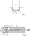
- Fig. 1 shows a sensor of a thermal flow meter, which is designed as a thermal mass flow sensor 1.
- thermometers configured as identically as possible, which are arranged in, usually pin-shaped metal sleeves, so-called stingers, or in cylindrical metal sleeves and which are in thermal contact with the medium flowing through a measuring tube or through the pipeline.
- both resistance thermometers are usually installed in a measuring tube;
- the resistance thermometers can also be mounted directly in the pipeline.
- One of the two resistance thermometers is a so-called active sensor element, which is heated by means of a heating unit.
- a heating unit either an additional resistance heating is provided, or the resistance thermometer itself is a resistance element, for. B. to an RTD (Resistance Temperature Device) sensor, the by converting an electrical power, for. B. is heated by a corresponding variation of the measuring current.
- the second resistance thermometer is a so-called passive sensor element: it measures the temperature of the medium.
- thermometer in a thermal flow meter, a heatable resistance thermometer is heated so that sets a fixed temperature difference between the two resistance thermometer.
- it has also become known to feed a constant heat output via a control / control unit.
- the cooling of the heated resistance thermometer depends essentially on the mass flow rate of the flowing medium. Since the medium is colder than the heated resistance thermometer, heat is removed from the heated resistance thermometer by the passing medium. Thus, in order to maintain the fixed temperature difference between the two resistance thermometers in a flowing medium, an increased heating power for the heated resistance thermometer is required.
- the increased heating power is a measure of the mass flow or the mass flow of the medium through the pipeline.
- the temperature difference between the two resistance thermometers decreases as a result of the flow of the medium.
- the respective temperature difference is then a measure of the Mass flow of the medium through the pipe or through the measuring tube.
- thermometer there is a functional relationship between the heating energy necessary for heating the resistance thermometer and the mass flow through a pipeline or through a measuring tube.
- the dependence of the heat transfer coefficient on the mass flow of the medium through the measuring tube or through the pipeline is used in thermal flowmeters for determining the mass flow.
- Devices based on this principle are offered and distributed by the applicant under the name 't-switch', 't-trend' or 't-mass'.
- a thermal flow meter When determining the thermal mass flow, a thermal flow meter can reach a maximum performance limit when measuring liquids. Since liquids have a significantly higher coefficient of thermal conductivity than gases, greater heat energy is removed from the surface of the active temperature sensor at higher speeds. As the velocity of the medium increases, saturation or the upper limit of the resistance of the resistance thermometer is reached quickly, so that the measuring range is limited to liquids with low flow velocities. This disadvantage is due to a sensor of a thermal flow meter, as it is in Fig. 1-2 is pictured, fixed.
- Fig. 1 shows a sensor 1 for a thermal flow meter.
- This sensor 1 has a sensor body 2 with a cylindrical shape and with a longitudinal axis A and a terminal end face 3 with a center M, through which the longitudinal axis A extends on.
- This cylindrical sensor body has an average d between preferably 10-30 mm, in particular between 15 - 22 mm and also has an inner housing chamber.
- This end face 3 is divided into several segments 3a-3c. The segments are arranged side by side with a first side segment 3a, a middle segment 3b and a second side segment 3c.
- At least a first side segment in the sectional view of Fig. 1 is formed as a surface inclined with respect to the longitudinal axis A whose surface normal vector encloses an angle ⁇ of preferably at least 5 °, preferably at least 8 °, particularly preferably between 10-35 ° with the longitudinal axis.
- the surface may be formed in particular flat, have unevenness due to surface roughness or run in an arc shape towards the measuring medium or away from the measuring medium.
- This first side segment 3 a is preferably a side segment whose inclined surface is inclined in the direction of the inflow side of the sensor 1, that is, opposite to the flow direction S.
- a first temperature sensor element which in the present case is designed as a resistance thermometer 4, is arranged, the structure of which will be described in more detail below with reference to an exemplary embodiment.
- This resistance thermometer 4 is preferably formed as a thin-film element.
- the resistance thermometer 4 has a three-layer structure, with a ceramic substrate, a meander-shaped metal layer, preferably of platinum, and a glass protective layer arranged above it. From the metal wire go from a supply and a derivative. The temperature is measured by taking advantage of the temperature dependence of an electrical resistance in the conduction of electricity. In this operating state, the resistance thermometer 4 can be used as a passive sensor element.
- the above-described resistance thermometer 4 measures as a passive sensor element, the medium temperature and brings as an active sensor element under adjustment of the current even a quantity of heat in the medium.
- the resistance thermometer 4 of the first side segment 3a is an active sensor element which has a constant temperature and emits heat energy to the passing medium.
- This sensor element or resistance thermometer 4 is preferably designed as a thin-film element plate-shaped.
- the plate-shaped thin-film element is aligned substantially parallel to the surface of the first side segment 3a. Smaller deviations of less than 10 °, preferably less than 5 ° to the parallel plane can occur here.
- the first resistance thermometer 4 which is arranged on or below the first side segment 3a, is operated as an active sensor element.
- the upstream side element 3a is the segment of the end face 3, on which the flow of the medium in the flow direction S first meets.
- a second temperature element which is designed as a resistance thermometer 5 is preferably arranged in the sensor 1 below the second side segment 3c.
- this second resistance thermometer 5 acts as a passive resistance thermometer for detecting the medium temperature.
- the middle segment 3b has a surface with a surface normal vector which runs along the longitudinal axis. Smaller deviations of less than 1 °, preferably less than 0.5 ° to the parallel plane can occur here.
- the second side segment in the sectional view of Fig. 1 is formed as a surface inclined with respect to the longitudinal axis A, whose surface normal vector encloses with the longitudinal axis A an angle ⁇ of preferably at least 5 °, preferably at least 8 °, particularly preferably between 10-35 °.
- the surface may be formed in particular flat, have unevenness due to surface roughness or run in an arc shape towards the measuring medium or away from the measuring medium.
- This second side segment 3c is preferably a side segment whose inclined surface is inclined in the flow direction S of the measurement medium.
- the inclination of the first upstream side segment 3a causes a reduction of the thermal boundary layer thickness compared to a planar surface, however, the formation of a comparatively uniformly distributed over the surface tight boundary layer takes place.
- this boundary layer the heat output of the active sensor element is reduced.
- the presence of the boundary layer reduces the temperature gradient between the medium and the sensor surface, which requires less heat input. Due to the boundary layer, the sensor requires less power during measurement operation.
- the second resistance thermometer 5 of the downstream side second segment 3c is operated as an active sensor element and the first resistance thermometer 4 of the upstream side segment 3a is operated as a passive sensor element.
- a boundary layer structure is formed over the entire end face 3 of the sensor and is present in a particularly high layer thickness in the downstream region.
- This boundary layer allows, as already described in the preceding embodiment, a lower heat input into the medium and thus a delay of the degree of saturation to higher flow velocities of the medium.
- a trailing edge is also created, at which the flow breaks off at higher speeds.
- a recirculation is built up at an increased speed of the medium, ie a flow which is at least partially directed counter to the main flow direction.
- This recirculation is slower, preferably at least 20% slower, more preferably at least 40% slower than the main flow, but behaves proportionally to the main flow.
- the part of the recirculation directed counter to the main flow passes in the medium direction below the transition or below the trailing edge past the second downstream side segment and absorbs a lower heat energy than would be the case with the main flow. As a result, less power is needed to maintain the temperature and a power saturation occurs only at very high flow rates.
- the optimized geometry of the sensor based on two different phenomena, the formation of a flow rate-dependent recirculation in the outflow at high speeds and the formation of a uniform boundary layer in the onflow region.
- the new sensor geometry provides more stable and reliable measurements than previous geometries.
- the end face is placed as a cap on a cylindrical sensor, so that the cap is easily replaceable in case of contamination.
- these caps can also be placed on existing sensors, in particular with ebender end face, so that a retrofitting of existing sensors is possible.
- the Biotress which describes the heat transfer from the surface to the surrounding medium for heat conduction through the body, is reduced due to the boundary layer compared to a sensor with a predominantly flat end face.
- the face can also advantageously have a web in measuring tubes with small diameters, which runs in the flow direction of the medium.
- This bar is particularly advantageous for measuring tubes with smaller nominal diameters, since there is less stagnation of the medium at the sensor and lower pressure losses.
- a resistance thermometer (RTD) 4 or 5 are used in parallel to one of the side segments 3a and 3c, of which at least one resistance thermometer is heatable and which are formed in the present embodiment as a thin-film resistance thermometer.
- RTD resistance thermometer
- the resistance thermometer is soldered on the inside of the housing 1 in the housing chamber. From the resistance thermometer 4 or 5 in each case two signal paths go here in the form of connecting wires 23, which are preferably gold-plated. These connecting wires connect the thin-film resistance thermometer to a circuit board 25.
- the connecting wires of the first of the two resistance thermometers are arranged in a first direction in the circuit board 25 and the connecting wires of the second of the two resistance thermometers are arranged on or in the first direction opposite to the second direction on or in the circuit board 25.
- Terminal in the region of the front side of the housing body is advantageously formed by a thermoforming cap with a small wall thickness of preferably between 0.5 to 2 mm.
- a rapid heat transfer between the resistance thermometer 4 or 5 and the medium is made possible.
- the connecting wires are initially guided along each of the outer side of the housing chamber. Subsequently, the connecting wires 23 become a circuit board 25 guided and zugentlastend attached to this board 25. The zugentlastende attachment of the leads facilitates the installation of the temperature sensor In the area between the thin-film resistance thermometer and the board, the connecting wires are preferably sheathed with a Teflon hose, not shown.
- the circuit board 25 has lateral locking elements, which can engage with an engagement 29 of the housing 1 or alternatively a projection of the housing. Overall, by specifying the position of the board in the housing faster assembly.
- a reinforcing element with an engagement is arranged in the housing chamber on the wall of the thermoforming cap.
- the housing 1 may also have latching elements which can latch with an engagement or projection of the circuit board 25. These locking elements are also provided by a reinforcing element, which is arranged on the thermoforming cap.
- the housing chamber of the temperature sensor is terminally filled between the board of the housing wall with the resistance thermometers mounted thereon with silicone bodies 21, 22.
- the silicone bodies develop restoring forces, which act on the circuit board 25 and enable a more effective latching.
- the circuit board is preferably located on at least one of the silicone bodies.
- the zugentlastende attachment or connection of the leads 23 to the board 25 will be explained in more detail. It is carried out such that the connecting wires are passed through a first hole in the circuit board 25, then guided in a direction perpendicular to the hole pattern of the first hole and then guided in a direction parallel to the hole pattern on the board and fixed. Thus, the attachment to a wall of the board, which is parallel to the first hole. Thus, the leads are inserted in a first direction A in the hole of the board and fixed in a second direction B, which is opposite to the first direction A, to the board.
- Such zugentlastende arrangements on boards are already known from other applications and serve a permanent attachment of leads to a circuit board.
- the strain relief of the connecting wires only serves a better stability of the connection before and during the casting.
- the above-mentioned mechanical measures for improving the attachment of the board and the connecting wires attached thereto, the reject rate in the production and the failure rate of the temperature sensor in operation will be significantly reduced.
- the aforementioned connection concept can basically be applied to all known multi-conductor measuring techniques of thermal flow measurement.
Landscapes
- Physics & Mathematics (AREA)
- General Physics & Mathematics (AREA)
- Fluid Mechanics (AREA)
- Measuring Volume Flow (AREA)
Claims (14)
- Capteur de température avec un boîtier (1) comprenant un corps de boîtier et une chambre de boîtier, dans laquelle sont disposés en son extrémité deux éléments de sonde de température, lesquels sont conçus notamment sous la forme d'un thermomètre à résistance à couche mince (4 ou 5), l'un des éléments de sonde de température étant chauffant, au moins un fil de raccordement (23) partant de chaque élément de sonde de température, lequel fil est relié avec une platine (25),
pour lequel
la platine (25) est disposée dans la chambre de boîtier,
caractérisé
en ce que la platine (25) est positionnée dans cette chambre de boîtier au moyen d'une liaison par enclenchement, un fil de raccordement (23a) - muni d'une décharge de traction - d'un premier élément de sonde de température étant guidé dans une première direction et un fil de raccordement (23b) - muni d'une décharge de traction - d'un deuxième élément de sonde de température étant guidé dans une deuxième direction opposée à la premier direction à travers la platine (25), et reliés à cette dernière. - Capteur de température selon la revendication 1, caractérisé en ce que la chambre de boîtier comporte une couche de renfort (31), laquelle couche présente ou forme une prise ou une saillie pour l'enclenchement de la platine (25).
- Capteur de température selon la revendication 1 ou 2, caractérisé en ce qu'une partie d'extrémité du boîtier est conçue en tant que capuchon d'emboutissage d'une épaisseur de paroi de moins de 2 mm, de préférence de moins de 1,5 mm et particulièrement de préférence de moins de 0,8 mm.
- Capteur de température selon l'une des revendications précédentes, caractérisé en ce que la couche de renfort (31) est appliquée par adhérence sur le corps de boîtier.
- Capteur de température selon la revendication 4, caractérisé en ce que le fil de raccordement (23a) du premier élément de sonde de température est entouré d'une masse d'enrobage dans la zone de la platine (25).
- Capteur de température selon l'une des revendications précédentes, caractérisé en ce qu'est disposé dans la chambre de boîtier un premier corps élastique (21) destiné à guider le fil de raccordement (23).
- Capteur de température selon la revendication 5, caractérisé en ce qu'est disposé dans la chambre de boîtier un deuxième corps élastique (22), lequel s'appuie sur le premier corps élastique (21) et/ou sur une paroi du boîtier (1), et lequel exerce une force de rappel sur la platine (25) enclenchée.
- Capteur de température selon la revendication 5 ou 6, caractérisé en ce que le premier corps élastique (21) est prévu pour réduire les contraintes thermiques et mécaniques du fil de raccordement (23) en cas de charge de traction.
- Capteur de température selon l'une des revendications précédentes, caractérisé en ce que la chambre de boîtier comporte une masse d'enrobage, les éléments de sonde de température étant disposés sans masse d'enrobage dans la chambre de boîtier.
- Capteur de température selon l'une des revendications précédentes, caractérisé en ce que le premier et le deuxième corps (21, 22) sont des corps en silicone.
- Capteur de température selon l'une des revendications précédentes, caractérisé en ce que la platine (25) présente un premier nombre d'évidements de matière, notamment des trous, destinés au raccordement de fils et/ou de câbles, et un deuxième nombre d'évidements de matière, notamment des trous, destinés à réduire la dilatation thermique de la platine (25).
- Capteur de température selon la revendication 11, caractérisé en ce que les évidements de matière, notamment les trous, sont disposés dans les bandes de cuivre disposées sur la platine (25).
- Capteur de température selon l'une des revendications précédentes, caractérisé en ce que le capteur de température est conçu en tant qu'appareil de mesure à 4 fils.
- Débitmètre thermique comprenant un capteur de température selon l'une des revendications précédentes, ainsi qu'une unité d'exploitation.
Applications Claiming Priority (3)
| Application Number | Priority Date | Filing Date | Title |
|---|---|---|---|
| DE202012104039 | 2012-10-19 | ||
| DE202013103404U DE202013103404U1 (de) | 2012-10-19 | 2013-07-29 | Temperatursensor und Thermisches Durchflussmessgerät |
| PCT/EP2013/069680 WO2014060186A2 (fr) | 2012-10-19 | 2013-09-23 | Capteur de température et débitmètre thermique |
Publications (2)
| Publication Number | Publication Date |
|---|---|
| EP2909593A2 EP2909593A2 (fr) | 2015-08-26 |
| EP2909593B1 true EP2909593B1 (fr) | 2018-02-21 |
Family
ID=49210313
Family Applications (1)
| Application Number | Title | Priority Date | Filing Date |
|---|---|---|---|
| EP13771090.1A Active EP2909593B1 (fr) | 2012-10-19 | 2013-09-23 | Capteur de température et débitmètre thermique |
Country Status (5)
| Country | Link |
|---|---|
| US (1) | US9810586B2 (fr) |
| EP (1) | EP2909593B1 (fr) |
| CN (1) | CN104736980B (fr) |
| DE (1) | DE202013103404U1 (fr) |
| WO (1) | WO2014060186A2 (fr) |
Families Citing this family (7)
| Publication number | Priority date | Publication date | Assignee | Title |
|---|---|---|---|---|
| DE102013223913A1 (de) * | 2013-11-22 | 2015-05-28 | Zf Friedrichshafen Ag | Sensorvorrichtung und Verfahren zum Herstellen einer Sensorvorrichtung |
| DE102016111701A1 (de) * | 2016-06-27 | 2017-12-28 | Endress+Hauser Flowtec Ag | Sensor für ein thermisches Durchflussmessgerät, ein thermisches Durchflussmessgerät und ein Verfahren zum Herstellen eines Sensors eines thermischen Durchflussmessgeräts |
| DE102016114963B3 (de) * | 2016-08-11 | 2018-01-11 | Endress+Hauser Flowtec Ag | Sensor für ein thermisches Durchflussmessgerät, ein thermisches Durchflussmessgerät und ein Verfahren zum Herstellen eines Sensors eines thermischen Durchflussmessgeräts |
| DE202018100186U1 (de) * | 2018-01-15 | 2018-01-26 | Sensirion Automotive Solutions Ag | Sensormodul zur Luftgütemessung |
| CN108489621B (zh) * | 2018-03-09 | 2019-12-31 | Abb瑞士股份有限公司 | 用于测量导体的温度的设备 |
| CN110231107A (zh) * | 2019-04-02 | 2019-09-13 | 马鞍山市嘉逸科技工贸有限责任公司 | 一种组合式高精度温度传感器 |
| DE102020122803A1 (de) * | 2020-09-01 | 2022-03-03 | Endress+Hauser Flowtec Ag | Messgerät |
Citations (2)
| Publication number | Priority date | Publication date | Assignee | Title |
|---|---|---|---|---|
| EP1757916A1 (fr) * | 2005-08-01 | 2007-02-28 | Nexans | Dispositif pour surveiller la température locale |
| DE202009011309U1 (de) * | 2009-08-19 | 2010-09-23 | Messtechnik Ges. M.B.H. & Co. Kg | Vorrichtung zum elektrischen Erfassen der Wärmeabgabe eines Heizkörpers |
Family Cites Families (18)
| Publication number | Priority date | Publication date | Assignee | Title |
|---|---|---|---|---|
| US4135396A (en) * | 1978-04-24 | 1979-01-23 | The Trane Company | Temperature compensating fluid velocity sensing apparatus |
| DE7832695U1 (de) | 1978-11-03 | 1980-04-10 | Bosch-Siemens Hausgeraete Gmbh, 7000 Stuttgart | Temperaturfuehler |
| US4476720A (en) | 1982-06-14 | 1984-10-16 | Cambridge Aero Instruments, Inc. | Unidirectional fluidflow sensor system |
| DE4233284C2 (de) * | 1992-10-02 | 1997-01-30 | Kobold Klaus | Kalorimetrischer Strömungswächter |
| FR2713764B1 (fr) | 1993-11-10 | 1996-01-12 | Ksb Sa | Dispositif de mesure d'un fluide. |
| DE19504608C2 (de) | 1995-02-11 | 2002-03-21 | Balluff Gebhard Feinmech | Positionssensor und Verfahren zur Herstellung desselben |
| DE19512111C2 (de) * | 1995-04-03 | 1999-01-07 | Ifm Electronic Gmbh | Wärmeübergangskontroll- und/oder -meßgerät |
| JPH08330720A (ja) | 1995-05-29 | 1996-12-13 | Temic Telefunken Microelectron Gmbh | 絶縁された線材をはんだ付けする方法 |
| DE19719010C2 (de) | 1996-05-24 | 2003-04-30 | Ifm Electronic Gmbh | Wärmeübergangskontroll- und/oder -meßgerät |
| JPH11351975A (ja) | 1998-06-08 | 1999-12-24 | Matsushita Electric Ind Co Ltd | サーミスタ温度センサ |
| DE19832533C1 (de) | 1998-07-20 | 1999-11-25 | Pepperl & Fuchs | Verfahren zur Herstellung eines Positionssensors und dergestalt hergestellter Positionssensor |
| JP4020208B2 (ja) * | 2004-11-30 | 2007-12-12 | 三菱電機株式会社 | 流量測定装置 |
| CN2784896Y (zh) | 2005-01-21 | 2006-05-31 | 孙利江 | 一种热量表基表 |
| JP4569831B2 (ja) | 2006-04-12 | 2010-10-27 | 株式会社デンソー | 空気流量測定装置 |
| US7832269B2 (en) | 2007-06-22 | 2010-11-16 | Honeywell International Inc. | Packaging multiple measurands into a combinational sensor system using elastomeric seals |
| DE102010061731A1 (de) | 2010-11-22 | 2012-05-24 | Endress + Hauser Flowtec Ag | Gehäuse eines Temperatursensors, insbesondere eines thermischen Durchflussmessgeräts |
| DE202013103402U1 (de) * | 2012-10-19 | 2013-08-22 | Endress + Hauser Flowtec Ag | Temperatursensor und thermisches Durchflussmessgerät |
| DE102013108099A1 (de) * | 2012-10-19 | 2014-04-24 | Endress + Hauser Flowtec Ag | Thermisches Durchflussmessgerät |
-
2013
- 2013-07-29 DE DE202013103404U patent/DE202013103404U1/de not_active Expired - Lifetime
- 2013-09-23 EP EP13771090.1A patent/EP2909593B1/fr active Active
- 2013-09-23 WO PCT/EP2013/069680 patent/WO2014060186A2/fr not_active Ceased
- 2013-09-23 CN CN201380054363.7A patent/CN104736980B/zh active Active
- 2013-09-23 US US14/436,933 patent/US9810586B2/en not_active Expired - Fee Related
Patent Citations (2)
| Publication number | Priority date | Publication date | Assignee | Title |
|---|---|---|---|---|
| EP1757916A1 (fr) * | 2005-08-01 | 2007-02-28 | Nexans | Dispositif pour surveiller la température locale |
| DE202009011309U1 (de) * | 2009-08-19 | 2010-09-23 | Messtechnik Ges. M.B.H. & Co. Kg | Vorrichtung zum elektrischen Erfassen der Wärmeabgabe eines Heizkörpers |
Also Published As
| Publication number | Publication date |
|---|---|
| WO2014060186A2 (fr) | 2014-04-24 |
| DE202013103404U1 (de) | 2013-08-20 |
| EP2909593A2 (fr) | 2015-08-26 |
| US20150276503A1 (en) | 2015-10-01 |
| CN104736980B (zh) | 2017-06-13 |
| US9810586B2 (en) | 2017-11-07 |
| WO2014060186A3 (fr) | 2014-11-06 |
| CN104736980A (zh) | 2015-06-24 |
Similar Documents
| Publication | Publication Date | Title |
|---|---|---|
| EP2909593B1 (fr) | Capteur de température et débitmètre thermique | |
| EP2909639B1 (fr) | Débitmètre thermique | |
| EP3237851B1 (fr) | Débitmètre du type thermique | |
| EP1182432B1 (fr) | Capteur de débit avec boîtier | |
| DE19964452B4 (de) | Flussratensensor | |
| DE102010019303B4 (de) | Strömungsrate-Messvorrichtung | |
| DE102008000864B4 (de) | Strömungsmessvorrichtung | |
| DE19739949B4 (de) | Durchflußdetektor | |
| EP2491353B1 (fr) | Procédé de mesure du débit et de la direction d'écoulement d'un fluide, et débitmètre du type thermique | |
| DE102010056279B4 (de) | Vortex-Durchflussmessgerät mit optimierter Temperaturerfassung | |
| EP2282179A1 (fr) | Procédé de fabrication d'une sonde de température pour un débitmètre du type thermique | |
| DE19919398B4 (de) | Wärmeempfindlicher Flußratensensor | |
| DE202013103402U1 (de) | Temperatursensor und thermisches Durchflussmessgerät | |
| DE19624493B4 (de) | Temperaturermittlungsgerät und dessen Anwendung in einem Strömungsmessgerät der thermischen Art | |
| DE102009045958A1 (de) | Thermisches Durchflussmessgerät | |
| DE112017000359B4 (de) | Luftdurchflusssensor für lüftergekühlte Systeme | |
| EP2151673A2 (fr) | Procédé et dispositif de mesure de la température | |
| DE102009028848A1 (de) | Aufbau und Herstellungsverfahrens eines Sensors eines thermischen Durchflussmessgeräts | |
| WO2014075905A1 (fr) | Capteur et débitmètre | |
| DE102006060343B4 (de) | Durchflussdetektorelement eines thermosensiblen Durchflusssensors | |
| DE10221615B4 (de) | Thermosensitiver Flussratensensor | |
| WO2006058863A1 (fr) | Dispositif permettant de determiner et/ou de surveiller le debit d'un agent a mesurer | |
| EP2795264A1 (fr) | Pièce d'écartement pour un débitmètre thermique | |
| DE29716885U1 (de) | Temperaturfühler zur Messung von Oberflächentemperaturen | |
| EP1982153B1 (fr) | Thermometre a resistance |
Legal Events
| Date | Code | Title | Description |
|---|---|---|---|
| PUAI | Public reference made under article 153(3) epc to a published international application that has entered the european phase |
Free format text: ORIGINAL CODE: 0009012 |
|
| 17P | Request for examination filed |
Effective date: 20150330 |
|
| AK | Designated contracting states |
Kind code of ref document: A2 Designated state(s): AL AT BE BG CH CY CZ DE DK EE ES FI FR GB GR HR HU IE IS IT LI LT LU LV MC MK MT NL NO PL PT RO RS SE SI SK SM TR |
|
| AX | Request for extension of the european patent |
Extension state: BA ME |
|
| DAX | Request for extension of the european patent (deleted) | ||
| 17Q | First examination report despatched |
Effective date: 20170719 |
|
| GRAP | Despatch of communication of intention to grant a patent |
Free format text: ORIGINAL CODE: EPIDOSNIGR1 |
|
| RIC1 | Information provided on ipc code assigned before grant |
Ipc: G01K 7/16 20060101ALI20170927BHEP Ipc: G01F 1/69 20060101ALI20170927BHEP Ipc: G01K 1/08 20060101AFI20170927BHEP Ipc: G01K 1/14 20060101ALI20170927BHEP Ipc: G01F 15/14 20060101ALI20170927BHEP Ipc: G01F 1/698 20060101ALI20170927BHEP Ipc: G01F 1/692 20060101ALI20170927BHEP Ipc: G01D 11/24 20060101ALI20170927BHEP Ipc: G01K 7/18 20060101ALI20170927BHEP Ipc: G01F 1/684 20060101ALI20170927BHEP Ipc: G01F 15/02 20060101ALI20170927BHEP |
|
| INTG | Intention to grant announced |
Effective date: 20171018 |
|
| GRAS | Grant fee paid |
Free format text: ORIGINAL CODE: EPIDOSNIGR3 |
|
| GRAA | (expected) grant |
Free format text: ORIGINAL CODE: 0009210 |
|
| AK | Designated contracting states |
Kind code of ref document: B1 Designated state(s): AL AT BE BG CH CY CZ DE DK EE ES FI FR GB GR HR HU IE IS IT LI LT LU LV MC MK MT NL NO PL PT RO RS SE SI SK SM TR |
|
| REG | Reference to a national code |
Ref country code: GB Ref legal event code: FG4D Free format text: NOT ENGLISH |
|
| REG | Reference to a national code |
Ref country code: CH Ref legal event code: EP |
|
| REG | Reference to a national code |
Ref country code: AT Ref legal event code: REF Ref document number: 972266 Country of ref document: AT Kind code of ref document: T Effective date: 20180315 |
|
| REG | Reference to a national code |
Ref country code: IE Ref legal event code: FG4D Free format text: LANGUAGE OF EP DOCUMENT: GERMAN |
|
| REG | Reference to a national code |
Ref country code: DE Ref legal event code: R096 Ref document number: 502013009483 Country of ref document: DE |
|
| REG | Reference to a national code |
Ref country code: NL Ref legal event code: MP Effective date: 20180221 |
|
| REG | Reference to a national code |
Ref country code: LT Ref legal event code: MG4D |
|
| PG25 | Lapsed in a contracting state [announced via postgrant information from national office to epo] |
Ref country code: ES Free format text: LAPSE BECAUSE OF FAILURE TO SUBMIT A TRANSLATION OF THE DESCRIPTION OR TO PAY THE FEE WITHIN THE PRESCRIBED TIME-LIMIT Effective date: 20180221 Ref country code: NL Free format text: LAPSE BECAUSE OF FAILURE TO SUBMIT A TRANSLATION OF THE DESCRIPTION OR TO PAY THE FEE WITHIN THE PRESCRIBED TIME-LIMIT Effective date: 20180221 Ref country code: CY Free format text: LAPSE BECAUSE OF FAILURE TO SUBMIT A TRANSLATION OF THE DESCRIPTION OR TO PAY THE FEE WITHIN THE PRESCRIBED TIME-LIMIT Effective date: 20180221 Ref country code: NO Free format text: LAPSE BECAUSE OF FAILURE TO SUBMIT A TRANSLATION OF THE DESCRIPTION OR TO PAY THE FEE WITHIN THE PRESCRIBED TIME-LIMIT Effective date: 20180521 Ref country code: LT Free format text: LAPSE BECAUSE OF FAILURE TO SUBMIT A TRANSLATION OF THE DESCRIPTION OR TO PAY THE FEE WITHIN THE PRESCRIBED TIME-LIMIT Effective date: 20180221 Ref country code: FI Free format text: LAPSE BECAUSE OF FAILURE TO SUBMIT A TRANSLATION OF THE DESCRIPTION OR TO PAY THE FEE WITHIN THE PRESCRIBED TIME-LIMIT Effective date: 20180221 Ref country code: HR Free format text: LAPSE BECAUSE OF FAILURE TO SUBMIT A TRANSLATION OF THE DESCRIPTION OR TO PAY THE FEE WITHIN THE PRESCRIBED TIME-LIMIT Effective date: 20180221 |
|
| PG25 | Lapsed in a contracting state [announced via postgrant information from national office to epo] |
Ref country code: BG Free format text: LAPSE BECAUSE OF FAILURE TO SUBMIT A TRANSLATION OF THE DESCRIPTION OR TO PAY THE FEE WITHIN THE PRESCRIBED TIME-LIMIT Effective date: 20180521 Ref country code: RS Free format text: LAPSE BECAUSE OF FAILURE TO SUBMIT A TRANSLATION OF THE DESCRIPTION OR TO PAY THE FEE WITHIN THE PRESCRIBED TIME-LIMIT Effective date: 20180221 Ref country code: LV Free format text: LAPSE BECAUSE OF FAILURE TO SUBMIT A TRANSLATION OF THE DESCRIPTION OR TO PAY THE FEE WITHIN THE PRESCRIBED TIME-LIMIT Effective date: 20180221 Ref country code: SE Free format text: LAPSE BECAUSE OF FAILURE TO SUBMIT A TRANSLATION OF THE DESCRIPTION OR TO PAY THE FEE WITHIN THE PRESCRIBED TIME-LIMIT Effective date: 20180221 Ref country code: GR Free format text: LAPSE BECAUSE OF FAILURE TO SUBMIT A TRANSLATION OF THE DESCRIPTION OR TO PAY THE FEE WITHIN THE PRESCRIBED TIME-LIMIT Effective date: 20180522 |
|
| PG25 | Lapsed in a contracting state [announced via postgrant information from national office to epo] |
Ref country code: MT Free format text: LAPSE BECAUSE OF FAILURE TO SUBMIT A TRANSLATION OF THE DESCRIPTION OR TO PAY THE FEE WITHIN THE PRESCRIBED TIME-LIMIT Effective date: 20180221 |
|
| PG25 | Lapsed in a contracting state [announced via postgrant information from national office to epo] |
Ref country code: RO Free format text: LAPSE BECAUSE OF FAILURE TO SUBMIT A TRANSLATION OF THE DESCRIPTION OR TO PAY THE FEE WITHIN THE PRESCRIBED TIME-LIMIT Effective date: 20180221 Ref country code: PL Free format text: LAPSE BECAUSE OF FAILURE TO SUBMIT A TRANSLATION OF THE DESCRIPTION OR TO PAY THE FEE WITHIN THE PRESCRIBED TIME-LIMIT Effective date: 20180221 Ref country code: EE Free format text: LAPSE BECAUSE OF FAILURE TO SUBMIT A TRANSLATION OF THE DESCRIPTION OR TO PAY THE FEE WITHIN THE PRESCRIBED TIME-LIMIT Effective date: 20180221 Ref country code: AL Free format text: LAPSE BECAUSE OF FAILURE TO SUBMIT A TRANSLATION OF THE DESCRIPTION OR TO PAY THE FEE WITHIN THE PRESCRIBED TIME-LIMIT Effective date: 20180221 |
|
| REG | Reference to a national code |
Ref country code: DE Ref legal event code: R097 Ref document number: 502013009483 Country of ref document: DE |
|
| PG25 | Lapsed in a contracting state [announced via postgrant information from national office to epo] |
Ref country code: SM Free format text: LAPSE BECAUSE OF FAILURE TO SUBMIT A TRANSLATION OF THE DESCRIPTION OR TO PAY THE FEE WITHIN THE PRESCRIBED TIME-LIMIT Effective date: 20180221 Ref country code: SK Free format text: LAPSE BECAUSE OF FAILURE TO SUBMIT A TRANSLATION OF THE DESCRIPTION OR TO PAY THE FEE WITHIN THE PRESCRIBED TIME-LIMIT Effective date: 20180221 Ref country code: DK Free format text: LAPSE BECAUSE OF FAILURE TO SUBMIT A TRANSLATION OF THE DESCRIPTION OR TO PAY THE FEE WITHIN THE PRESCRIBED TIME-LIMIT Effective date: 20180221 Ref country code: CZ Free format text: LAPSE BECAUSE OF FAILURE TO SUBMIT A TRANSLATION OF THE DESCRIPTION OR TO PAY THE FEE WITHIN THE PRESCRIBED TIME-LIMIT Effective date: 20180221 |
|
| PLBE | No opposition filed within time limit |
Free format text: ORIGINAL CODE: 0009261 |
|
| STAA | Information on the status of an ep patent application or granted ep patent |
Free format text: STATUS: NO OPPOSITION FILED WITHIN TIME LIMIT |
|
| 26N | No opposition filed |
Effective date: 20181122 |
|
| PG25 | Lapsed in a contracting state [announced via postgrant information from national office to epo] |
Ref country code: SI Free format text: LAPSE BECAUSE OF FAILURE TO SUBMIT A TRANSLATION OF THE DESCRIPTION OR TO PAY THE FEE WITHIN THE PRESCRIBED TIME-LIMIT Effective date: 20180221 |
|
| PG25 | Lapsed in a contracting state [announced via postgrant information from national office to epo] |
Ref country code: MC Free format text: LAPSE BECAUSE OF FAILURE TO SUBMIT A TRANSLATION OF THE DESCRIPTION OR TO PAY THE FEE WITHIN THE PRESCRIBED TIME-LIMIT Effective date: 20180221 |
|
| REG | Reference to a national code |
Ref country code: CH Ref legal event code: PL |
|
| REG | Reference to a national code |
Ref country code: BE Ref legal event code: MM Effective date: 20180930 |
|
| REG | Reference to a national code |
Ref country code: IE Ref legal event code: MM4A |
|
| PG25 | Lapsed in a contracting state [announced via postgrant information from national office to epo] |
Ref country code: LU Free format text: LAPSE BECAUSE OF NON-PAYMENT OF DUE FEES Effective date: 20180923 |
|
| PG25 | Lapsed in a contracting state [announced via postgrant information from national office to epo] |
Ref country code: IE Free format text: LAPSE BECAUSE OF NON-PAYMENT OF DUE FEES Effective date: 20180923 |
|
| PG25 | Lapsed in a contracting state [announced via postgrant information from national office to epo] |
Ref country code: BE Free format text: LAPSE BECAUSE OF NON-PAYMENT OF DUE FEES Effective date: 20180930 Ref country code: FR Free format text: LAPSE BECAUSE OF NON-PAYMENT OF DUE FEES Effective date: 20180930 Ref country code: LI Free format text: LAPSE BECAUSE OF NON-PAYMENT OF DUE FEES Effective date: 20180930 Ref country code: CH Free format text: LAPSE BECAUSE OF NON-PAYMENT OF DUE FEES Effective date: 20180930 |
|
| REG | Reference to a national code |
Ref country code: AT Ref legal event code: MM01 Ref document number: 972266 Country of ref document: AT Kind code of ref document: T Effective date: 20180923 |
|
| PG25 | Lapsed in a contracting state [announced via postgrant information from national office to epo] |
Ref country code: AT Free format text: LAPSE BECAUSE OF NON-PAYMENT OF DUE FEES Effective date: 20180923 |
|
| PG25 | Lapsed in a contracting state [announced via postgrant information from national office to epo] |
Ref country code: TR Free format text: LAPSE BECAUSE OF FAILURE TO SUBMIT A TRANSLATION OF THE DESCRIPTION OR TO PAY THE FEE WITHIN THE PRESCRIBED TIME-LIMIT Effective date: 20180221 |
|
| PG25 | Lapsed in a contracting state [announced via postgrant information from national office to epo] |
Ref country code: PT Free format text: LAPSE BECAUSE OF FAILURE TO SUBMIT A TRANSLATION OF THE DESCRIPTION OR TO PAY THE FEE WITHIN THE PRESCRIBED TIME-LIMIT Effective date: 20180221 |
|
| PG25 | Lapsed in a contracting state [announced via postgrant information from national office to epo] |
Ref country code: MK Free format text: LAPSE BECAUSE OF NON-PAYMENT OF DUE FEES Effective date: 20180221 Ref country code: HU Free format text: LAPSE BECAUSE OF FAILURE TO SUBMIT A TRANSLATION OF THE DESCRIPTION OR TO PAY THE FEE WITHIN THE PRESCRIBED TIME-LIMIT; INVALID AB INITIO Effective date: 20130923 |
|
| PG25 | Lapsed in a contracting state [announced via postgrant information from national office to epo] |
Ref country code: IS Free format text: LAPSE BECAUSE OF FAILURE TO SUBMIT A TRANSLATION OF THE DESCRIPTION OR TO PAY THE FEE WITHIN THE PRESCRIBED TIME-LIMIT Effective date: 20180621 |
|
| P01 | Opt-out of the competence of the unified patent court (upc) registered |
Effective date: 20230601 |
|
| PGFP | Annual fee paid to national office [announced via postgrant information from national office to epo] |
Ref country code: DE Payment date: 20240918 Year of fee payment: 12 |
|
| PGFP | Annual fee paid to national office [announced via postgrant information from national office to epo] |
Ref country code: GB Payment date: 20240919 Year of fee payment: 12 |
|
| PGFP | Annual fee paid to national office [announced via postgrant information from national office to epo] |
Ref country code: IT Payment date: 20240924 Year of fee payment: 12 |