EP2154752A1 - Mehrband-Deckenantenne - Google Patents
Mehrband-Deckenantenne Download PDFInfo
- Publication number
- EP2154752A1 EP2154752A1 EP09166501A EP09166501A EP2154752A1 EP 2154752 A1 EP2154752 A1 EP 2154752A1 EP 09166501 A EP09166501 A EP 09166501A EP 09166501 A EP09166501 A EP 09166501A EP 2154752 A1 EP2154752 A1 EP 2154752A1
- Authority
- EP
- European Patent Office
- Prior art keywords
- antenna
- ground plane
- band
- low frequency
- cone
- Prior art date
- Legal status (The legal status is an assumption and is not a legal conclusion. Google has not performed a legal analysis and makes no representation as to the accuracy of the status listed.)
- Granted
Links
- 230000008878 coupling Effects 0.000 claims description 8
- 238000010168 coupling process Methods 0.000 claims description 8
- 238000005859 coupling reaction Methods 0.000 claims description 8
- 230000001413 cellular effect Effects 0.000 description 6
- 230000005404 monopole Effects 0.000 description 5
- RYGMFSIKBFXOCR-UHFFFAOYSA-N Copper Chemical compound [Cu] RYGMFSIKBFXOCR-UHFFFAOYSA-N 0.000 description 4
- 229910052802 copper Inorganic materials 0.000 description 4
- 239000010949 copper Substances 0.000 description 4
- 238000012986 modification Methods 0.000 description 2
- 230000004048 modification Effects 0.000 description 2
- 125000006850 spacer group Chemical group 0.000 description 2
- 229920002799 BoPET Polymers 0.000 description 1
- 239000003990 capacitor Substances 0.000 description 1
- MPTQRFCYZCXJFQ-UHFFFAOYSA-L copper(II) chloride dihydrate Chemical compound O.O.[Cl-].[Cl-].[Cu+2] MPTQRFCYZCXJFQ-UHFFFAOYSA-L 0.000 description 1
- 230000003247 decreasing effect Effects 0.000 description 1
- 239000011152 fibreglass Substances 0.000 description 1
- 239000000463 material Substances 0.000 description 1
- 230000001902 propagating effect Effects 0.000 description 1
- 230000005855 radiation Effects 0.000 description 1
- 229910000679 solder Inorganic materials 0.000 description 1
Images


Classifications
-
- H—ELECTRICITY
- H01—ELECTRIC ELEMENTS
- H01Q—ANTENNAS, i.e. RADIO AERIALS
- H01Q1/00—Details of, or arrangements associated with, antennas
- H01Q1/007—Details of, or arrangements associated with, antennas specially adapted for indoor communication
-
- H—ELECTRICITY
- H01—ELECTRIC ELEMENTS
- H01Q—ANTENNAS, i.e. RADIO AERIALS
- H01Q19/00—Combinations of primary active antenna elements and units with secondary devices, e.g. with quasi-optical devices, for giving the antenna a desired directional characteristic
- H01Q19/28—Combinations of primary active antenna elements and units with secondary devices, e.g. with quasi-optical devices, for giving the antenna a desired directional characteristic using a secondary device in the form of two or more substantially straight conductive elements
- H01Q19/32—Combinations of primary active antenna elements and units with secondary devices, e.g. with quasi-optical devices, for giving the antenna a desired directional characteristic using a secondary device in the form of two or more substantially straight conductive elements the primary active element being end-fed and elongated
-
- H—ELECTRICITY
- H01—ELECTRIC ELEMENTS
- H01Q—ANTENNAS, i.e. RADIO AERIALS
- H01Q21/00—Antenna arrays or systems
- H01Q21/30—Combinations of separate antenna units operating in different wavebands and connected to a common feeder system
-
- H—ELECTRICITY
- H01—ELECTRIC ELEMENTS
- H01Q—ANTENNAS, i.e. RADIO AERIALS
- H01Q9/00—Electrically-short antennas having dimensions not more than twice the operating wavelength and consisting of conductive active radiating elements
- H01Q9/04—Resonant antennas
- H01Q9/30—Resonant antennas with feed to end of elongated active element, e.g. unipole
- H01Q9/32—Vertical arrangement of element
- H01Q9/36—Vertical arrangement of element with top loading
Definitions
- the field of the invention relates to radio frequency antenna and more particularly to antenna that operate in a number of different non-harmonically related frequencies.
- Digital wireless systems such as wireless local area networks, or cellular devices, such as cellular telephones may exist in a number of different frequency bands and may each use a unique communication protocol.
- cellular and GSM telephones may operate in the 750-960 MHz frequency band
- PCS and UMTS may operate in a 1700-2170 MHz frequency band
- WIFI may operate in the 2.4-5.8 GHz bands.
- cellular, PCS, UMTS, and WIFI are often used with different types of devices, each with a different functionality and data processing capability. Because of the different functionality, it is often necessary for service providers to provide simultaneous infrastructure access under each of the different protocols.
- the patch may be conventional or include one or more slots for high frequency operation.
- the monopole antenna While, the use of the monopole and patch antenna is effective in some cases, the monopole antenna often experiences a phase reversal at high frequencies resulting in an elevation pattern split of a radiated signal. In addition where the patch antenna structure exceeds 1 ⁇ 4 wavelength in high band frequencies, the radiated field has significant azimuth pattern distortion. Accordingly, a need exist for better antenna that operate in multiple non-harmonically related frequency bands.
- a multi-band antenna embodying the present invention operates in at least two non-harmonically related frequency bands.
- An antenna embodying the present invention includes a low frequency antenna for a relatively low frequency band of the at least two non-harmonically related frequency bands extending on a proximal end from a ground plane along a predominant axis and electrically isolated from the ground plane and a cone-shaped relatively high frequency antenna for a relatively high frequency band of the at least two non-harmonically related frequency bands disposed on and electrically connected to the proximal end of the low frequency antenna with an apex of the high frequency antenna disposed adjacent the ground plane coincident with the proximal end of the low frequency antenna and a base extending away from the ground plane coaxial with the predominant axis.
- the multi-band antenna further includes a first tubular sleeve extending from the ground plane coaxial with the predominant axis, said tubular sleeve electrically isolated from the ground plane, the low frequency antenna and high frequency antenna and a second tubular sleeve lying coaxial with the predominant axis extending from a marginal edge of the base of the high frequency antenna away from the ground plane, said second tubular sleeve electrically isolated from the high frequency antenna and low frequency antenna.
- the cone-shaped high frequency antenna may further include a plurality of discrete antenna elements arranged in a circle around the low frequency antenna, where each of the plurality of antenna elements extend between the apex and base and where a corresponding location on each of the plurality of antenna elements is equidistant from the predominant axis.
- the first tubular sleeve may further include a plurality of discrete antenna elements arranged in a circle around the low frequency antenna, where each of the plurality of antenna elements extend between the ground plane parallel to the predominant axis.
- the second tubular sleeve may further include a plurality of discrete antenna elements arranged in a circle around the low frequency antenna, where each of the plurality of antenna elements extend between the base parallel to the predominant axis.
- the multi-band antenna may include a pair of printed circuit boards interleaved orthogonally along the predominant axis with a pair of elements of each of the low frequency antenna, high frequency antenna, first tubular sleeve and second tubular sleeve disposed on each of the printed circuit boards.
- the low frequency antenna may further comprise a radiator element coaxial with the predominant axis and extending from a distal end of the low frequency antenna parallel with the ground plane.
- the radiator element may further comprise a dielectric disposed between the radiator element and low frequency antenna to electrically isolate the radiator element from the low frequency antenna.
- FIG. 1 depicts an ultra-wide band antenna 10 shown generally in accordance with an illustrated embodiment of the invention.
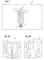
- FIG. 2 is a cut-away side view of the antenna 10 of FIG. 1 .
- the antenna 10 may be used in any of a number of non-harmonic frequency bands. Examples include any (or all) of the frequency bands selected from the group consisting of 750-900 MHz/PCS/UMTS/2.3-2.7 GHz WiFi-WiMAX/3.3-3.8 GHz WiMAX/4.9-6 GHz WiFI.
- the antenna 10 includes a first, low frequency antenna 20 with a primary radiating element 21 extending orthogonally from a ground plane 12 with a proximal end adjacent a ground plane 12 along a longitudinal axis 26 towards a distal end.
- the low frequency antenna 20 is electrically isolated from the ground plane 12 and operates in a low frequency band of a set of non-harmonically related frequency bands.
- the low frequency antenna 20 may include one or more auxiliary low frequency radiating elements 22, 24 coupled to the distal end of the antenna 20. As shown, the low frequency radiating elements 22, 24 extend from the distal end parallel to the ground plane 12. The coupling of the auxiliary radiating elements 22, 24 may be via a directed electrical connection or capacitive coupling.
- a high frequency cone-shaped antenna 14 Formed on the proximal end of the low frequency antenna 20 is a high frequency cone-shaped antenna 14.
- the high frequency antenna 14 operates in a relatively high frequency band of the non-harmonically related frequency bands.
- the low frequency antenna 20 and high frequency antenna 14 are both electrically coupled to a common radio frequency (rf) source through a rf connection (e.g., coaxial cable) 34.
- rf radio frequency
- An apex 30 of the cone-shaped antenna 14 is coincident with and electrically connected to the proximal end of the low frequency antenna 20 at the point where the proximal end of the low frequency antenna 20 is directly adjacent and extends through the ground plane 12.
- a distal end of the cone-shaped antenna 14 opposite the apex 30 i.e., the cone base 32 is coaxial with the longitudinal axis 26 of the low frequency antenna 20.
- the conductive sleeve 16 Disposed around the apex 30 is a first conductive sleeve 16 extending from adjacent the ground plane 12.
- the conductive sleeve 16 includes a sleeve element 42 and a sleeve base 44.
- the conductive sleeve 16 is electrically isolated (in a direct current sense) from both the high frequency antenna 14 and the ground plane 12. However, the conductive sleeve 16 is capacitively coupled 36 to the high frequency antenna 14 and is also capacitively coupled 38 to the ground plane 12.
- the capacitive coupling 36 is determined by a distance 40 between the sleeve element 42 and cone-shaped antenna 14 and the type of dielectric disposed between the sleeve element 42 and cone-shaped antenna 14.
- the capacitive coupling of the second capacitor 38 is determined by a size of the base element 44 and the thickness and type of dielectric 46 disposed between the base element 44 and ground 12.
- a second conductive sleeve 18 Extending away from the base end 32 of the cone-shaped antenna 14 (and from the ground plane 12) is a second conductive sleeve 18.
- a proximal end of the sleeve 18 is adjacent a marginal edge of the cone base 32 and is electrically isolated from the base 32 by a dielectric spacer 28.
- a distal end of the sleeve 18 engages a proximal end of the auxiliary element 22 and is electrically isolated from the auxiliary element 22 by a dielectric spacer 52.
- the low frequency antenna 20 may have a total height of 82 mm including a primary radiating element 21 that is 69 mm high with a pair of secondary radiating elements 22, 24 that extend another 13 mm.
- the diameter of the radiating element 24 is 206 mm.
- the high frequency cone 14 has a height of 26.5 mm along the longitudinal axis 26 and the diameter of the base 32 is 21 mm.
- the first conductive sleeve 16 has a height of 5.8 mm and a diameter of 15 mm.
- the dielectric 46 that supports the antenna 10 above the ground plane 12 is 6003 fiberglass with a 0.02 mm thick mylar tape on the upper surface.
- the second conductive sleeve 18 has a diameter of 21 mm and a height parallel to the predominant axis 26 of 41 mm.
- the dielectric 28 that separates the high frequency antenna 14 and second conductive sleeve 18 is 1.5 mm thick.
- the elements 14, 16, 18, 20 of the antenna 10 may be divided into a number of discrete elements that are continuous in a direction extending away from the ground plane 12, but discrete in a circular direction around the predominant axis 26.
- FIG. 3 is a side perspective view of the antenna 10 (now labeled antenna 100 in FIG. 3 ) where the elements 14, 16, 18, 20 are divided into four discrete elements (e.g., copper traces) extending upwards from the ground plane 12.
- FIGs. 4a-b show side views of two circuit boards 102, 104 that may be used to construct the antenna 100 in conjunction with the circuit board 46.
- the circuit boards 102, 104 each have a slot 106, 108 that allows the circuit boards 102, 104 to be interleaved at substantially right angles.
- the junction between the boards 102, 104 may be joined through use of a solder bridge that electrically joins the copper traces of the primary radiating elements 110 and 112 and the secondary radiating elements 114, 116.
- radiating elements 110 and 112 function as equivalents of the primary radiating element 21 shown in FIGs 1 and 2 and radiating elements 114, 116 function as equivalents of the radiating elements 22, 24.
- the cone shaped high frequency antenna 14 of FIG. 1 and 2 has now been divided up into discrete radiating elements 126, 128, 130, 132.
- sleeve elements 118, 120, 122, 124 now serve substantially the same function as sleeve 18 of FIG. 1 .
- sleeve elements 134, 136, 138, 140 now serve substantially the same function as the sleeve 16 of FIG. 1 .
- a dialectric material 142, 144 separates the sleeve elements 134, 136, 138, 140 from the high frequency antenna 14 of FIG. 3 .
- FIG. 5 provides a VSWR for the antenna 10, 100 over a relatively large set of frequency bands.
- the antenna 10, 100 has a relatively low VSWR in the cellular bands as well as the higher frequency bands.
- the antenna 10, 100 performs well over a broad range of non-harmonically related frequency bands.
- the high frequency cone-shaped antenna 14 operates as a sleeve monopole covering the high band.
- the cone-shaped nature of the high band antenna 14 serves as a broadband choke for high band frequencies essentially preventing high frequency components from propagating upwards past the cone into the low frequency antenna 20.
- the frequency characteristics of the high frequency cone-shaped antenna 14 may be determined by the size of the copper traces 42, 44 on the boards 46, 102, 104. For example, by increasing the size of the copper trace 42 (134, 136, 138, 140 in FIG. 4 ), the capacitive coupling 36 is increased thereby allowing the first sleeve 16 to become a radiator in certain frequency ranges. Similarly, increasing the size of the copper traces 44 increases the capacitive coupling 38 with the ground plane 12, thereby decreasing the radiation capabilities of the first sleeve 16.
- the low frequency antenna 20 is the primary radiator in the lower bands.
- the first sleeve 18 around the low frequency antenna 20 curbs the mid-band frequencies (e.g., at about 1 ⁇ 4 wavelength) and also acts as a low band radiator.
- the low band antenna 20 and choke 18 are not connected.
- the top section (secondary radiators 22, 24) provide loading for proper operation in the low band. Larger secondary radiators 22, 24 would shift the frequency lower. If a LC choke (parallel resonant circuit) with resonate frequency equal to the low band (800 MHz) were to be added onto the top radiator 24 to isolate the low band, then an even lower band (400 MHz or lower) can be realized (e.g., a coil loaded 1/8 wavelength monopole). As another alternative, a UHF hula hoop could be used for an even lower profile combination.
- a multi-band antenna that operates in at least two non-harmonically related frequency bands, such antenna comprising: a cone-shaped antenna element for a relatively high frequency band of the at least two non-harmonically related frequency bands with an apex of the cone-shaped antenna element disposed proximate the ground plane, the cone-shaped antenna element extending along a predominant axis from the apex to a distal base end, the cone-shaped antenna element electrically isolated from the ground plane; a first plurality of secondary antenna elements extending parallel to the predominant axis and arranged in a circle around the cone-shaped antenna element with each of the plurality of secondary antenna elements capacitively coupled to the cone-shaped antenna element and ground plane so as to electrically float between an electrical potential of the cone-shaped antenna element and ground plane; an antenna extension operating at a relatively low frequency band below the high frequency band, the antenna extension electrically coupled to and extending away from the base end and ground plane along the predominant axis; and a second plurality of secondary antenna elements extending away from the base
- a multi-band antenna that operates in at least two non-harmonically related frequency bands, such antenna comprising: cone-shaped high frequency antenna element, the apex of the cone disposed adjacent a ground plane and a base on an opposing end extending away from the ground plane along a longitudinal axis of the cone; a first conductive sleeve of discrete elements extending away from the ground plane parallel to the longitudinal axis that surrounds at least the apex of the cone-shaped antenna element and where the conductive sleeve is electrically isolated from the ground plane and high frequency antenna element; an antenna extension that operates at an intermediate frequency band lower than the high frequency band, the antenna extension electrically coupled to and extending away from the base end and ground plane along the predominant axis; and a second conductive sleeve of discrete elements extending away from the base parallel to the antenna extension and arranged in a circle around the antenna extension and each capacitively coupled to electrically float between an electrical potential of the first sleeve and the antenna extension and where the predominant
Landscapes
- Waveguide Aerials (AREA)
- Details Of Aerials (AREA)
- Variable-Direction Aerials And Aerial Arrays (AREA)
Applications Claiming Priority (1)
| Application Number | Priority Date | Filing Date | Title |
|---|---|---|---|
| US12/187,009 US7999757B2 (en) | 2008-08-06 | 2008-08-06 | Multi-band ceiling antenna |
Publications (2)
| Publication Number | Publication Date |
|---|---|
| EP2154752A1 true EP2154752A1 (de) | 2010-02-17 |
| EP2154752B1 EP2154752B1 (de) | 2016-07-13 |
Family
ID=41101033
Family Applications (1)
| Application Number | Title | Priority Date | Filing Date |
|---|---|---|---|
| EP09166501.8A Not-in-force EP2154752B1 (de) | 2008-08-06 | 2009-07-27 | Mehrband-Deckenantenne |
Country Status (3)
| Country | Link |
|---|---|
| US (1) | US7999757B2 (de) |
| EP (1) | EP2154752B1 (de) |
| CN (1) | CN101645536B (de) |
Cited By (3)
| Publication number | Priority date | Publication date | Assignee | Title |
|---|---|---|---|---|
| DE102011113725A1 (de) * | 2011-09-17 | 2013-03-21 | Volkswagen Aktiengesellschaft | Mehrbereichsantenne für ein Kraftfahrzeug |
| WO2015189471A1 (en) * | 2014-06-09 | 2015-12-17 | Promarine Oy | Conical monopole antenna |
| EP3355409A1 (de) * | 2017-01-27 | 2018-08-01 | Kathrein Werke KG | Breitbandige omnidirektionale antenne |
Families Citing this family (16)
| Publication number | Priority date | Publication date | Assignee | Title |
|---|---|---|---|---|
| US8830131B1 (en) * | 2010-02-17 | 2014-09-09 | Rockwell Collins, Inc. | Dual polarization antenna with high port isolation |
| TW201134007A (en) * | 2010-03-22 | 2011-10-01 | Gemtek Technology Co Ltd | High isolation and multiple-band antenna set incorporated with wireless fidelity antennas and worldwide interoperability for microwave access antennas |
| CN102237575A (zh) * | 2010-04-23 | 2011-11-09 | 正文科技股份有限公司 | 结合无线兼容认证天线及全球微波互联接入天线的天线组 |
| US9899733B1 (en) * | 2011-05-23 | 2018-02-20 | R.A. Miller Industries, Inc. | Multiband blade antenna |
| US8957822B2 (en) * | 2012-09-13 | 2015-02-17 | ImagineCommunications Corp. | Operation of an antenna on a second, higher frequency |
| US9577329B2 (en) * | 2012-12-28 | 2017-02-21 | Galtronics Corporation, Ltd. | Ultra-broadband antenna with capacitively coupled ground leg |
| US9595755B2 (en) | 2013-10-04 | 2017-03-14 | Laird Technologies, Inc. | Ground independent multi-band antenna assemblies |
| WO2015069309A1 (en) * | 2013-11-07 | 2015-05-14 | Laird Technologies, Inc. | Omnidirectional broadband antennas |
| US20160043472A1 (en) * | 2014-04-28 | 2016-02-11 | Tyco Electronics Corporation | Monocone antenna |
| US9692136B2 (en) * | 2014-04-28 | 2017-06-27 | Te Connectivity Corporation | Monocone antenna |
| CN104183907B (zh) * | 2014-08-25 | 2016-09-28 | 广东晖速通信技术有限公司 | 一种低频振子 |
| CN104901024B (zh) * | 2015-03-25 | 2017-11-07 | 康凯科技(杭州)股份有限公司 | 应用于wifi中的多模式锥形天线系统 |
| US9680215B2 (en) * | 2015-07-21 | 2017-06-13 | Laird Technologies, Inc. | Omnidirectional broadband antennas including capacitively grounded cable brackets |
| CN106129599B (zh) * | 2016-08-23 | 2020-10-16 | 佛山市三水区冠华通讯设备厂 | 一种新型辐射振子及由其组成的吸顶天线 |
| CN106941211A (zh) * | 2017-02-24 | 2017-07-11 | Pc-Tel公司 | 多馈电天线辐射单元、mimo多天线系统及其制作方法 |
| US10498047B1 (en) * | 2017-09-20 | 2019-12-03 | Pc-Tel, Inc. | Capacitively-coupled dual-band antenna |
Citations (7)
| Publication number | Priority date | Publication date | Assignee | Title |
|---|---|---|---|---|
| US4635068A (en) | 1985-06-05 | 1987-01-06 | Hazeltine Corporation | Double-tuned disc loaded monopole |
| GB2327813A (en) * | 1997-07-31 | 1999-02-03 | Northern Telecom Ltd | A dual resonant antenna |
| EP1033782A2 (de) * | 1999-03-02 | 2000-09-06 | Matsushita Electric Industrial Co., Ltd. | Monopolantenne |
| US20050134516A1 (en) | 2003-12-17 | 2005-06-23 | Andrew Corporation | Dual Band Sleeve Antenna |
| US20050134511A1 (en) * | 2003-12-18 | 2005-06-23 | Kathrein-Werke Kg | Broadband Omnidirectional Antenna |
| US20070085743A1 (en) | 2005-10-18 | 2007-04-19 | Paul Eberhardt | Antenna system and apparatus |
| US20070247382A1 (en) | 2006-04-25 | 2007-10-25 | Joymax Electronics Co., Ltd. | Antenna having wide transmitting angle |
Family Cites Families (13)
| Publication number | Priority date | Publication date | Assignee | Title |
|---|---|---|---|---|
| GB691485A (en) * | 1950-08-04 | 1953-05-13 | Michael Dominic Ercolino | High frequency antennas |
| DE2629502A1 (de) * | 1976-06-30 | 1978-01-05 | Siemens Ag | Mehrfachrundstrahlantenne |
| US6369766B1 (en) * | 1999-12-14 | 2002-04-09 | Ems Technologies, Inc. | Omnidirectional antenna utilizing an asymmetrical bicone as a passive feed for a radiating element |
| CN2558099Y (zh) * | 2002-05-01 | 2003-06-25 | 中山市通宇通讯设备有限公司 | 吸顶天线 |
| US7283101B2 (en) * | 2003-06-26 | 2007-10-16 | Andrew Corporation | Antenna element, feed probe; dielectric spacer, antenna and method of communicating with a plurality of devices |
| CN2746565Y (zh) * | 2004-08-11 | 2005-12-14 | 陈晖� | 双宽频侧定向吸顶天线 |
| US7242352B2 (en) * | 2005-04-07 | 2007-07-10 | X-Ether, Inc, | Multi-band or wide-band antenna |
| DE102005054286B4 (de) * | 2005-11-11 | 2011-04-07 | Delphi Delco Electronics Europe Gmbh | Antennenanordnung |
| TWM290615U (en) * | 2005-11-18 | 2006-05-11 | Smart Ant Telecom Co Ltd | Structure of antenna |
| CN2877057Y (zh) * | 2006-03-14 | 2007-03-07 | 京信通信技术(广州)有限公司 | 宽频全向吸顶天线 |
| CN1917286B (zh) * | 2006-09-01 | 2011-09-28 | 京信通信技术(广州)有限公司 | 吸顶式宽频定向辐射天线 |
| TWI340503B (en) * | 2007-09-07 | 2011-04-11 | Quanta Comp Inc | Antenna module |
| CN201142360Y (zh) * | 2007-12-04 | 2008-10-29 | 东莞市晖速天线技术有限公司 | 天线 |
-
2008
- 2008-08-06 US US12/187,009 patent/US7999757B2/en active Active
-
2009
- 2009-07-27 EP EP09166501.8A patent/EP2154752B1/de not_active Not-in-force
- 2009-08-06 CN CN200910165605.5A patent/CN101645536B/zh not_active Expired - Fee Related
Patent Citations (7)
| Publication number | Priority date | Publication date | Assignee | Title |
|---|---|---|---|---|
| US4635068A (en) | 1985-06-05 | 1987-01-06 | Hazeltine Corporation | Double-tuned disc loaded monopole |
| GB2327813A (en) * | 1997-07-31 | 1999-02-03 | Northern Telecom Ltd | A dual resonant antenna |
| EP1033782A2 (de) * | 1999-03-02 | 2000-09-06 | Matsushita Electric Industrial Co., Ltd. | Monopolantenne |
| US20050134516A1 (en) | 2003-12-17 | 2005-06-23 | Andrew Corporation | Dual Band Sleeve Antenna |
| US20050134511A1 (en) * | 2003-12-18 | 2005-06-23 | Kathrein-Werke Kg | Broadband Omnidirectional Antenna |
| US20070085743A1 (en) | 2005-10-18 | 2007-04-19 | Paul Eberhardt | Antenna system and apparatus |
| US20070247382A1 (en) | 2006-04-25 | 2007-10-25 | Joymax Electronics Co., Ltd. | Antenna having wide transmitting angle |
Cited By (5)
| Publication number | Priority date | Publication date | Assignee | Title |
|---|---|---|---|---|
| DE102011113725A1 (de) * | 2011-09-17 | 2013-03-21 | Volkswagen Aktiengesellschaft | Mehrbereichsantenne für ein Kraftfahrzeug |
| WO2015189471A1 (en) * | 2014-06-09 | 2015-12-17 | Promarine Oy | Conical monopole antenna |
| EP3355409A1 (de) * | 2017-01-27 | 2018-08-01 | Kathrein Werke KG | Breitbandige omnidirektionale antenne |
| US20180219282A1 (en) * | 2017-01-27 | 2018-08-02 | Kathrein-Werke Kg | Broadband omnidirectional antenna |
| US10461415B2 (en) * | 2017-01-27 | 2019-10-29 | Kathrein Se | Broadband omnidirectional antenna |
Also Published As
| Publication number | Publication date |
|---|---|
| CN101645536B (zh) | 2014-09-17 |
| EP2154752B1 (de) | 2016-07-13 |
| CN101645536A (zh) | 2010-02-10 |
| US7999757B2 (en) | 2011-08-16 |
| US20100033401A1 (en) | 2010-02-11 |
Similar Documents
| Publication | Publication Date | Title |
|---|---|---|
| US7999757B2 (en) | Multi-band ceiling antenna | |
| US10784578B2 (en) | Antenna system | |
| US8184060B2 (en) | Low profile antenna | |
| US9786980B2 (en) | Antenna system | |
| US6734825B1 (en) | Miniature built-in multiple frequency band antenna | |
| US8259014B2 (en) | Multi-loop antenna structure and hand-held electronic device using the same | |
| US8711043B2 (en) | Wideband antenna | |
| US20170207542A1 (en) | Antenna structure | |
| US8456366B2 (en) | Communications structures including antennas with separate antenna branches coupled to feed and ground conductors | |
| US8922449B2 (en) | Communication electronic device and antenna structure thereof | |
| US10084240B2 (en) | Wideband wide beamwidth MIMO antenna system | |
| CN104396086A (zh) | 一种天线及移动终端 | |
| US8115695B2 (en) | Print dipole antenna and manufacturing method thereof | |
| US7170456B2 (en) | Dielectric chip antenna structure | |
| JP2012518300A (ja) | アンテナ構成、プリント回路基板、携帯電子機器、及び変換キット | |
| CN103151601A (zh) | 一种底边槽耦合天线 | |
| US10374311B2 (en) | Antenna for a portable communication device | |
| US8063847B2 (en) | Multi-band antenna | |
| US20110156971A1 (en) | Wide band antenna | |
| US7193566B2 (en) | Planar monopole antennas | |
| JP2010087752A (ja) | マルチバンドアンテナ | |
| US8035566B2 (en) | Multi-band antenna | |
| US9054426B2 (en) | Radio apparatus and antenna device | |
| US8754821B2 (en) | Multi-band antenna | |
| JPH09232854A (ja) | 移動無線機用小型平面アンテナ装置 |
Legal Events
| Date | Code | Title | Description |
|---|---|---|---|
| PUAI | Public reference made under article 153(3) epc to a published international application that has entered the european phase |
Free format text: ORIGINAL CODE: 0009012 |
|
| AK | Designated contracting states |
Kind code of ref document: A1 Designated state(s): AT BE BG CH CY CZ DE DK EE ES FI FR GB GR HR HU IE IS IT LI LT LU LV MC MK MT NL NO PL PT RO SE SI SK SM TR |
|
| AX | Request for extension of the european patent |
Extension state: AL BA RS |
|
| 17P | Request for examination filed |
Effective date: 20100817 |
|
| 17Q | First examination report despatched |
Effective date: 20100914 |
|
| REG | Reference to a national code |
Ref country code: DE Ref legal event code: R079 Ref document number: 602009039676 Country of ref document: DE Free format text: PREVIOUS MAIN CLASS: H01Q0009360000 Ipc: H01Q0001000000 |
|
| GRAP | Despatch of communication of intention to grant a patent |
Free format text: ORIGINAL CODE: EPIDOSNIGR1 |
|
| RIC1 | Information provided on ipc code assigned before grant |
Ipc: H01Q 19/32 20060101ALI20160112BHEP Ipc: H01Q 1/00 20060101AFI20160112BHEP Ipc: H01Q 21/30 20060101ALI20160112BHEP Ipc: H01Q 9/36 20060101ALI20160112BHEP |
|
| INTG | Intention to grant announced |
Effective date: 20160203 |
|
| GRAS | Grant fee paid |
Free format text: ORIGINAL CODE: EPIDOSNIGR3 |
|
| GRAA | (expected) grant |
Free format text: ORIGINAL CODE: 0009210 |
|
| AK | Designated contracting states |
Kind code of ref document: B1 Designated state(s): AT BE BG CH CY CZ DE DK EE ES FI FR GB GR HR HU IE IS IT LI LT LU LV MC MK MT NL NO PL PT RO SE SI SK SM TR |
|
| REG | Reference to a national code |
Ref country code: GB Ref legal event code: FG4D |
|
| REG | Reference to a national code |
Ref country code: AT Ref legal event code: REF Ref document number: 812963 Country of ref document: AT Kind code of ref document: T Effective date: 20160715 Ref country code: CH Ref legal event code: EP |
|
| REG | Reference to a national code |
Ref country code: IE Ref legal event code: FG4D |
|
| REG | Reference to a national code |
Ref country code: DE Ref legal event code: R096 Ref document number: 602009039676 Country of ref document: DE |
|
| REG | Reference to a national code |
Ref country code: FR Ref legal event code: PLFP Year of fee payment: 8 |
|
| REG | Reference to a national code |
Ref country code: LT Ref legal event code: MG4D |
|
| REG | Reference to a national code |
Ref country code: NL Ref legal event code: MP Effective date: 20160713 |
|
| REG | Reference to a national code |
Ref country code: AT Ref legal event code: MK05 Ref document number: 812963 Country of ref document: AT Kind code of ref document: T Effective date: 20160713 |
|
| PG25 | Lapsed in a contracting state [announced via postgrant information from national office to epo] |
Ref country code: BE Free format text: LAPSE BECAUSE OF NON-PAYMENT OF DUE FEES Effective date: 20160731 |
|
| PG25 | Lapsed in a contracting state [announced via postgrant information from national office to epo] |
Ref country code: HR Free format text: LAPSE BECAUSE OF FAILURE TO SUBMIT A TRANSLATION OF THE DESCRIPTION OR TO PAY THE FEE WITHIN THE PRESCRIBED TIME-LIMIT Effective date: 20160713 Ref country code: LT Free format text: LAPSE BECAUSE OF FAILURE TO SUBMIT A TRANSLATION OF THE DESCRIPTION OR TO PAY THE FEE WITHIN THE PRESCRIBED TIME-LIMIT Effective date: 20160713 Ref country code: IS Free format text: LAPSE BECAUSE OF FAILURE TO SUBMIT A TRANSLATION OF THE DESCRIPTION OR TO PAY THE FEE WITHIN THE PRESCRIBED TIME-LIMIT Effective date: 20161113 Ref country code: IT Free format text: LAPSE BECAUSE OF FAILURE TO SUBMIT A TRANSLATION OF THE DESCRIPTION OR TO PAY THE FEE WITHIN THE PRESCRIBED TIME-LIMIT Effective date: 20160713 Ref country code: NL Free format text: LAPSE BECAUSE OF FAILURE TO SUBMIT A TRANSLATION OF THE DESCRIPTION OR TO PAY THE FEE WITHIN THE PRESCRIBED TIME-LIMIT Effective date: 20160713 Ref country code: FI Free format text: LAPSE BECAUSE OF FAILURE TO SUBMIT A TRANSLATION OF THE DESCRIPTION OR TO PAY THE FEE WITHIN THE PRESCRIBED TIME-LIMIT Effective date: 20160713 Ref country code: NO Free format text: LAPSE BECAUSE OF FAILURE TO SUBMIT A TRANSLATION OF THE DESCRIPTION OR TO PAY THE FEE WITHIN THE PRESCRIBED TIME-LIMIT Effective date: 20161013 |
|
| PG25 | Lapsed in a contracting state [announced via postgrant information from national office to epo] |
Ref country code: PT Free format text: LAPSE BECAUSE OF FAILURE TO SUBMIT A TRANSLATION OF THE DESCRIPTION OR TO PAY THE FEE WITHIN THE PRESCRIBED TIME-LIMIT Effective date: 20161114 Ref country code: PL Free format text: LAPSE BECAUSE OF FAILURE TO SUBMIT A TRANSLATION OF THE DESCRIPTION OR TO PAY THE FEE WITHIN THE PRESCRIBED TIME-LIMIT Effective date: 20160713 Ref country code: GR Free format text: LAPSE BECAUSE OF FAILURE TO SUBMIT A TRANSLATION OF THE DESCRIPTION OR TO PAY THE FEE WITHIN THE PRESCRIBED TIME-LIMIT Effective date: 20161014 Ref country code: BE Free format text: LAPSE BECAUSE OF FAILURE TO SUBMIT A TRANSLATION OF THE DESCRIPTION OR TO PAY THE FEE WITHIN THE PRESCRIBED TIME-LIMIT Effective date: 20160713 Ref country code: LV Free format text: LAPSE BECAUSE OF FAILURE TO SUBMIT A TRANSLATION OF THE DESCRIPTION OR TO PAY THE FEE WITHIN THE PRESCRIBED TIME-LIMIT Effective date: 20160713 Ref country code: SE Free format text: LAPSE BECAUSE OF FAILURE TO SUBMIT A TRANSLATION OF THE DESCRIPTION OR TO PAY THE FEE WITHIN THE PRESCRIBED TIME-LIMIT Effective date: 20160713 Ref country code: ES Free format text: LAPSE BECAUSE OF FAILURE TO SUBMIT A TRANSLATION OF THE DESCRIPTION OR TO PAY THE FEE WITHIN THE PRESCRIBED TIME-LIMIT Effective date: 20160713 Ref country code: AT Free format text: LAPSE BECAUSE OF FAILURE TO SUBMIT A TRANSLATION OF THE DESCRIPTION OR TO PAY THE FEE WITHIN THE PRESCRIBED TIME-LIMIT Effective date: 20160713 |
|
| REG | Reference to a national code |
Ref country code: CH Ref legal event code: PL |
|
| REG | Reference to a national code |
Ref country code: DE Ref legal event code: R097 Ref document number: 602009039676 Country of ref document: DE |
|
| PG25 | Lapsed in a contracting state [announced via postgrant information from national office to epo] |
Ref country code: LI Free format text: LAPSE BECAUSE OF NON-PAYMENT OF DUE FEES Effective date: 20160731 Ref country code: EE Free format text: LAPSE BECAUSE OF FAILURE TO SUBMIT A TRANSLATION OF THE DESCRIPTION OR TO PAY THE FEE WITHIN THE PRESCRIBED TIME-LIMIT Effective date: 20160713 Ref country code: RO Free format text: LAPSE BECAUSE OF FAILURE TO SUBMIT A TRANSLATION OF THE DESCRIPTION OR TO PAY THE FEE WITHIN THE PRESCRIBED TIME-LIMIT Effective date: 20160713 Ref country code: MC Free format text: LAPSE BECAUSE OF FAILURE TO SUBMIT A TRANSLATION OF THE DESCRIPTION OR TO PAY THE FEE WITHIN THE PRESCRIBED TIME-LIMIT Effective date: 20160713 Ref country code: CH Free format text: LAPSE BECAUSE OF NON-PAYMENT OF DUE FEES Effective date: 20160731 |
|
| REG | Reference to a national code |
Ref country code: IE Ref legal event code: MM4A |
|
| PLBE | No opposition filed within time limit |
Free format text: ORIGINAL CODE: 0009261 |
|
| STAA | Information on the status of an ep patent application or granted ep patent |
Free format text: STATUS: NO OPPOSITION FILED WITHIN TIME LIMIT |
|
| PG25 | Lapsed in a contracting state [announced via postgrant information from national office to epo] |
Ref country code: BG Free format text: LAPSE BECAUSE OF FAILURE TO SUBMIT A TRANSLATION OF THE DESCRIPTION OR TO PAY THE FEE WITHIN THE PRESCRIBED TIME-LIMIT Effective date: 20161013 Ref country code: SM Free format text: LAPSE BECAUSE OF FAILURE TO SUBMIT A TRANSLATION OF THE DESCRIPTION OR TO PAY THE FEE WITHIN THE PRESCRIBED TIME-LIMIT Effective date: 20160713 Ref country code: CZ Free format text: LAPSE BECAUSE OF FAILURE TO SUBMIT A TRANSLATION OF THE DESCRIPTION OR TO PAY THE FEE WITHIN THE PRESCRIBED TIME-LIMIT Effective date: 20160713 Ref country code: SK Free format text: LAPSE BECAUSE OF FAILURE TO SUBMIT A TRANSLATION OF THE DESCRIPTION OR TO PAY THE FEE WITHIN THE PRESCRIBED TIME-LIMIT Effective date: 20160713 Ref country code: DK Free format text: LAPSE BECAUSE OF FAILURE TO SUBMIT A TRANSLATION OF THE DESCRIPTION OR TO PAY THE FEE WITHIN THE PRESCRIBED TIME-LIMIT Effective date: 20160713 |
|
| 26N | No opposition filed |
Effective date: 20170418 |
|
| REG | Reference to a national code |
Ref country code: FR Ref legal event code: PLFP Year of fee payment: 9 |
|
| PG25 | Lapsed in a contracting state [announced via postgrant information from national office to epo] |
Ref country code: IE Free format text: LAPSE BECAUSE OF NON-PAYMENT OF DUE FEES Effective date: 20160727 |
|
| PGFP | Annual fee paid to national office [announced via postgrant information from national office to epo] |
Ref country code: FR Payment date: 20170621 Year of fee payment: 9 Ref country code: GB Payment date: 20170626 Year of fee payment: 9 |
|
| PG25 | Lapsed in a contracting state [announced via postgrant information from national office to epo] |
Ref country code: LU Free format text: LAPSE BECAUSE OF NON-PAYMENT OF DUE FEES Effective date: 20160727 Ref country code: SI Free format text: LAPSE BECAUSE OF FAILURE TO SUBMIT A TRANSLATION OF THE DESCRIPTION OR TO PAY THE FEE WITHIN THE PRESCRIBED TIME-LIMIT Effective date: 20160713 |
|
| PGFP | Annual fee paid to national office [announced via postgrant information from national office to epo] |
Ref country code: DE Payment date: 20170726 Year of fee payment: 9 |
|
| PG25 | Lapsed in a contracting state [announced via postgrant information from national office to epo] |
Ref country code: HU Free format text: LAPSE BECAUSE OF FAILURE TO SUBMIT A TRANSLATION OF THE DESCRIPTION OR TO PAY THE FEE WITHIN THE PRESCRIBED TIME-LIMIT; INVALID AB INITIO Effective date: 20090727 Ref country code: CY Free format text: LAPSE BECAUSE OF FAILURE TO SUBMIT A TRANSLATION OF THE DESCRIPTION OR TO PAY THE FEE WITHIN THE PRESCRIBED TIME-LIMIT Effective date: 20160713 |
|
| PG25 | Lapsed in a contracting state [announced via postgrant information from national office to epo] |
Ref country code: MT Free format text: LAPSE BECAUSE OF NON-PAYMENT OF DUE FEES Effective date: 20160731 Ref country code: MK Free format text: LAPSE BECAUSE OF FAILURE TO SUBMIT A TRANSLATION OF THE DESCRIPTION OR TO PAY THE FEE WITHIN THE PRESCRIBED TIME-LIMIT Effective date: 20160713 Ref country code: TR Free format text: LAPSE BECAUSE OF FAILURE TO SUBMIT A TRANSLATION OF THE DESCRIPTION OR TO PAY THE FEE WITHIN THE PRESCRIBED TIME-LIMIT Effective date: 20160713 |
|
| REG | Reference to a national code |
Ref country code: DE Ref legal event code: R119 Ref document number: 602009039676 Country of ref document: DE |
|
| GBPC | Gb: european patent ceased through non-payment of renewal fee |
Effective date: 20180727 |
|
| PG25 | Lapsed in a contracting state [announced via postgrant information from national office to epo] |
Ref country code: DE Free format text: LAPSE BECAUSE OF NON-PAYMENT OF DUE FEES Effective date: 20190201 Ref country code: FR Free format text: LAPSE BECAUSE OF NON-PAYMENT OF DUE FEES Effective date: 20180731 Ref country code: GB Free format text: LAPSE BECAUSE OF NON-PAYMENT OF DUE FEES Effective date: 20180727 |