EP2154752B1 - Mehrband-Deckenantenne - Google Patents
Mehrband-Deckenantenne Download PDFInfo
- Publication number
- EP2154752B1 EP2154752B1 EP09166501.8A EP09166501A EP2154752B1 EP 2154752 B1 EP2154752 B1 EP 2154752B1 EP 09166501 A EP09166501 A EP 09166501A EP 2154752 B1 EP2154752 B1 EP 2154752B1
- Authority
- EP
- European Patent Office
- Prior art keywords
- antenna
- high frequency
- ground plane
- sleeve
- low frequency
- Prior art date
- Legal status (The legal status is an assumption and is not a legal conclusion. Google has not performed a legal analysis and makes no representation as to the accuracy of the status listed.)
- Not-in-force
Links
- MPTQRFCYZCXJFQ-UHFFFAOYSA-L copper(II) chloride dihydrate Chemical compound O.O.[Cl-].[Cl-].[Cu+2] MPTQRFCYZCXJFQ-UHFFFAOYSA-L 0.000 claims description 9
- 230000008878 coupling Effects 0.000 claims description 8
- 238000010168 coupling process Methods 0.000 claims description 8
- 238000005859 coupling reaction Methods 0.000 claims description 8
- 125000006850 spacer group Chemical group 0.000 claims description 5
- 230000005855 radiation Effects 0.000 claims description 2
- 230000007423 decrease Effects 0.000 claims 1
- 230000001413 cellular effect Effects 0.000 description 6
- 230000005404 monopole Effects 0.000 description 5
- RYGMFSIKBFXOCR-UHFFFAOYSA-N Copper Chemical compound [Cu] RYGMFSIKBFXOCR-UHFFFAOYSA-N 0.000 description 4
- 229910052802 copper Inorganic materials 0.000 description 4
- 239000010949 copper Substances 0.000 description 4
- 229920002799 BoPET Polymers 0.000 description 1
- 239000003990 capacitor Substances 0.000 description 1
- 230000003247 decreasing effect Effects 0.000 description 1
- 239000003989 dielectric material Substances 0.000 description 1
- 239000011152 fibreglass Substances 0.000 description 1
- 230000001902 propagating effect Effects 0.000 description 1
- 229910000679 solder Inorganic materials 0.000 description 1
Images


Classifications
-
- H—ELECTRICITY
- H01—ELECTRIC ELEMENTS
- H01Q—ANTENNAS, i.e. RADIO AERIALS
- H01Q1/00—Details of, or arrangements associated with, antennas
- H01Q1/007—Details of, or arrangements associated with, antennas specially adapted for indoor communication
-
- H—ELECTRICITY
- H01—ELECTRIC ELEMENTS
- H01Q—ANTENNAS, i.e. RADIO AERIALS
- H01Q19/00—Combinations of primary active antenna elements and units with secondary devices, e.g. with quasi-optical devices, for giving the antenna a desired directional characteristic
- H01Q19/28—Combinations of primary active antenna elements and units with secondary devices, e.g. with quasi-optical devices, for giving the antenna a desired directional characteristic using a secondary device in the form of two or more substantially straight conductive elements
- H01Q19/32—Combinations of primary active antenna elements and units with secondary devices, e.g. with quasi-optical devices, for giving the antenna a desired directional characteristic using a secondary device in the form of two or more substantially straight conductive elements the primary active element being end-fed and elongated
-
- H—ELECTRICITY
- H01—ELECTRIC ELEMENTS
- H01Q—ANTENNAS, i.e. RADIO AERIALS
- H01Q21/00—Antenna arrays or systems
- H01Q21/30—Combinations of separate antenna units operating in different wavebands and connected to a common feeder system
-
- H—ELECTRICITY
- H01—ELECTRIC ELEMENTS
- H01Q—ANTENNAS, i.e. RADIO AERIALS
- H01Q9/00—Electrically-short antennas having dimensions not more than twice the operating wavelength and consisting of conductive active radiating elements
- H01Q9/04—Resonant antennas
- H01Q9/30—Resonant antennas with feed to end of elongated active element, e.g. unipole
- H01Q9/32—Vertical arrangement of element
- H01Q9/36—Vertical arrangement of element with top loading
Definitions
- the field of the invention relates to radio frequency antenna and more particularly to antenna that operate in a number of different non-harmonically related frequencies.
- Digital wireless systems such as wireless local area networks, or cellular devices, such as cellular telephones may exist in a number of different frequency bands and may each use a unique communication protocol.
- cellular and GSM telephones may operate in the 750-960 MHz frequency band
- PCS and UMTS may operate in a 1700-2170 MHz frequency band
- WIFI may operate in the 2.4-5.8 GHz bands.
- cellular, PCS, UMTS, and WIFI are often used with different types of devices, each with a different functionality and data processing capability. Because of the different functionality, it is often necessary for service providers to provide simultaneous infrastructure access under each of the different protocols.
- the patch may be conventional or include one or more slots for high frequency operation.
- the monopole antenna While, the use of the monopole and patch antenna is effective in some cases, the monopole antenna often experiences a phase reversal at high frequencies resulting in an elevation pattern split of a radiated signal. In addition where the patch antenna structure exceeds 1 ⁇ 4 wavelength in high band frequencies, the radiated field has significant azimuth pattern distortion. Accordingly, a need exist for better antenna that operate in multiple non-harmonically related frequency bands.
- US 2007/0247382 and GB2327813 disclose an antenna having a longitudinal antenna member that operates at lower frequencies and a cylindrical antenna member that operates at higher frequencies.
- US 2007/0085743 discloses broadband antennas that are fabricated on printed circuit boards.
- US 2005/0134516 discloses an antenna having a sleeve that is concentric about an antenna element.
- US 4,635,068 discloses an antenna in which a metallic strip, that is concentric about a dielectric support and a central post, is provided.
- US 2005/0134516 requires varying the length and diameter of both the antenna element and the sleeve to tune the response of the antenna.
- a multi-band antenna that operates in at least two non-harmonically related frequency bands according to claim 1, such antenna comprising inter alia:
- a multi-band antenna that operates in at least two non-harmonically related frequency bands, such antenna comprising inter alia:
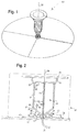
- FIG. 1 depicts an ultra-wide band antenna 10 shown generally in accordance with an illustrated embodiment of the invention.
- FIG. 2 is a cut-away side view of the antenna 10 of FIG. 1 .
- the antenna 10 may be used in any of a number of non-harmonic frequency bands. Examples include any (or all) of the frequency bands selected from the group consisting of 750-900 MHz/PCS/UMTS/2.3-2.7 GHz WiFi-WiMAX/3.3-3.8 GHz WiMAX/4.9-6 GHz WiFI.
- the antenna 10 includes a first, low frequency antenna 20 with a primary radiating element 21 extending orthogonally from a ground plane 12 with a proximal end adjacent a ground plane 12 along a longitudinal axis 26 towards a distal end.
- the low frequency antenna 20 is electrically isolated from the ground plane 12 and operates in a low frequency band of a set of non-harmonically related frequency bands.
- the low frequency antenna 20 may include one or more auxiliary low frequency radiating elements 22, 24 coupled to the distal end of the antenna 20. As shown, the low frequency radiating elements 22, 24 extend from the distal end parallel to the ground plane 12. The coupling of the auxiliary radiating elements 22, 24 may be via a directed electrical connection or capacitive coupling.
- a high frequency cone-shaped antenna 14 Formed on the proximal end of the low frequency antenna 20 is a high frequency cone-shaped antenna 14.
- the high frequency antenna 14 operates in a relatively high frequency band of the non-harmonically related frequency bands.
- the low frequency antenna 20 and high frequency antenna 14 are both electrically coupled to a common radio frequency (rf) source through a rf connection (e.g., coaxial cable) 34.
- rf radio frequency
- An apex 30 of the cone-shaped antenna 14 is coincident with and electrically connected to the proximal end of the low frequency antenna 20 at the point where the proximal end of the low frequency antenna 20 is directly adjacent and extends through the ground plane 12.
- a distal end of the cone-shaped antenna 14 opposite the apex 30 i.e., the cone base 32 is coaxial with the longitudinal axis 26 of the low frequency antenna 20.
- the conductive sleeve 16 Disposed around the apex 30 is a first conductive sleeve 16 extending from adjacent the ground plane 12.
- the conductive sleeve 16 includes a sleeve element 42 and a sleeve base 44.
- the conductive sleeve 16 is electrically isolated (in a direct current sense) from both the high frequency antenna 14 and the ground plane 12. However, the conductive sleeve 16 is capacitively coupled 36 to the high frequency antenna 14 and is also capacitively coupled 38 to the ground plane 12.
- the capacitive coupling 36 is determined by a distance 40 between the sleeve element 42 and cone-shaped antenna 14 and the type of dielectric disposed between the sleeve element 42 and cone-shaped antenna 14.
- the capacitive coupling of the second capacitor 38 is determined by a size of the base element 44 and the thickness and type of dielectric 46 disposed between the base element 44 and ground 12.
- a second conductive sleeve 18 Extending away from the base end 32 of the cone-shaped antenna 14 (and from the ground plane 12) is a second conductive sleeve 18.
- a proximal end of the sleeve 18 is adjacent a marginal edge of the cone base 32 and is electrically isolated from the base 32 by a dielectric spacer 28.
- a distal end of the sleeve 18 engages a proximal end of the auxiliary element 22 and is electrically isolated from the auxiliary element 22 by a dielectric spacer 52.
- the low frequency antenna 20 may have a total height of 82 mm including a primary radiating element 21 that is 69 mm high with a pair of secondary radiating elements 22, 24 that extend another 13 mm.
- the diameter of the radiating element 24 is 206 mm.
- the high frequency cone 14 has a height of 26.5 mm along the longitudinal axis 26 and the diameter of the base 32 is 21 mm.
- the first conductive sleeve 16 has a height of 5.8 mm and a diameter of 15 mm.
- the dielectric 46 that supports the antenna 10 above the ground plane 12 is 6003 fiberglass with a 0.02 mm thick mylar tape on the upper surface.
- the second conductive sleeve 18 has a diameter of 21 mm and a height parallel to the predominant axis 26 of 41 mm.
- the dielectric 28 that separates the high frequency antenna 14 and second conductive sleeve 18 is 1.5 mm thick.
- the elements 14, 16, 18, 20 of the antenna 10 may be divided into a number of discrete elements that are continuous in a direction extending away from the ground plane 12, but discrete in a circular direction around the predominant axis 26.
- FIG. 3 is a side perspective view of the antenna 10 (now labeled antenna 100 in FIG. 3 ) where the elements 14, 16, 18, 20 are divided into four discrete elements (e.g., copper traces) extending upwards from the ground plane 12.
- FIGs. 4a-b show side views of two circuit boards 102, 104 that may be used to construct the antenna 100 in conjunction with the circuit board 46.
- the circuit boards 102, 104 each have a slot 106, 108 that allows the circuit boards 102, 104 to be interleaved at substantially right angles.
- the junction between the boards 102, 104 may be joined through use of a solder bridge that electrically joins the copper traces of the primary radiating elements 110 and 112 and the secondary radiating elements 114, 116.
- radiating elements 110 and 112 function as equivalents of the primary radiating element 21 shown in FIGs 1 and 2 and radiating elements 114, 116 function as equivalents of the radiating elements 22, 24.
- the cone shaped high frequency antenna 14 of FIG. 1 and 2 has now been divided up into discrete radiating elements 126, 128, 130, 132.
- sleeve elements 118, 120, 122, 124 now serve substantially the same function as sleeve 18 of FIG. 1 .
- sleeve elements 134, 136, 138, 140 now serve substantially the same function as the sleeve 16 of FIG. 1 .
- a dielectric material 142, 144 separates the sleeve elements 134, 136, 138, 140 from the high frequency antenna 14 of FIG. 3 .
- FIG. 5 provides a VSWR for the antenna 10, 100 over a relatively large set of frequency bands.
- the antenna 10, 100 has a relatively low VSWR in the cellular bands as well as the higher frequency bands.
- the antenna 10, 100 performs well over a broad range of non-harmonically related frequency bands.
- the high frequency cone-shaped antenna 14 operates as a sleeve monopole covering the high band.
- the cone-shaped nature of the high band antenna 14 serves as a broadband choke for high band frequencies essentially preventing high frequency components from propagating upwards past the cone into the low frequency antenna 20.
- the frequency characteristics of the high frequency cone-shaped antenna 14 may be determined by the size of the copper traces 42, 44 on the boards 46, 102, 104. For example, by increasing the size of the copper trace 42 (134, 136, 138, 140 in FIG. 4 ), the capacitive coupling 36 is increased thereby allowing the first sleeve 16 to become a radiator in certain frequency ranges. Similarly, increasing the size of the copper traces 44 increases the capacitive coupling 38 with the ground plane 12, thereby decreasing the radiation capabilities of the first sleeve 16.
- the low frequency antenna 20 is the primary radiator in the lower bands.
- the first sleeve 18 around the low frequency antenna 20 curbs the mid-band frequencies (e.g., at about 1 ⁇ 4 wavelength) and also acts as a low band radiator.
- the low band antenna 20 and choke 18 are not connected.
- the top section (secondary radiators 22, 24) provide loading for proper operation in the low band. Larger secondary radiators 22, 24 would shift the frequency lower. If a LC choke (parallel resonant circuit) with resonate frequency equal to the low band (800 MHz) were to be added onto the top radiator 24 to isolate the low band, then an even lower band (400 MHz or lower) can be realized (e.g., a coil loaded 1/8 wavelength monopole). As another alternative, a UHF hula hoop could be used for an even lower profile combination.
Landscapes
- Waveguide Aerials (AREA)
- Details Of Aerials (AREA)
- Variable-Direction Aerials And Aerial Arrays (AREA)
Claims (10)
- Multibandantenne (10), die in mindestens zwei zueinander nicht harmonischen Frequenzbändern arbeitet, wobei die Antenne Folgendes umfasst:eine lineare Niedrigfrequenzantenne (20) für ein relativ niedriges Frequenzband der mindestens zwei zueinander nicht harmonischen Frequenzbänder, wobei sich die Niedrigfrequenzantenne (20) an einem nahen Ende rechtwinklig von einer Bodenebene (12) aus entlang einer Hauptachse (26) erstreckt und von der Bodenebene (12) elektrisch isoliert ist,eine Antenne (14) für relativ hohe Frequenzen für ein Band mit relativ hoher Frequenz der mindestens zwei zueinander nicht harmonischen Frequenzbänder, wobei die Antenne (14) für relativ hohe Frequenzen an einem nahen Ende der Niedrigfrequenzantenne (20) angeordnet und elektrisch mit diesem verbunden ist, wobei ein Scheitelpunkt (30) der Antenne (14) für relativ hohe Frequenzen angrenzend an die Bodenebene (12) und zusammentreffend mit dem nahen Ende der Niedrigfrequenzantenne (20) angeordnet ist und sich eine Basis (32) der Antenne (14) für relativ hohe Frequenzen koaxial mit der Hauptachse (26) von der Bodenebene (12) weg erstreckt und die Niedrigfrequenzantenne (20) umgibt,wobei die Antenne (14) für relativ hohe Frequenzen kegelförmig ist,und dadurch gekennzeichnet, dass die Antenne (10) ferner Folgendes umfasst:eine erste röhrenförmige Hülse (16), die sich von der Bodenebene (12) aus koaxial mit der Hauptachse (26) erstreckt, wobei die röhrenförmige Hülse in Gleichstromrichtung von der Bodenebene (12) und der Antenne (14) für relativ hohe Frequenzen elektrisch isoliert ist, wobei die erste röhrenförmige Hülse (16) kapazitiv mit der Antenne (14) für relativ hohe Frequenzen und der Bodenebene (12) gekoppelt ist, so dass die Größe der ersten röhrenförmigen Hülse (16) Frequenzeigenschaften der Antenne (14) für relativ hohe Frequenzen bestimmt, undeine zweite röhrenförmige Hülse (18), die koaxial mit der Hauptachse (26) liegt, sich von einem marginalen Rand der Basis (32) der Antenne (14) für relativ hohe Frequenzen weg von der Bodenebene (12) erstreckt , wobei die zweite röhrenförmige Hülse (18) von der Antenne (14) für relativ hohe Frequenzen und der Niedrigfrequenzantenne (20) elektrisch isoliert ist.
- Multibandantenne (10) nach Anspruch 1, wobei die Niedrigfrequenzantenne (20) ein Radiatorelement (21) umfasst, das koaxial mit der Hauptachse (26) liegt.
- Multibandantenne (10) nach Anspruch 1 oder 2, ferner ein oder mehrere in Niedrigfrequenz ausstrahlende Hilfselemente (22, 24) umfassend, die sich von einem fernen Ende der Niedrigfrequenzantenne (20) parallel zur Bodenebene (12) erstrecken.
- Multibandantenne (10) nach Anspruch 3, wobei zwischen einem der ausstrahlenden Hilfselemente (22) und der zweiten röhrenförmigen Hülse (18) ein dielektrischer Abstandshalter (52) angeordnet ist, um ein nahes Ende des einen ausstrahlenden Hilfselements (22) elektrisch von einem fernen Ende der zweiten röhrenförmigen Hülse (18) zu isolieren.
- Multibandantenne (10) nach einem der vorhergehenden Ansprüche, wobei das Verstärken der kapazitiven Kopplung (36) zwischen der ersten röhrenförmigen Hülse (16) und der Antenne (14) für relativ hohe Frequenzen ermöglicht, dass die erste röhrenförmige Hülse (16) in einigen Frequenzbereichen ein Radiator wird, und wobei das Verstärken der kapazitiven Kopplung (38) zwischen der ersten röhrenförmigen Hülse (16) und der Bodenebene (12) das Ausstrahlungsvermögen der ersten röhrenförmigen Hülse (16) erhöht.
- Multibandantenne (10) nach einem der vorhergehenden Ansprüche, ferner einen dielektrischen Abstandshalter (28) umfassend, der die Basis (32) elektrisch isoliert, wobei der dielektrische Abstandshalter (28) zwischen einem marginalen Rand der kegelförmigen Antenne (14) für relativ hohe Frequenzen und einem nahen Ende der zweiten röhrenförmigen Hülse (18) angeordnet ist.
- Multibandantenne (100), die in mindestens zwei zueinander nicht harmonischen Frequenzbändern arbeitet, wobei die Antenne Folgendes umfasst:eine erste und eine zweite Leiterplatte (102, 104), die entlang einer Hauptachse senkrecht zu einer Bodenebene rechtwinklig miteinander verschachtelt sind, wobei jede der Leiterplatten (102, 104) Folgendes beinhaltet:ein lineares, im Niedrigfrequenzbereich ausstrahlendes Element (110 oder 112) für ein relativ niedriges Frequenzband der mindestens zwei zueinander nicht harmonischen Frequenzbänder, wobei das lineare, im Niedrigfrequenzbereich ausstrahlende Element (110 oder 112) eine Kupferleiterbahn auf der entsprechenden ersten oder zweiten Leiterplatte (102, 104) beinhaltet, die parallel zur Hauptachse verläuft und von der Bodenebene elektrisch isoliert ist,ein Paar von im Hochfrequenzbereich ausstrahlenden Elementen (126, 128 oder 130, 132) für ein Band im relativ hohen Frequenzbereich der mindestens zwei zueinander nicht harmonischen Frequenzbänder, wobei jedes im Hochfrequenzbereich ausstrahlende Element (126, 128 oder 130, 132) eine Kupferleiterbahn auf der entsprechenden ersten oder zweiten Leiterplatte (102, 104) beinhaltet, wobei ein Scheitelpunkt der Paare der im Hochfrequenzbereich ausstrahlenden Elemente angrenzend an die Bodenebene angeordnet ist und sich von der Bodenebene in einem Winkel zur Hauptachse erstreckt, so dass ferne Enden der im Hochfrequenzbereich ausstrahlenden Elemente (126, 128, 130, 132) koaxial mit der Hauptachse liegen und das entsprechende im Niedrigfrequenzbereich ausstrahlende Element (110 oder 112) umgeben und dass nahe Enden der entsprechenden im Hochfrequenzbereich ausstrahlenden Elemente (126, 128 oder 130, 132), die den Scheitelpunkt bilden, mit einem nahen Ende des entsprechenden im Niedrigfrequenzbereich ausstrahlenden Elements (110 oder 112) zusammentreffen,erste Paare von Hülsenelementen (134, 136 oder 138, 140), die sich von der Bodenebene aus koaxial mit der Hauptachse erstrecken, wobei jedes erste Hülsenelement (134, 136, 138, 140) eine Kupferleiterbahn auf der entsprechenden ersten oder zweiten Leiterplatte (102, 104) beinhaltet, wobei jedes erste Hülsenelement (134, 136, 138, 140) in Gleichstromrichtung elektrisch von der Bodenebene und dem Paar von im Hochfrequenzbereich ausstrahlenden Elementen (126, 128 oder 130, 132) isoliert ist und wobei jedes erste Hülsenelement (134, 136, 138, 140) kapazitiv mit den entsprechenden im Hochfrequenzbereich ausstrahlenden Elementen (126, 128 oder 130, 132) und der Bodenebene gekoppelt ist, so dass die Größe des ersten Hülsenelements (134, 136, 138, 140) die Frequenzeigenschaften des entsprechenden Paars von im Hochfrequenzbereich ausstrahlenden Elementen (126, 128 oder 130, 132) bestimmt, undzweite Paare von Hülsenelementen (118, 120 oder 112, 124), die koaxial mit der Hauptachse liegen und sich von fernen Enden der entsprechenden Paare von im Hochfrequenzbereich ausstrahlenden Elementen (126, 128 oder 130, 132) aus weg von der Bodenebene erstrecken, wobei jedes zweite Hülsenelement (118, 120, 112, 124) eine Kupferleiterbahn auf der entsprechenden ersten oder zweiten Leiterplatte (102, 104) beinhaltet und wobei die zweiten Hülsenelemente (118, 120, 112, 124) elektrisch von den entsprechenden im Hochfrequenzbereich ausstrahlenden Elementen (126, 128 oder 130, 132) und dem entsprechenden im Niedrigfrequenzbereich ausstrahlenden Element (110 oder 112) isoliert sind.
- Multibandantenne (100) nach Anspruch 7, wobei jedes der ersten Hülsenelemente (134, 136, 138, 140) eine Länge parallel zur Hauptachse aufweist, die im Wesentlichen gleich einer viertel Wellenlänge des Bandes mit relativ hoher Frequenz ist.
- Multibandantenne (100) nach Anspruch 7 oder 8, wobei jedes der zweiten Hülsenelemente (118, 120, 112, 124) eine Länge parallel zur Hauptachse aufweist, die im Wesentlichen gleich einer viertel Wellenlänge des Bandes mit relativ niedriger Frequenz ist.
- Multibandantenne (100) nach Anspruch 7, 8 oder 9, wobei jede der Leiterplatten (102, 104) ferner ein ausstrahlendes Hilfselement (114 oder 116) beinhaltet, das sich von einem fernen Ende des entsprechenden im Niedrigfrequenzbereich ausstrahlenden Elements (110 oder 112) aus parallel zur Bodenebene erstreckt.
Applications Claiming Priority (1)
| Application Number | Priority Date | Filing Date | Title |
|---|---|---|---|
| US12/187,009 US7999757B2 (en) | 2008-08-06 | 2008-08-06 | Multi-band ceiling antenna |
Publications (2)
| Publication Number | Publication Date |
|---|---|
| EP2154752A1 EP2154752A1 (de) | 2010-02-17 |
| EP2154752B1 true EP2154752B1 (de) | 2016-07-13 |
Family
ID=41101033
Family Applications (1)
| Application Number | Title | Priority Date | Filing Date |
|---|---|---|---|
| EP09166501.8A Not-in-force EP2154752B1 (de) | 2008-08-06 | 2009-07-27 | Mehrband-Deckenantenne |
Country Status (3)
| Country | Link |
|---|---|
| US (1) | US7999757B2 (de) |
| EP (1) | EP2154752B1 (de) |
| CN (1) | CN101645536B (de) |
Families Citing this family (19)
| Publication number | Priority date | Publication date | Assignee | Title |
|---|---|---|---|---|
| US8830131B1 (en) * | 2010-02-17 | 2014-09-09 | Rockwell Collins, Inc. | Dual polarization antenna with high port isolation |
| TW201134007A (en) * | 2010-03-22 | 2011-10-01 | Gemtek Technology Co Ltd | High isolation and multiple-band antenna set incorporated with wireless fidelity antennas and worldwide interoperability for microwave access antennas |
| CN102237575A (zh) * | 2010-04-23 | 2011-11-09 | 正文科技股份有限公司 | 结合无线兼容认证天线及全球微波互联接入天线的天线组 |
| US9899733B1 (en) * | 2011-05-23 | 2018-02-20 | R.A. Miller Industries, Inc. | Multiband blade antenna |
| DE102011113725A1 (de) * | 2011-09-17 | 2013-03-21 | Volkswagen Aktiengesellschaft | Mehrbereichsantenne für ein Kraftfahrzeug |
| US8957822B2 (en) * | 2012-09-13 | 2015-02-17 | ImagineCommunications Corp. | Operation of an antenna on a second, higher frequency |
| US9577329B2 (en) * | 2012-12-28 | 2017-02-21 | Galtronics Corporation, Ltd. | Ultra-broadband antenna with capacitively coupled ground leg |
| US9595755B2 (en) | 2013-10-04 | 2017-03-14 | Laird Technologies, Inc. | Ground independent multi-band antenna assemblies |
| WO2015069309A1 (en) * | 2013-11-07 | 2015-05-14 | Laird Technologies, Inc. | Omnidirectional broadband antennas |
| US20160043472A1 (en) * | 2014-04-28 | 2016-02-11 | Tyco Electronics Corporation | Monocone antenna |
| US9692136B2 (en) * | 2014-04-28 | 2017-06-27 | Te Connectivity Corporation | Monocone antenna |
| WO2015189471A1 (en) * | 2014-06-09 | 2015-12-17 | Promarine Oy | Conical monopole antenna |
| CN104183907B (zh) * | 2014-08-25 | 2016-09-28 | 广东晖速通信技术有限公司 | 一种低频振子 |
| CN104901024B (zh) * | 2015-03-25 | 2017-11-07 | 康凯科技(杭州)股份有限公司 | 应用于wifi中的多模式锥形天线系统 |
| US9680215B2 (en) * | 2015-07-21 | 2017-06-13 | Laird Technologies, Inc. | Omnidirectional broadband antennas including capacitively grounded cable brackets |
| CN106129599B (zh) * | 2016-08-23 | 2020-10-16 | 佛山市三水区冠华通讯设备厂 | 一种新型辐射振子及由其组成的吸顶天线 |
| DE102017101677A1 (de) * | 2017-01-27 | 2018-08-02 | Kathrein-Werke Kg | Breitbandige omnidirektionale Antenne |
| CN106941211A (zh) * | 2017-02-24 | 2017-07-11 | Pc-Tel公司 | 多馈电天线辐射单元、mimo多天线系统及其制作方法 |
| US10498047B1 (en) * | 2017-09-20 | 2019-12-03 | Pc-Tel, Inc. | Capacitively-coupled dual-band antenna |
Family Cites Families (20)
| Publication number | Priority date | Publication date | Assignee | Title |
|---|---|---|---|---|
| GB691485A (en) * | 1950-08-04 | 1953-05-13 | Michael Dominic Ercolino | High frequency antennas |
| DE2629502A1 (de) * | 1976-06-30 | 1978-01-05 | Siemens Ag | Mehrfachrundstrahlantenne |
| US4635068A (en) * | 1985-06-05 | 1987-01-06 | Hazeltine Corporation | Double-tuned disc loaded monopole |
| GB2327813A (en) | 1997-07-31 | 1999-02-03 | Northern Telecom Ltd | A dual resonant antenna |
| JP4463368B2 (ja) | 1999-03-02 | 2010-05-19 | パナソニック株式会社 | モノポールアンテナ |
| US6369766B1 (en) * | 1999-12-14 | 2002-04-09 | Ems Technologies, Inc. | Omnidirectional antenna utilizing an asymmetrical bicone as a passive feed for a radiating element |
| CN2558099Y (zh) * | 2002-05-01 | 2003-06-25 | 中山市通宇通讯设备有限公司 | 吸顶天线 |
| US7283101B2 (en) * | 2003-06-26 | 2007-10-16 | Andrew Corporation | Antenna element, feed probe; dielectric spacer, antenna and method of communicating with a plurality of devices |
| US6963313B2 (en) * | 2003-12-17 | 2005-11-08 | Pctel Antenna Products Group, Inc. | Dual band sleeve antenna |
| US7027004B2 (en) * | 2003-12-18 | 2006-04-11 | Kathrein-Werke Kg | Omnidirectional broadband antenna |
| CN2746565Y (zh) * | 2004-08-11 | 2005-12-14 | 陈晖� | 双宽频侧定向吸顶天线 |
| US7242352B2 (en) * | 2005-04-07 | 2007-07-10 | X-Ether, Inc, | Multi-band or wide-band antenna |
| US7358901B2 (en) * | 2005-10-18 | 2008-04-15 | Pulse-Link, Inc. | Antenna system and apparatus |
| DE102005054286B4 (de) * | 2005-11-11 | 2011-04-07 | Delphi Delco Electronics Europe Gmbh | Antennenanordnung |
| TWM290615U (en) * | 2005-11-18 | 2006-05-11 | Smart Ant Telecom Co Ltd | Structure of antenna |
| CN2877057Y (zh) * | 2006-03-14 | 2007-03-07 | 京信通信技术(广州)有限公司 | 宽频全向吸顶天线 |
| US7324055B2 (en) * | 2006-04-25 | 2008-01-29 | Joymax Electronics Co., Ltd. | Antenna having wide transmitting angle |
| CN1917286B (zh) * | 2006-09-01 | 2011-09-28 | 京信通信技术(广州)有限公司 | 吸顶式宽频定向辐射天线 |
| TWI340503B (en) * | 2007-09-07 | 2011-04-11 | Quanta Comp Inc | Antenna module |
| CN201142360Y (zh) * | 2007-12-04 | 2008-10-29 | 东莞市晖速天线技术有限公司 | 天线 |
-
2008
- 2008-08-06 US US12/187,009 patent/US7999757B2/en active Active
-
2009
- 2009-07-27 EP EP09166501.8A patent/EP2154752B1/de not_active Not-in-force
- 2009-08-06 CN CN200910165605.5A patent/CN101645536B/zh not_active Expired - Fee Related
Also Published As
| Publication number | Publication date |
|---|---|
| CN101645536B (zh) | 2014-09-17 |
| CN101645536A (zh) | 2010-02-10 |
| EP2154752A1 (de) | 2010-02-17 |
| US7999757B2 (en) | 2011-08-16 |
| US20100033401A1 (en) | 2010-02-11 |
Similar Documents
| Publication | Publication Date | Title |
|---|---|---|
| EP2154752B1 (de) | Mehrband-Deckenantenne | |
| US8184060B2 (en) | Low profile antenna | |
| US10784578B2 (en) | Antenna system | |
| US9190733B2 (en) | Antenna with multiple coupled regions | |
| US6856286B2 (en) | Dual band spiral-shaped antenna | |
| US10084240B2 (en) | Wideband wide beamwidth MIMO antenna system | |
| US9385433B2 (en) | Multiband hybrid antenna | |
| US8456366B2 (en) | Communications structures including antennas with separate antenna branches coupled to feed and ground conductors | |
| CN104396086A (zh) | 一种天线及移动终端 | |
| US8115695B2 (en) | Print dipole antenna and manufacturing method thereof | |
| US7170456B2 (en) | Dielectric chip antenna structure | |
| US20250158292A1 (en) | Flexible polymer antenna with multiple ground resonators | |
| CN103151601A (zh) | 一种底边槽耦合天线 | |
| US20060284770A1 (en) | Compact dual band antenna having common elements and common feed | |
| US10374311B2 (en) | Antenna for a portable communication device | |
| US20050237244A1 (en) | Compact RF antenna | |
| US8063847B2 (en) | Multi-band antenna | |
| US20110156971A1 (en) | Wide band antenna | |
| US7193566B2 (en) | Planar monopole antennas | |
| US9054426B2 (en) | Radio apparatus and antenna device | |
| US20200006856A1 (en) | One-piece dual-band antenna and ground plane | |
| KR200441931Y1 (ko) | 슬롯형 다중대역 옴니안테나 | |
| KR20120101956A (ko) | 다중 대역 안테나 | |
| JPH09232854A (ja) | 移動無線機用小型平面アンテナ装置 | |
| KR101657408B1 (ko) | 다중 대역 안테나 |
Legal Events
| Date | Code | Title | Description |
|---|---|---|---|
| PUAI | Public reference made under article 153(3) epc to a published international application that has entered the european phase |
Free format text: ORIGINAL CODE: 0009012 |
|
| AK | Designated contracting states |
Kind code of ref document: A1 Designated state(s): AT BE BG CH CY CZ DE DK EE ES FI FR GB GR HR HU IE IS IT LI LT LU LV MC MK MT NL NO PL PT RO SE SI SK SM TR |
|
| AX | Request for extension of the european patent |
Extension state: AL BA RS |
|
| 17P | Request for examination filed |
Effective date: 20100817 |
|
| 17Q | First examination report despatched |
Effective date: 20100914 |
|
| REG | Reference to a national code |
Ref country code: DE Ref legal event code: R079 Ref document number: 602009039676 Country of ref document: DE Free format text: PREVIOUS MAIN CLASS: H01Q0009360000 Ipc: H01Q0001000000 |
|
| GRAP | Despatch of communication of intention to grant a patent |
Free format text: ORIGINAL CODE: EPIDOSNIGR1 |
|
| RIC1 | Information provided on ipc code assigned before grant |
Ipc: H01Q 19/32 20060101ALI20160112BHEP Ipc: H01Q 1/00 20060101AFI20160112BHEP Ipc: H01Q 21/30 20060101ALI20160112BHEP Ipc: H01Q 9/36 20060101ALI20160112BHEP |
|
| INTG | Intention to grant announced |
Effective date: 20160203 |
|
| GRAS | Grant fee paid |
Free format text: ORIGINAL CODE: EPIDOSNIGR3 |
|
| GRAA | (expected) grant |
Free format text: ORIGINAL CODE: 0009210 |
|
| AK | Designated contracting states |
Kind code of ref document: B1 Designated state(s): AT BE BG CH CY CZ DE DK EE ES FI FR GB GR HR HU IE IS IT LI LT LU LV MC MK MT NL NO PL PT RO SE SI SK SM TR |
|
| REG | Reference to a national code |
Ref country code: GB Ref legal event code: FG4D |
|
| REG | Reference to a national code |
Ref country code: AT Ref legal event code: REF Ref document number: 812963 Country of ref document: AT Kind code of ref document: T Effective date: 20160715 Ref country code: CH Ref legal event code: EP |
|
| REG | Reference to a national code |
Ref country code: IE Ref legal event code: FG4D |
|
| REG | Reference to a national code |
Ref country code: DE Ref legal event code: R096 Ref document number: 602009039676 Country of ref document: DE |
|
| REG | Reference to a national code |
Ref country code: FR Ref legal event code: PLFP Year of fee payment: 8 |
|
| REG | Reference to a national code |
Ref country code: LT Ref legal event code: MG4D |
|
| REG | Reference to a national code |
Ref country code: NL Ref legal event code: MP Effective date: 20160713 |
|
| REG | Reference to a national code |
Ref country code: AT Ref legal event code: MK05 Ref document number: 812963 Country of ref document: AT Kind code of ref document: T Effective date: 20160713 |
|
| PG25 | Lapsed in a contracting state [announced via postgrant information from national office to epo] |
Ref country code: BE Free format text: LAPSE BECAUSE OF NON-PAYMENT OF DUE FEES Effective date: 20160731 |
|
| PG25 | Lapsed in a contracting state [announced via postgrant information from national office to epo] |
Ref country code: HR Free format text: LAPSE BECAUSE OF FAILURE TO SUBMIT A TRANSLATION OF THE DESCRIPTION OR TO PAY THE FEE WITHIN THE PRESCRIBED TIME-LIMIT Effective date: 20160713 Ref country code: LT Free format text: LAPSE BECAUSE OF FAILURE TO SUBMIT A TRANSLATION OF THE DESCRIPTION OR TO PAY THE FEE WITHIN THE PRESCRIBED TIME-LIMIT Effective date: 20160713 Ref country code: IS Free format text: LAPSE BECAUSE OF FAILURE TO SUBMIT A TRANSLATION OF THE DESCRIPTION OR TO PAY THE FEE WITHIN THE PRESCRIBED TIME-LIMIT Effective date: 20161113 Ref country code: IT Free format text: LAPSE BECAUSE OF FAILURE TO SUBMIT A TRANSLATION OF THE DESCRIPTION OR TO PAY THE FEE WITHIN THE PRESCRIBED TIME-LIMIT Effective date: 20160713 Ref country code: NL Free format text: LAPSE BECAUSE OF FAILURE TO SUBMIT A TRANSLATION OF THE DESCRIPTION OR TO PAY THE FEE WITHIN THE PRESCRIBED TIME-LIMIT Effective date: 20160713 Ref country code: FI Free format text: LAPSE BECAUSE OF FAILURE TO SUBMIT A TRANSLATION OF THE DESCRIPTION OR TO PAY THE FEE WITHIN THE PRESCRIBED TIME-LIMIT Effective date: 20160713 Ref country code: NO Free format text: LAPSE BECAUSE OF FAILURE TO SUBMIT A TRANSLATION OF THE DESCRIPTION OR TO PAY THE FEE WITHIN THE PRESCRIBED TIME-LIMIT Effective date: 20161013 |
|
| PG25 | Lapsed in a contracting state [announced via postgrant information from national office to epo] |
Ref country code: PT Free format text: LAPSE BECAUSE OF FAILURE TO SUBMIT A TRANSLATION OF THE DESCRIPTION OR TO PAY THE FEE WITHIN THE PRESCRIBED TIME-LIMIT Effective date: 20161114 Ref country code: PL Free format text: LAPSE BECAUSE OF FAILURE TO SUBMIT A TRANSLATION OF THE DESCRIPTION OR TO PAY THE FEE WITHIN THE PRESCRIBED TIME-LIMIT Effective date: 20160713 Ref country code: GR Free format text: LAPSE BECAUSE OF FAILURE TO SUBMIT A TRANSLATION OF THE DESCRIPTION OR TO PAY THE FEE WITHIN THE PRESCRIBED TIME-LIMIT Effective date: 20161014 Ref country code: BE Free format text: LAPSE BECAUSE OF FAILURE TO SUBMIT A TRANSLATION OF THE DESCRIPTION OR TO PAY THE FEE WITHIN THE PRESCRIBED TIME-LIMIT Effective date: 20160713 Ref country code: LV Free format text: LAPSE BECAUSE OF FAILURE TO SUBMIT A TRANSLATION OF THE DESCRIPTION OR TO PAY THE FEE WITHIN THE PRESCRIBED TIME-LIMIT Effective date: 20160713 Ref country code: SE Free format text: LAPSE BECAUSE OF FAILURE TO SUBMIT A TRANSLATION OF THE DESCRIPTION OR TO PAY THE FEE WITHIN THE PRESCRIBED TIME-LIMIT Effective date: 20160713 Ref country code: ES Free format text: LAPSE BECAUSE OF FAILURE TO SUBMIT A TRANSLATION OF THE DESCRIPTION OR TO PAY THE FEE WITHIN THE PRESCRIBED TIME-LIMIT Effective date: 20160713 Ref country code: AT Free format text: LAPSE BECAUSE OF FAILURE TO SUBMIT A TRANSLATION OF THE DESCRIPTION OR TO PAY THE FEE WITHIN THE PRESCRIBED TIME-LIMIT Effective date: 20160713 |
|
| REG | Reference to a national code |
Ref country code: CH Ref legal event code: PL |
|
| REG | Reference to a national code |
Ref country code: DE Ref legal event code: R097 Ref document number: 602009039676 Country of ref document: DE |
|
| PG25 | Lapsed in a contracting state [announced via postgrant information from national office to epo] |
Ref country code: LI Free format text: LAPSE BECAUSE OF NON-PAYMENT OF DUE FEES Effective date: 20160731 Ref country code: EE Free format text: LAPSE BECAUSE OF FAILURE TO SUBMIT A TRANSLATION OF THE DESCRIPTION OR TO PAY THE FEE WITHIN THE PRESCRIBED TIME-LIMIT Effective date: 20160713 Ref country code: RO Free format text: LAPSE BECAUSE OF FAILURE TO SUBMIT A TRANSLATION OF THE DESCRIPTION OR TO PAY THE FEE WITHIN THE PRESCRIBED TIME-LIMIT Effective date: 20160713 Ref country code: MC Free format text: LAPSE BECAUSE OF FAILURE TO SUBMIT A TRANSLATION OF THE DESCRIPTION OR TO PAY THE FEE WITHIN THE PRESCRIBED TIME-LIMIT Effective date: 20160713 Ref country code: CH Free format text: LAPSE BECAUSE OF NON-PAYMENT OF DUE FEES Effective date: 20160731 |
|
| REG | Reference to a national code |
Ref country code: IE Ref legal event code: MM4A |
|
| PLBE | No opposition filed within time limit |
Free format text: ORIGINAL CODE: 0009261 |
|
| STAA | Information on the status of an ep patent application or granted ep patent |
Free format text: STATUS: NO OPPOSITION FILED WITHIN TIME LIMIT |
|
| PG25 | Lapsed in a contracting state [announced via postgrant information from national office to epo] |
Ref country code: BG Free format text: LAPSE BECAUSE OF FAILURE TO SUBMIT A TRANSLATION OF THE DESCRIPTION OR TO PAY THE FEE WITHIN THE PRESCRIBED TIME-LIMIT Effective date: 20161013 Ref country code: SM Free format text: LAPSE BECAUSE OF FAILURE TO SUBMIT A TRANSLATION OF THE DESCRIPTION OR TO PAY THE FEE WITHIN THE PRESCRIBED TIME-LIMIT Effective date: 20160713 Ref country code: CZ Free format text: LAPSE BECAUSE OF FAILURE TO SUBMIT A TRANSLATION OF THE DESCRIPTION OR TO PAY THE FEE WITHIN THE PRESCRIBED TIME-LIMIT Effective date: 20160713 Ref country code: SK Free format text: LAPSE BECAUSE OF FAILURE TO SUBMIT A TRANSLATION OF THE DESCRIPTION OR TO PAY THE FEE WITHIN THE PRESCRIBED TIME-LIMIT Effective date: 20160713 Ref country code: DK Free format text: LAPSE BECAUSE OF FAILURE TO SUBMIT A TRANSLATION OF THE DESCRIPTION OR TO PAY THE FEE WITHIN THE PRESCRIBED TIME-LIMIT Effective date: 20160713 |
|
| 26N | No opposition filed |
Effective date: 20170418 |
|
| REG | Reference to a national code |
Ref country code: FR Ref legal event code: PLFP Year of fee payment: 9 |
|
| PG25 | Lapsed in a contracting state [announced via postgrant information from national office to epo] |
Ref country code: IE Free format text: LAPSE BECAUSE OF NON-PAYMENT OF DUE FEES Effective date: 20160727 |
|
| PGFP | Annual fee paid to national office [announced via postgrant information from national office to epo] |
Ref country code: FR Payment date: 20170621 Year of fee payment: 9 Ref country code: GB Payment date: 20170626 Year of fee payment: 9 |
|
| PG25 | Lapsed in a contracting state [announced via postgrant information from national office to epo] |
Ref country code: LU Free format text: LAPSE BECAUSE OF NON-PAYMENT OF DUE FEES Effective date: 20160727 Ref country code: SI Free format text: LAPSE BECAUSE OF FAILURE TO SUBMIT A TRANSLATION OF THE DESCRIPTION OR TO PAY THE FEE WITHIN THE PRESCRIBED TIME-LIMIT Effective date: 20160713 |
|
| PGFP | Annual fee paid to national office [announced via postgrant information from national office to epo] |
Ref country code: DE Payment date: 20170726 Year of fee payment: 9 |
|
| PG25 | Lapsed in a contracting state [announced via postgrant information from national office to epo] |
Ref country code: HU Free format text: LAPSE BECAUSE OF FAILURE TO SUBMIT A TRANSLATION OF THE DESCRIPTION OR TO PAY THE FEE WITHIN THE PRESCRIBED TIME-LIMIT; INVALID AB INITIO Effective date: 20090727 Ref country code: CY Free format text: LAPSE BECAUSE OF FAILURE TO SUBMIT A TRANSLATION OF THE DESCRIPTION OR TO PAY THE FEE WITHIN THE PRESCRIBED TIME-LIMIT Effective date: 20160713 |
|
| PG25 | Lapsed in a contracting state [announced via postgrant information from national office to epo] |
Ref country code: MT Free format text: LAPSE BECAUSE OF NON-PAYMENT OF DUE FEES Effective date: 20160731 Ref country code: MK Free format text: LAPSE BECAUSE OF FAILURE TO SUBMIT A TRANSLATION OF THE DESCRIPTION OR TO PAY THE FEE WITHIN THE PRESCRIBED TIME-LIMIT Effective date: 20160713 Ref country code: TR Free format text: LAPSE BECAUSE OF FAILURE TO SUBMIT A TRANSLATION OF THE DESCRIPTION OR TO PAY THE FEE WITHIN THE PRESCRIBED TIME-LIMIT Effective date: 20160713 |
|
| REG | Reference to a national code |
Ref country code: DE Ref legal event code: R119 Ref document number: 602009039676 Country of ref document: DE |
|
| GBPC | Gb: european patent ceased through non-payment of renewal fee |
Effective date: 20180727 |
|
| PG25 | Lapsed in a contracting state [announced via postgrant information from national office to epo] |
Ref country code: DE Free format text: LAPSE BECAUSE OF NON-PAYMENT OF DUE FEES Effective date: 20190201 Ref country code: FR Free format text: LAPSE BECAUSE OF NON-PAYMENT OF DUE FEES Effective date: 20180731 Ref country code: GB Free format text: LAPSE BECAUSE OF NON-PAYMENT OF DUE FEES Effective date: 20180727 |