EP2156185B1 - Biooberflächenwellenresonator, nachweis eines zielanalyten unter amplifizierung mit hilfe von nanopartikeln - Google Patents
Biooberflächenwellenresonator, nachweis eines zielanalyten unter amplifizierung mit hilfe von nanopartikeln Download PDFInfo
- Publication number
- EP2156185B1 EP2156185B1 EP08758211.0A EP08758211A EP2156185B1 EP 2156185 B1 EP2156185 B1 EP 2156185B1 EP 08758211 A EP08758211 A EP 08758211A EP 2156185 B1 EP2156185 B1 EP 2156185B1
- Authority
- EP
- European Patent Office
- Prior art keywords
- saw
- sensor
- gold
- nanoparticle
- acoustic wave
- Prior art date
- Legal status (The legal status is an assumption and is not a legal conclusion. Google has not performed a legal analysis and makes no representation as to the accuracy of the status listed.)
- Not-in-force
Links
Images




Classifications
-
- G—PHYSICS
- G01—MEASURING; TESTING
- G01N—INVESTIGATING OR ANALYSING MATERIALS BY DETERMINING THEIR CHEMICAL OR PHYSICAL PROPERTIES
- G01N33/00—Investigating or analysing materials by specific methods not covered by groups G01N1/00 - G01N31/00
- G01N33/48—Biological material, e.g. blood, urine; Haemocytometers
- G01N33/50—Chemical analysis of biological material, e.g. blood, urine; Testing involving biospecific ligand binding methods; Immunological testing
- G01N33/53—Immunoassay; Biospecific binding assay; Materials therefor
- G01N33/543—Immunoassay; Biospecific binding assay; Materials therefor with an insoluble carrier for immobilising immunochemicals
- G01N33/54366—Apparatus specially adapted for solid-phase testing
- G01N33/54373—Apparatus specially adapted for solid-phase testing involving physiochemical end-point determination, e.g. wave-guides, FETS, gratings
Definitions
- the present invention relates generally to a signal amplification method for a SAW resonator microsensor for analyzing test samples, containing target analyte including proteins and nucleic acids.
- the method finds use in numerous chemical, environmental and medical applications.
- the method comprises the steps: reacting the analyte in a sample with a first molecular recognition component and a second molecular recognition component linked to at least one nanoparticle; and adding an enhancement solution comprising silver ions and/or gold ions, and a reducing agent, whereby the silver ions and/or gold ions are reduced to metallic silver and/or gold which is deposited onto the surface of the at least one nanoparticle; wherein the mass increase of the at least one nanoparticle is detected by a SAW sensor.
- Sensitive detection of analyte continues to be a significant challenge in analytical detection methods. Frequently, detection methods require processing of multiple samples. In addition, analytical detection methods should be easy, rapid, and reproducible. This is particularly important when highly specialized methods and reagents, such as diagnostic methods, are unavailable.
- hybridization of nucleic acid molecules is generally detected by autoradiography or phosphor image analysis when the hybridization probe contains a radioactive label or by densitometer when the hybridization probe contains a label, such as biotin or di-goxin.
- the label can in turn be recognized by an enzyme-coupled antibody or ligand.
- biomolecule detection methods require modification of the molecule e.g. DNA or RNA or protein, making current detection methods expensive and labor intensive.
- Acoustic wave sensors detect materials by generating and observing an acoustic wave. As the acoustic wave propagates through or on the surface of the material, any changes to the characteristics of the propagation path affect the velocity and/or amplitude of the wave. The amplitude, frequency, and/or phase characteristics of the sensor can be measured and correlated to a corresponding physical quantity.
- BAW Bulk acoustic waves
- TSM thickness shear mode
- SH-APM shear-horizontal acoustic plate mode
- STW surface transverse wave
- the Love wave sensor a special class of the shear-horizontal SAW, has the highest sensitivity.
- a dielectric waveguide coating is placed on a SH-SAW device such that the energy of the shear horizontal waves is focused in that coating.
- a biorecognition coating is then placed on the waveguide coating, forming the complete biosensor.
- Successful detection of anti-goat IgG in the concentration range of ng/ml using a 110 MHz YZ-cut SH-SAW with a polymer Love wave guide coating has been achieved [ E. Gizeli et al. 1997. "Antibody Binding to a Functionalized Supported Lipid Layer: A Direct Acoustic Immunosensor," Anal Chem, Vol. 69:4808-4813 .].
- the present application provides a solution to the inability of SAW devices to measure analytes, including biomolecules, in liquids.
- SAW devices in immunoassays have been described previously. These devices consist of single crystal wafers sandwiched between two electrodes. The electrodes are provided with means for connecting these devices to an external oscillator circuit that drives the quartz crystal at its resonant frequency. This frequency is dependent on the mass of the crystal, as well as the mass of any layers confined to the electrode areas of the crystal. Thus, the frequency is altered by changes in mass on the surface of the electrodes or in any layers on those electrodes. In general, the change in resonant frequency of these devices can be correlated to the amount of mass change.
- US 4,235,983, issued to Rice on Dec. 2, 1980 discloses a method for the determination of a particular subclass of antibody.
- the method utilizes a piezoelectric oscillator having bound to its two dimensional surface an antigen specific for the antibody to be determined.
- the antigen-coated oscillator is exposed to a solution containing an unknown amount of the antibody.
- the oscillator is exposed to a so-called sandwiching substance which selectively binds to a specific subclass of the antibody being determined.
- the frequency of the oscillator is measured in the dry state before and after exposure to the sandwiching substance.
- the change in frequency is related to the amount of the subclass of antibody bound to the two dimensional oscillator surfaces and the amount of the subclass of antibody in the solution can be determined by reference to a standard curve.
- Roederer et al. disclose an in-situ immunoassay using piezoelectric quartz crystals, specifically, surface acoustic wave devices. Goat anti-human IgG was immobilized on the two dimensional quartz crystal surface with a coupling agent. The piezoelectric crystals were then placed in an electric oscillator circuit and tested for detection of the antigen human IgG. Detection was based upon the fact that surface mass changes by adsorption are reflected as shifts in the resonant frequencies of the crystals The authors concluded that the method suffers from both poor sensitivity and poor detection limits. The authors also concluded that the antigen to be detected must be of high molecular weight; low molecular weight analytes cannot be directly detected by this methodology. [ Analytical Chemistry, Vol. 55, (1983 )].
- Ngeh-Ngwainbi et al. describe the use of piezoelectric quartz crystals coated with antibodies against parathion which are used for the assay of parathion in the gas phase.
- the coated antibody binds with parathion by a direct reaction in the gas phase, the resulting mass change on the crystal generates a frequency shift proportional to the concentration of the pesticide.
- US patent No. 4,999,284, issued to Ward on March 12, 1991 discloses a method using a quartz crystal microbalance assay in which the binding of analyte to a surface on or near a quartz crystal microbalance (QCM) is detected by a conjugate which comprises an enzyme capable of catalyzing the conversion of a substrate to a product capable of accumulating on or reacting with a two dimensional surface of the QCM leading to a mass change and, hence, a change in resonant frequency.
- QCM quartz crystal microbalance
- the frequency was only 406Hz changes in 30 minutes at a concentration of 0.24 ng/ml and 6.3 Hz changes in 30 minutes at a concentration of 0,002 ng/ml (2 pg/ml) of the analyte APS reductase using an anti-APS reductase antibody.
- the author Using different modification of the two dimensional QCM surface the author succeeded to obtaining 22 Hz changes in 30 minutes at a concentration of 0.025 ng/ml (25 pg/ml) of the analyte.
- Those result indicated that at very low concentration (pg/ml range) the delta Hz changes is down if not under the detection/noise level.
- piezoelectric based immunoassays in which mass change is attributable to the immunological reaction between an antigen and an antibody can under circumstances where a two dimensional sensor surfaces are used, suffer from poor sensitivity and poor detection limit. Consequently, there is a need in the art for a piezoelectric based specific binding assay in which the reaction between a molecular recognition component and its target analyte can be amplified to provide a more sensitive assay.
- the inventor has discovered that changing the liquid/solid volume ratio in three-dimensional micro channels structures between IDTE structures or reflector structures on a piezoelectric substrate significant changes the frequency and phase of the system.
- the changes of the liquid/solid volume ratio between said micro channels can be directed correlated to the analyte concentration in a test sample
- the invention related to a microsensor for detecting the presence of a target analyte in a test sample solution comprising; at least one but preferable two or more surface acoustic wave (SAW) resonator units each comprising; a piezoelectric substrate; a plurality of interdigital transducer electrode (IDTE) and reflectors on a surface of said substrate, wherein three-dimensional micro channels are formed between said electrodes and reflectors; wherein said SAW resonator unit having at least one molecular recognition component immobilized in the micro channel formed between said IDTE structures and reflector structures; reacting the target analyte in the test sample with at least one molecular recognition component; further reacting with a seconds enzyme linked molecular recognition component or enzyme linked analyte; further reacting with a substrate which is converted into a insoluble precipitates which accumulates in the micro channels formed between said electrode and reflector structures and thereby decreases the solid /liquid volume ratio in said micro channels; said solid /liquid volume ratio changes
- stiffness changes in the biofilm in the three-dimensional micro channels between the IDTE and reflector structures also either increase or decrease the frequency of the SAW resonator unit depending of the setup. This phenomena using hydrogel technology have been described elsewhere in US application 20060024813 by same author.
- the invention relates to a method for detecting a target analyte in a sample, said method comprising the steps:
- the nanoparticle is a gold particle.
- the nanoparticle has a diameter from 0.05 nm to 20 nm. in preferred embodiments the nanoparticle has a diameter of 0,05; 0,1; 0,2; 0,3; 0,4; 0,5; 0,6; 0,7; 0,8; 0,9; 1; 2; 3; 4; 5; 6; 7; 8; 9; 10; 11; 12; 13; 14; 15; 16; 17; 18; 19 or 20 nm.
- An about 10 nm size nanoparticle increases in diameter to about 300 nm within 5 minutes upon deposit of precipitate according to the method of the invention.
- the invention further relates to a kit of parts comprising a microsensor for detecting an analyte in a sample, comprising:
- the present application is directed to microsensors for detecting the presence of a target analyte in a sample solution.
- the microsensor includes a SAW resonator sensor having three-dimensional micro channels structures on the sensor surface.
- the micro channel structures further includes an immobilized molecular recognition component that is capable of binding the target analyte.
- the target analyte further react, preferably in the micro channels, with a seconds enzyme linked molecular recognition component or enzyme linked target analyte; further reacting with a substrate which is converted into a insoluble precipitates which accumulates in the micro channels formed between said electrode and reflector structures and thereby decreases the solid /liquid volume ratio in said micro channels; said solid /liquid volume ratio changes in said micro channels leading to a signal change of frequency or phase.
- the microsensor can also include a reference surface acoustic wave resonator micro channel structures.
- the reference micro channels do not contain the molecular recognition component.
- the control can be a measure of a sample solution that does not comprise the target analyte. The difference between the signal of the micro reference channels and the sensor micro channels determines the presence of the target analyte.
- Non-limiting examples of molecular recognition components include nucleic acids, nucleotides, nucleosides, nucleic acid analogues such as PNA and LNA molecules, proteins, peptides, antibodies including IgA, IgG, IgM, IgE, enzymes, enzymes cofactors, enzyme substrates, enzymes inhibitors, receptors, ligands, kinases, Protein A, Poly U, Poly A, Poly lysine, triazine dye, boronic acid, thiol, heparin, polysaccharides, coomassie blue, azure A, metal-binding peptides, sugar, carbohydrate, chelating agents, prokaryotic cells and eukaryotic cells.
- nucleic acids include nucleic acids, nucleotides, nucleosides, nucleic acid analogues such as PNA and LNA molecules, proteins, peptides, antibodies including IgA, IgG, IgM, IgE,
- target analytes include nucleic acids, proteins, peptides, antibodies, enzymes, carbohydrates, chemical compounds, and gasses.
- Other exemplary target analytes include Troponin 1, Troponin T, allergens, or immunoglobulins such as IgE.
- the target analyte is capable of binding more than one molecular recognition component.
- the present application is also directed to methods of detecting a target analyte in a sample solution.
- a molecular recognition component is immobilized in the micro channels located on a surface of a surface acoustic wave sensor.
- the sensor is contacted with the sample under conditions promoting binding of the analyte in the sample to the recognition component.
- a change in phase shift or frequency of a surface acoustic wave is then detected. The change determines the presence of the analyte in the sample.
- the amplitude of the SAW resonator unit should be adjusted for optimal conditions for at least one molecular recognition component to react with the target analyte in the test sample. If the amplitude is too high inconsistent result can be obtained due to non optimal condition for molecular recognition component/analyte interaction.
- a method for detecting an analyte in a test sample comprising the following steps; reacting the analyte in a test sample with a first recognition component and a second enzyme-linked recognition component of enzyme-linked analyte; adding a substrate which is converted into a insoluble precipitate by said linked enzyme; wherein, the two steps are executed in a reaction vessel segregate from the SAW resonator units, and wherein said insoluble precipitate obtained is actively transported to said SAW resonator units, where it upon contact with the SAW micro channels formed between said electrode and reflector structures decreases the solid /liquid volume ratio in said micro channels; said solid /liquid volume ratio changes in said micro channels leading to a signal change of frequency or phase, said signal change elicit an analyte specific signal.
- a target analyte can be detected in any sample.
- exemplary samples include blood, serum, plasma, ascites, faeces, spinal core fluids, urine, smears and saliva.
- the method can be used for diagnostic purposes.
- Binding event means the binding of the target analyte to the molecular recognition component immobilized in the three-dimensional micro channel structure surface of the SAW sensor.
- Nanoparticle is a solid insoluble particle which is preferably spherical and has a diameter of between 0.02 - 50 nm.
- a micro sensor consisting of two SAW resonator units indicated generally by the reference numeral 1 and 2.
- Each SAW resonator units consist of one IDTE part (7, 8) and two reflector parts (9, 10). Between the IDTE (3, 6) are located the micro channels (4, 5). Identical micro channels are also located between the reflector structures (15, 16).
- molecular recognition components are immobilized (3, 17) whereas on SAW resonator unit (2) no molecular recognition component is presence.
- the reaction layer (11) representing the analyte + second enzyme linked molecular recognition component + substrate.
- micro channels space (16) between reflector structures (12, 13) decreases due to solid /liquid volume ratio changes in the micro channels (16). Also the micro channels between IDTE in SAW resonator unit (1) decreases fro same reasons. No micro channels (15) solid /liquid volume ratio changes are seen between the structures (14, 18) on the SAW resonator units (2).
- Examples of enzyme/substrate systems which are capable of producing an insoluble product which is capable of accumulating in the micro channels (16) include alkaline phosphatase and 5-bromo-4-chloro-3-indolylphosphate (BCIP).
- BCIP 5-bromo-4-chloro-3-indolylphosphate
- the enzymatically catalyzed hydrolysis of BCIP produces an insoluble dimer which precipitates in the micro channels.
- Other analogous substrates having the phosphate moiety replaced with such hydrolytically cleavable functionalities as galactose, glucose, fatty acids, fatty acid esters and amino acids can be used with their complementary enzymes.
- peroxidase enzymes for example horseradish peroxidase (HRP) or myeloperoxidase
- HRP horseradish peroxidase
- myeloperoxidase myeloperoxidase
- benzidene benzidene dihydrochloride
- diaminobenzidene o-tolidene
- o-dianisidine o-dianisidine
- tetramethyl-benzidene carbazoles, particularly 3-amino-9-ethylcarbazole, all of which have been reported to form precipitates upon reaction with peroxidases.
- oxidases such as alphahydroxy acid oxidase, aldehyde oxidase, glucose oxidase, L-amino acid oxidase and xanthine oxidase can be used with oxidizable substrate systems such as a phenazine methosulfate-nitriblue tetrazolium mixture.
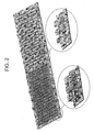
- this Fig. 2 has two SAW resonator units (1,2) on the same substrate, otherwise identical to Fig. 1 .
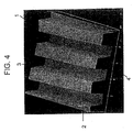
- Fig. 4 depicts an AFM picture of the reflector structures illustrated in Fig 1 . (9).
- the (1) represents the substrate.
- Number 2 represents a reflector structures.
- Numbers 3, 4 represent the dimensional of the micro channel between the reflector structures.
- Fig. 5 depicts a calculation scheme from the AFM picture shown in Fig. 4 . Here some examples of dimensions of the reflector and IDTE structures are illustrated.
- the microsensors disclosed herein include at least one surface acoustic wave sensor.
- a surface acoustic wave sensor includes a piezoelectric layer, or piezoelectric substrate, and input and output transducer(s).
- a surface acoustic wave is generated within the piezoelectric layer and is detected by interdigitated electrodes.
- binding events that alter the surface of the surface acoustic wave sensor can be detected as a change in a property of the propagating surface acoustic wave.
- Surface acoustic wave sensors are described in US patent Nos. 5,130,257 ; 5,283,037 ; and 5,306,644 ; F. Josse, et. al.
- Acoustic wave devices are described by the mode of wave propagation through or on a piezoelectric substrate. Acoustic waves are distinguished primarily by their velocities and displacement directions. Many combinations are possible, depending on the material and boundary conditions.
- the interdigital transducer electrode (IDTE) of each sensor provides the electric field necessary to displace the substrate and thus form an acoustic wave. The wave propagates through the substrate, where it is converted back to an electric field at the IDTE at the opposing electrode.
- Transverse, or shear, waves have particle displacements that are normal to the direction of wave propagation and which can be polarized so that the particle displacements are either parallel to or normal to the sensing surface. Shear horizontal wave motion signifies transverse displacements polarized parallel to the sensing surface; shear vertical motion indicates transverse displacements normal to the surface..
- “Surface acoustic wave sensor”, or “surface acoustic wave device” as used herein mean any device that operates substantially in the manner described above.
- “surface acoustic wave sensor” refers to both surface transverse wave devices, where the surface displacement is perpendicular to the direction of propagation and parallel to the device surface, as well as surface acoustic wave sensors where at least a portion of the surface displacement is perpendicular to the device surface. While surface transverse wave devices generally have better sensitivity in a fluid, it has been shown that sufficient sensitivity may also be achieved when a portion of the surface displacement is perpendicular to the device surface. See, for example, M. Rapp, et. al.
- the sensors are made by a photolithographic process. Manufacturing begins by carefully polishing and cleaning the piezoelectric substrate. Metal such as gold or aluminum is then deposited uniformly onto the substrate. The device is spin-coated with a photoresist and baked to harden it. It is then exposed to UV light through a mask with opaque areas corresponding to the areas to be metalized on the final device. The exposed areas undergo a chemical change that allows them to be removed with a developing solution. Finally, the remaining photoresist is removed. The pattern of metal remaining on the device is called an interdigital transducer (IDT) or interdigital electrodes (IDE). By changing the length, width, position, and thickness of the IDT, the performance of the sensor can be maximized.
- IDT interdigital transducer
- IDE interdigital electrodes
- the input and output transducers are preferably interdigitated transducers. Generally, there are two interdigital transducers. Each of the input and output transducers comprises two electrodes arranged in an interdigitated pattern. A voltage difference applied between the two electrodes of the input transducer results in the generation of a surface acoustic wave in the piezoelectric substrate.
- the electrodes generally may comprise any conductive material, with aluminum or gold being preferred.
- the electrode(s) may take any conventional form but are preferably photolithographically deposited on the surface as elongate regions of metallisation transverse to the direction of propagation of a wave along the surface of the support.
- the elongate metallised regions preferably have a width and spacing of the same order of magnitude. The width is typically between 1 and 40 microns, preferably between 10 and 20 microns.
- the width is greater than or equal to 100 nm, 200 nm, 300 nm, 400 nm, 500 nm, 600 nm, 700 nm, 800 nm, 900 nm, 1 micron, 2 microns, 3 microns, 4 microns, 5 microns, 7.5 microns, 10 microns, 15 microns, 20 microns, 25 microns, 30 microns, 35 microns, 40 microns, 45 microns, 50 microns, 60 microns, 70 microns, 80 microns or 90 microns.
- the space between the electrodes can be equal to or less than 100 microns, 90 microns, 80 microns, 70 microns, 60 microns, 50 microns, 45 microns, 40 microns, 35 microns, 30 microns, 25 microns, 20 microns, 15 microns, 10 microns, 7.5 microns, 5 microns, 4 microns, 3 microns, 2 microns 1 microns, 900 nm, 800 nm, 700 nm, 600 nm, 500 nm, 400 nm, 300 nm, 200 nm, 100 nm, or 75 nm. It should be noted that the spacing varies inversely with the frequency of the device.
- the height of the electrodes is the same as the width of the electrodes. In other embodiments, the height of the electrodes is, for example, greater than or equal to 10 nm, 20 nm, 30 nm, 40 nm, 50 nm, 75 nm, 100 nm, 200 nm, 300 nm, 400 nm, 500 nm, 600 nm, 700 nm, 800 nm, or 900 nm.
- the depth of the space between the electrodes can be less than or equal to 1 micron, 900 nm, 800 nm, 700 nm, 600 nm, 500 nm, 400 nm, 300 nm, 200 nm, 100 nm, 75 nm, 50 nm, 40 nm, 30 nm, or 20 nm.
- a single interdigital transducer In an alternative embodiment there is a single interdigital transducer.
- the single interdigital transducer serves both as both an input and output transducer.
- a reflector structure is generally provided to generate one or more resonances within the SAW sensor.
- the reflector structure may, for example, be a thin film grating.
- the grating may comprise aluminium, or another conductive material.
- the generated resonances can be detected, for example, by measuring the power dissipated at the single transducer.
- One or more binding events in the thin structure alter these resonances, allowing the binding events to be detected.
- An example of a sensor and technique according to this embodiment is generally described in US patent No. 5,846,708 , hereby incorporated by reference.
- other electronics and/or circuitry may similarly be utilized in an embodiment employing a SAW sensor having only one interdigital transducer.
- Molecular recognition molecules may be attached directly to self-assembled monolayers.
- a DNA probe molecule may be attached using a SH group on the 5' of the DNA using self-assembled monolayers as known in the art and described, for example, in K. Vijayamohanan et al. "Self-assembled monolayers as a tunable platform for biosensor applications," Biosensors & Bioelectronics 17 (2002) 1-12 and George M. Whitesides et al. "Array of Self-Assembled Monolayers for studing inhibition of Bacterial Adhesion.” Anal Chem 2002, 74, 1805-1810 , both of which are hereby incorporated by reference.
- the present invention especially relates to (1) a method for detecting an analyte in a sample comprising the following steps: (a) reacting the analyte in a sample with a first recognition component and a second enzyme-linked recognition component; and (b) adding a substrate which is converted into a precipitate by said linked enzyme; wherein, the steps (a) and (b) are executed in a reaction vessel segregate from the measuring chamber and wherein said precipitate obtained in step (b) is actively transported to said measuring chamber where it upon contact with the SAW sensor surface elicit an analyte specific signal.
- the present invention furthermore relates to (8) a device for detecting an analyte in a sample according to the method as the above (1) and/or as in one of the succeeding embodiments, comprising a reaction vessel with an inlet and an outlet in which the analyte specific precipitate is generated by enzyme conversion; connected to a measuring chamber with an inlet and an outlet comprising a SAW sensor; wherein, a liquid flow is actively transporting said precipitate from the reaction vessel to the measuring chamber where it comes into contact with the SAW sensor surface and elicits an analyte specific signal.
- the enzyme linked molecular recognition components may in some embodiments of the invention be substituted with nanoparticle linked molecular recognition components or nanoprobes.
- ALP Alkaline Phosphatase
- ALP conjugated antibody binds unspecifically to the gold and resin wall inside the sensor cavity and on the surface of the substrate. Such binding creates non specific BCIP/NBT precipitate and eventually give rice to an increase of the CV value.
- the BCIP/NBT precipitate in the SAW micro channels and on top of the SAW structures are not distributed as a plane layer all over the sensor structure (due to oscillating nature of the SAW sensor), but in a more random way on the sensor surface as illustrated at Fig. 4B - this also could give rice to increase of the CV value.
- Alkaline phosphatase method is an enzymatic process it can loose its activity over time due to temperature and handling issues. Also this could give rice to increase of the CV value.
- Atonomics has initiated the test of nano-gold conjugated antibodies instead of Alkaline phosphatase conjugated antibodies.
- the invention relates to a method for detecting a target analyte in a sample comprising the steps: (a) Reacting the analyte in a sample with a first molecular recognition component and a second molecular recognition component linked to at least one nanoparticle; and (b) Adding an enhancement solution comprising silver ions and/or gold ions, and a reducing agent, whereby the silver ions and/or gold ions are reduced to metallic silver and/or gold which is deposited onto the surface of the at least one nanoparticle; (c) detecting the mass increase of the at least one nanoparticle using a SAW sensor.
- Collodal gold (Au) and silver (Ag) particles and/or cluster complexes have been used in electron microscopy for labelling of target molecules. For example, cells that have such cluster complexes attached at a high density may appear dull red-purple in the microscope.
- Immunogold silver staining was discovered in 1981 and has since then been used for signal amplification/enhancement to improve the sensitivity of immunodetection systems that function as an alternative to chemiluminescence and radionuclide labelling.
- IGSS make small sized and small amounts of a target molecule detectable for visual inspection by e.g. microscope (such as light, electron, scanning etc.) and colorimetric absorbance.
- the Immunogold silver staining technology is based on the presence of silver ions and a reducing agent such as e.g. hydroquinone, colloidal gold particles will act as catalysts to reduce silver ions to metallic silver. The silver is deposited onto the gold particles thereby enlarging the particles.
- Some embodiments of the invention may use gold staining technology where the deposit covering a nanoparticle is acquired when gold ions in solution are catalytically deposited as metallic gold.
- the increase in particle mass due to the deposits may in some embodiments of the invention be detected by a surface acoustic wave (SAW) device.
- SAW surface acoustic wave
- the invention relates to a method wherein the first molecular reaction component is attached to the surface of the SAW sensor.
- the surface of the SAW sensor should if not otherwise specified be understood as the entire surface or as a part of the surface. Part of the surface may be understood as the IDT and/or the reflector structures, and it may also be understood as the surface within the micro channels of the IDT and/or reflector structures, or on top of these structures, or both within the channels and on top of the IDT and/or reflector structures.
- the first molecular reaction component may be attached as a single component or it may form part of a network/grid located at the surface of the SAW sensor.
- the first molecular recognition component may be comprised in a hydrogel as disclosed in US application 20060024813 .
- the invention relates to a method wherein the second molecular reaction component linked to at least one nanoparticle, wherein the nanoparticle is a gold particle.
- the gold particle may itself function as a catalyst during the reduction of silver ions and/or gold ions to metallic silver and/or gold deposits.
- Each second molecular reaction component may dependent on the size and nature of both the component itself and the nanoparticle be linked to at least one nanoparticle.
- further molecular recognition components, optionally linked to at least one nanoparticle may be included for the purpose of creating a network/grid structure and/or to amplify the detection signal of the method.
- the nanoparticle according to the invention has a diameter of 0,05; 0,1; 0,2; 0,3; 0,4; 0,5; 0,6; 0,7; 0,8; 0,9; 1; 2; 3; 4; 5; 6; 7; 8; 9; 10; 11; 12; 13; 14; 15; 16; 17; 18; 19 or 20 nm.
- the diameter (size) and thus the mass of the nanoparticle may vary depending on the particular analysis set up and required sensitivity.
- the nanoparticle diameter (size) and its mass (weight) for example the molecular weight of a gold particle with a diameter of 1 nm is 15.000 g/mol.
- the invention relates to a method wherein the nanoparticle has a diameter from 0.05 nm to 20 nm.
- a 10 nm size nanoparticle may increase in diameter to 300 nm within 5 minutes. Depending on the reaction time the diameter may increase to 500 nm or more.
- the deposits made from suitable materials such as silver or gold provides a mass increase of the nanoparticle that is detectable by a surface acoustic wave (SAW) device.
- SAW surface acoustic wave
- the invention furthermore relates to kit of parts comprising a microsensor for detecting an analyte in a sample, comprising: (a) a Surface Acoustic Wave sensor; comprising at least one first molecular recognition component immobilized to the surface of the SAW sensor; (b) at least one second molecular recognition component linked to at least one nanoparticle; (c) an enhancement solution comprising silver ions and/or gold ions; and (d) a reducing agent.
- a microsensor for detecting an analyte in a sample comprising: (a) a Surface Acoustic Wave sensor; comprising at least one first molecular recognition component immobilized to the surface of the SAW sensor; (b) at least one second molecular recognition component linked to at least one nanoparticle; (c) an enhancement solution comprising silver ions and/or gold ions; and (d) a reducing agent.
- the silver ions and/or gold ions are reduced to metallic silver and/or gold which is deposited onto the surface of the at least one nanoparticle; wherein the mass increase of the at least one nanoparticle is detected by the SAW sensor.
- EXAMPLE 1 Assay of anti-mouse IgG/anti-HFABP mAb-ALP.
- a micro sensor consisting of two SAW resonator units (Fig. 1.-1 , 2 ) was used.
- a SAW resonator unit three-dimensional surfaces ( Fig. 1.-1 ) were coated with 20 nm of gold.
- An identical SAW resonator unit three-dimensional surfaces ( Fig. 1.-2 ) were coated with SIO2.
- the gold surfaces of SAW resonator ( Fig. 1.-1 ) were incubated with 100 ug/ml goat anti-mouse IgG, while the SIO2 surface of SAW resonator ( Fig. 1.-2 ) were incubated with 100 ug/ml goat IgG.
- the first step was adsorption of the anti-mouse antibody on the gold coated three-dimensional SAW surface. This was performed by equilibration of the gold/SAW resonator unit with 2 uL of 100 ug/mL antibody in PBS buffer solution for 2 hours in a humid environment. Both SAW resonator units were then washed three times with PBS buffer containing 0.05% tween. After this treatment the two SAW resonator units ( Fig. 1-1 , 2 ) was incubated with 1 % BSA in PBS for 1 hour at room temperature in a humid environment. Both SAW resonator units was then washed three times with TBS buffer/0.05% tween. The two SAW resonators units ( Fig.
- the two SAW resonators units ( Fig. 1-1 , 2 ) were then exposed to 100 ng/ml of the mouse antibody (anti-HFABP mAb-ALP) label with an alkaline phosphatase enzyme (ALP) in PBS buffer for 15 minutes.
- ALP alkaline phosphatase enzyme
- SIGMA BCIP/NBT
- EXAMPLE 2 Assay of anti-mouse IgG/anti-HFABP mAb-2ALP.
- Sensitivity testing protocol consist of three steps: A. Sensor cleaning procedure (Hellmanex-II treatment); B. Coding the SAW sensors with conjugates antibodies; and C. Measurement procedures.
- EXAMPLE 4 Comparisons of sensitivity between Alkaline Phosphatase conjugated antibodies and gold conjugated antibodies.
- ALP Alkaline Phosphatase
- ALP conjugated antibody binds unspecifically to the gold and resin wall inside the sensor cavity and on the surface of the substrate. Such binding creates non specific BCIP/NBT precipitate and eventually give rice to an increase of the CV value.
- the BCIP/NBT precipitate in the SAW micro channels and on top of the SAW structures are not distributed as a plane layer all over the sensor structure (due to oscillating nature of the SAW sensor), but in a more random way on the sensor surface as illustrated at Fig. 4B - this also could give rice to increase of the CV value.
- Alkaline phosphatase method is an enzymatic process it can loose its activity over time due to temperature and handling issues. Also this could give rice to increase of the CV value.
- Atonomics has initiated the test of nano-gold conjugated antibodies instead of Alkaline phosphatase conjugated antibodies.
Landscapes
- Health & Medical Sciences (AREA)
- Immunology (AREA)
- Life Sciences & Earth Sciences (AREA)
- Engineering & Computer Science (AREA)
- Molecular Biology (AREA)
- Biomedical Technology (AREA)
- Chemical & Material Sciences (AREA)
- Hematology (AREA)
- Urology & Nephrology (AREA)
- Biotechnology (AREA)
- Microbiology (AREA)
- Cell Biology (AREA)
- Food Science & Technology (AREA)
- Medicinal Chemistry (AREA)
- Physics & Mathematics (AREA)
- Analytical Chemistry (AREA)
- Biochemistry (AREA)
- General Health & Medical Sciences (AREA)
- General Physics & Mathematics (AREA)
- Pathology (AREA)
- Investigating Or Analyzing Materials By The Use Of Ultrasonic Waves (AREA)
Claims (6)
- Verfahren zur Detektion eines Zielanalyten in einer Probe, wobei das Verfahren die Schritte umfasst:(a) Reaktion des Analyten in einer Probe mit einer ersten Komponente zur molekularen Erkennung und einer zweiten an mindestens ein Nanopartikel gebundenen Komponente zur molekularen Erkennung; und(b) Zugabe einer Verstärkungslösung enthaltend Silberionen und/oder Goldionen und ein Reduktionsmittel, wobei die Silberionen und/oder Goldionen zu metallischem Silber und/oder Gold reduziert werden, das auf der Oberfläche des mindestens einen Nanopartikels abgeschieden wird; und(c) Detektion des mindestens einen Nanopartikels enthaltend abgeschiedene Silberionen und/oder Goldionen mit einem SAW Sensor.
- Verfahren nach Anspruch 1, worin das Nanopartikel ein Goldpartikel ist.
- Verfahren nach einem der Ansprüche 1 oder 2, worin das Nanopartikel einen Durchmesser von 0, 05 nm bis 20 nm hat.
- Verfahren nach Anspruch 3, worin das Nanopartikel einen Durchmesser von 0,05; 0,1; 0,2; 0,3; 0,4; 0,5; 0,6; 0,7; 0,8; 0,9; 1; 2; 3; 4; 5; 6; 7; 8; 9; 10; 11; 12; 13; 14; 15; 16; 17; 18; 19 oder 20 nm hat.
- Verfahren nach einem der Ansprüche 1 - 4, worin ein Nanopartikel von etwa 10 nm Größe im Durchmesser auf 300 nm innerhalb von 5 Minuten wächst.
- Kit-of-Parts enthaltend einen Mikrosensor zur Detektion eines Analyten in einer Probe, enthaltend: (a) einen Oberflächenwellensensor; wobei der Oberflächenwellensensor mindestens eine erste Verbindung zur molekularen Erkennung enthält, aufgebracht auf die Oberfläche des SAW Sensors;(b) mindestens eine zweite Verbindung zur molekularen Erkennung gebunden an mindestens ein Nanopartikel;(c) eine Verstärkungslösung enthaltend Silberionen und/oder Goldionen; und(d) ein Reduktionsmittel.
Applications Claiming Priority (2)
| Application Number | Priority Date | Filing Date | Title |
|---|---|---|---|
| DKPA200700805 | 2007-06-01 | ||
| PCT/DK2008/000202 WO2008145130A1 (en) | 2007-06-01 | 2008-06-02 | Bio surface acoustic wave (saw) resonator amplification with nanoparticles for detection of a target analyte |
Publications (2)
| Publication Number | Publication Date |
|---|---|
| EP2156185A1 EP2156185A1 (de) | 2010-02-24 |
| EP2156185B1 true EP2156185B1 (de) | 2013-08-14 |
Family
ID=39705236
Family Applications (1)
| Application Number | Title | Priority Date | Filing Date |
|---|---|---|---|
| EP08758211.0A Not-in-force EP2156185B1 (de) | 2007-06-01 | 2008-06-02 | Biooberflächenwellenresonator, nachweis eines zielanalyten unter amplifizierung mit hilfe von nanopartikeln |
Country Status (5)
| Country | Link |
|---|---|
| US (1) | US20100105079A1 (de) |
| EP (1) | EP2156185B1 (de) |
| JP (1) | JP5276655B2 (de) |
| DK (1) | DK2156185T3 (de) |
| WO (1) | WO2008145130A1 (de) |
Families Citing this family (13)
| Publication number | Priority date | Publication date | Assignee | Title |
|---|---|---|---|---|
| KR20090070886A (ko) | 2007-12-27 | 2009-07-01 | 삼성전자주식회사 | 압전 센서를 이용한 바이오 센서에서 신호의 주파수변화량을 증폭하는 방법 |
| WO2011102065A1 (ja) * | 2010-02-17 | 2011-08-25 | 株式会社 村田製作所 | 質量検出センサーを用いた検出方法 |
| US10234425B2 (en) | 2013-03-15 | 2019-03-19 | Qorvo Us, Inc. | Thin film bulk acoustic resonator with signal enhancement |
| CN105431734B (zh) * | 2013-03-15 | 2018-10-02 | 快速诊断技术公司 | 信号增强的薄膜体声波谐振器 |
| CN105452858B (zh) | 2013-05-23 | 2019-10-01 | 快速诊断技术公司 | 两部分总成 |
| JP6285428B2 (ja) * | 2013-05-31 | 2018-02-28 | 京セラ株式会社 | センサ、検出方法、検出システム、および検出装置 |
| JP6216627B2 (ja) * | 2013-11-25 | 2017-10-18 | 日本電波工業株式会社 | 感知方法 |
| DK3194962T3 (da) | 2014-09-15 | 2019-07-01 | Qorvo Us Inc | Massedetektering via redoxkobling |
| GB201511687D0 (en) * | 2015-07-03 | 2015-08-19 | Foundation For Res And Technology Hellas Imbb Forth | Measurement of analyte with an acoustic wave sensor |
| KR101970327B1 (ko) * | 2017-04-13 | 2019-04-18 | 고려대학교 산학협력단 | 검출 신호의 자가 증폭 원리를 이용한 정확, 신속, 편리한 단일 단계 질병 진단 방법 |
| EP3652341A4 (de) * | 2017-07-11 | 2021-04-07 | Aviana Molecular Technologies, LLC | Signalverstärkung in einer biosensorvorrichtung |
| JP2021528664A (ja) | 2018-07-06 | 2021-10-21 | コーボ ユーエス,インコーポレイティド | ダイナミックレンジが拡大されたバルク音響波共振器 |
| EP3845901A4 (de) * | 2018-08-31 | 2022-05-18 | Asahi Kasei Kabushiki Kaisha | Sensibilisator zum nachweis eines analyts in einer probe und verfahren zum nachweis eines analyts in einer probe |
Family Cites Families (22)
| Publication number | Priority date | Publication date | Assignee | Title |
|---|---|---|---|---|
| US4235983A (en) * | 1978-10-04 | 1980-11-25 | Standard Oil Company (Indiana) | Purification of olefin recycle to polymerization |
| US5501986A (en) * | 1988-04-06 | 1996-03-26 | E. I. Du Pont De Nemours And Company | Piezoelectric specific binding assay with mass amplified reagents |
| US4999284A (en) * | 1988-04-06 | 1991-03-12 | E. I. Du Pont De Nemours And Company | Enzymatically amplified piezoelectric specific binding assay |
| WO1991005261A1 (en) * | 1989-10-04 | 1991-04-18 | E.I. Du Pont De Nemours And Company | Assay method for biological target complexes on the surface of a biosensor |
| US5478756A (en) * | 1990-07-24 | 1995-12-26 | Fisons Plc | Chemical sensor for detecting binding reactions |
| JPH06138125A (ja) * | 1992-08-20 | 1994-05-20 | Hitachi Chem Co Ltd | 水晶振動子を用いた抗原抗体反応の測定法 |
| JP3338551B2 (ja) * | 1994-03-17 | 2002-10-28 | 塩野義製薬株式会社 | ヒト血清アルブミンの測定方法 |
| IL114692A (en) * | 1995-07-21 | 1999-10-28 | Yissum Res Dev Co | Determination of an analyte in a liquid medium |
| US6582921B2 (en) * | 1996-07-29 | 2003-06-24 | Nanosphere, Inc. | Nanoparticles having oligonucleotides attached thereto and uses thereof |
| WO2002004681A2 (en) * | 2000-07-11 | 2002-01-17 | Northwestern University | Method of detection by enhancement of silver staining |
| JP2002202307A (ja) * | 2000-12-27 | 2002-07-19 | Iatron Lab Inc | イムノクロマトグラフ法 |
| FI118061B (fi) * | 2001-09-24 | 2007-06-15 | Beanor Oy | Menetelmä ja bioanturi analyysiä varten |
| GR1004178B (el) * | 2001-11-29 | 2003-03-05 | "����������" | Ολοκληρωμενος οπτοηλεκτρονικος βιοαισθητηρας πυριτιου για ανιχνευση βιομοριων επισημασμενων με χρωμοφορες ομαδες ή νανοσωματιδια |
| JP2003287541A (ja) * | 2002-03-28 | 2003-10-10 | Gc Corp | 齲蝕原性細菌検査キット及び齲蝕原性細菌検査方法 |
| CN100498278C (zh) * | 2002-05-28 | 2009-06-10 | 独立行政法人产业技术综合研究所 | 通过使用石英振荡器测量痕量物质的方法 |
| US20050250094A1 (en) * | 2003-05-30 | 2005-11-10 | Nanosphere, Inc. | Method for detecting analytes based on evanescent illumination and scatter-based detection of nanoparticle probe complexes |
| BRPI0418266A (pt) * | 2003-12-30 | 2007-05-02 | 3M Innovative Properties Co | método, meio legìvel por computador, e, sistema |
| WO2005064349A2 (en) * | 2003-12-30 | 2005-07-14 | 3M Innovative Properties Company | Detection cartridges, modules, systems and methods |
| JP2006275865A (ja) * | 2005-03-30 | 2006-10-12 | Citizen Watch Co Ltd | Qcmセンサーを用いた定量方法 |
| JP2006275864A (ja) * | 2005-03-30 | 2006-10-12 | Citizen Watch Co Ltd | Qcmセンサーを用いた定量方法 |
| WO2008019693A2 (en) * | 2006-08-17 | 2008-02-21 | Atonomics A/S | Bio surface acoustic wave (saw) resonator amplification for detection of a target analyte |
| KR20090070886A (ko) * | 2007-12-27 | 2009-07-01 | 삼성전자주식회사 | 압전 센서를 이용한 바이오 센서에서 신호의 주파수변화량을 증폭하는 방법 |
-
2008
- 2008-06-02 JP JP2010509677A patent/JP5276655B2/ja not_active Expired - Fee Related
- 2008-06-02 WO PCT/DK2008/000202 patent/WO2008145130A1/en not_active Ceased
- 2008-06-02 EP EP08758211.0A patent/EP2156185B1/de not_active Not-in-force
- 2008-06-02 DK DK08758211.0T patent/DK2156185T3/da active
- 2008-06-02 US US12/451,611 patent/US20100105079A1/en not_active Abandoned
Also Published As
| Publication number | Publication date |
|---|---|
| US20100105079A1 (en) | 2010-04-29 |
| DK2156185T3 (da) | 2013-11-18 |
| JP2010529422A (ja) | 2010-08-26 |
| JP5276655B2 (ja) | 2013-08-28 |
| EP2156185A1 (de) | 2010-02-24 |
| WO2008145130A1 (en) | 2008-12-04 |
Similar Documents
| Publication | Publication Date | Title |
|---|---|---|
| JP5020324B2 (ja) | 目標検体を検出するための、生体表面音響波(saw)共振器増幅 | |
| US20100105079A1 (en) | Bio surface acoustic wave (saw) resonator amplification with nanoparticles for detection of a target analyte | |
| Tom-Moy et al. | Atrazine measurements using surface transverse wave devices | |
| US7993854B2 (en) | Detection and quantification of biomarkers via a piezoelectric cantilever sensor | |
| Bunde et al. | Piezoelectric quartz crystal biosensors | |
| US5501986A (en) | Piezoelectric specific binding assay with mass amplified reagents | |
| US4999284A (en) | Enzymatically amplified piezoelectric specific binding assay | |
| Lee et al. | Surface acoustic wave immunosensor for real-time detection of hepatitis B surface antibodies in whole blood samples | |
| US10539537B2 (en) | Thin film bulk acoustic resonator with signal enhancement | |
| Lee et al. | Sensitive and simultaneous detection of cardiac markers in human serum using surface acoustic wave immunosensor | |
| Wang et al. | A silicon-based ultrasonic immunoassay for detection of breast cancer antigens | |
| Berkenpas et al. | Pure shear horizontal SAW biosensor on langasite | |
| Tigli et al. | Fabrication and characterization of a surface-acoustic-wave biosensor in CMOS technology for cancer biomarker detection | |
| EP2972295A1 (de) | Dünnschicht-volumenschallwellenresonator mit signalverstärkung | |
| Dahint et al. | Acoustic plate mode sensor for immunochemical reactions | |
| CN107250794B (zh) | 具有信号增强的薄膜体声波谐振器 | |
| AU2020245058B2 (en) | Detection of cardiac troponin or biological markers via shear horizontal surface acoustic wave biosensor using a wet-dry bioanalytical technique | |
| EP0408641B1 (de) | Piezoelektrscher spezifischer bindungstest mit einem reagens mit erhöhter masse | |
| WO2008019694A2 (en) | Bio surface acoustic wave (saw) resonator design for detection of a target analyte | |
| Fourati et al. | Immunosensing with surface acoustic wave sensors: toward highly sensitive and selective improved piezoelectric biosensors | |
| Lange et al. | Surface acoustic wave biosensors for biomolecular interaction analysis | |
| Tigli et al. | Surface acoustic wave based biosensor in CMOS for cancer biomarker detection |
Legal Events
| Date | Code | Title | Description |
|---|---|---|---|
| PUAI | Public reference made under article 153(3) epc to a published international application that has entered the european phase |
Free format text: ORIGINAL CODE: 0009012 |
|
| 17P | Request for examination filed |
Effective date: 20091217 |
|
| AK | Designated contracting states |
Kind code of ref document: A1 Designated state(s): AT BE BG CH CY CZ DE DK EE ES FI FR GB GR HR HU IE IS IT LI LT LU LV MC MT NL NO PL PT RO SE SI SK TR |
|
| AX | Request for extension of the european patent |
Extension state: AL BA MK RS |
|
| DAX | Request for extension of the european patent (deleted) | ||
| GRAP | Despatch of communication of intention to grant a patent |
Free format text: ORIGINAL CODE: EPIDOSNIGR1 |
|
| INTG | Intention to grant announced |
Effective date: 20130326 |
|
| GRAS | Grant fee paid |
Free format text: ORIGINAL CODE: EPIDOSNIGR3 |
|
| GRAA | (expected) grant |
Free format text: ORIGINAL CODE: 0009210 |
|
| AK | Designated contracting states |
Kind code of ref document: B1 Designated state(s): AT BE BG CH CY CZ DE DK EE ES FI FR GB GR HR HU IE IS IT LI LT LU LV MC MT NL NO PL PT RO SE SI SK TR |
|
| REG | Reference to a national code |
Ref country code: GB Ref legal event code: FG4D |
|
| REG | Reference to a national code |
Ref country code: AT Ref legal event code: REF Ref document number: 627127 Country of ref document: AT Kind code of ref document: T Effective date: 20130815 Ref country code: CH Ref legal event code: EP |
|
| REG | Reference to a national code |
Ref country code: IE Ref legal event code: FG4D |
|
| REG | Reference to a national code |
Ref country code: DE Ref legal event code: R096 Ref document number: 602008026782 Country of ref document: DE Effective date: 20131010 |
|
| REG | Reference to a national code |
Ref country code: DK Ref legal event code: T3 Effective date: 20131111 |
|
| REG | Reference to a national code |
Ref country code: NL Ref legal event code: T3 |
|
| REG | Reference to a national code |
Ref country code: AT Ref legal event code: MK05 Ref document number: 627127 Country of ref document: AT Kind code of ref document: T Effective date: 20130814 |
|
| REG | Reference to a national code |
Ref country code: LT Ref legal event code: MG4D |
|
| PG25 | Lapsed in a contracting state [announced via postgrant information from national office to epo] |
Ref country code: SE Free format text: LAPSE BECAUSE OF FAILURE TO SUBMIT A TRANSLATION OF THE DESCRIPTION OR TO PAY THE FEE WITHIN THE PRESCRIBED TIME-LIMIT Effective date: 20130814 Ref country code: HR Free format text: LAPSE BECAUSE OF FAILURE TO SUBMIT A TRANSLATION OF THE DESCRIPTION OR TO PAY THE FEE WITHIN THE PRESCRIBED TIME-LIMIT Effective date: 20130814 Ref country code: NO Free format text: LAPSE BECAUSE OF FAILURE TO SUBMIT A TRANSLATION OF THE DESCRIPTION OR TO PAY THE FEE WITHIN THE PRESCRIBED TIME-LIMIT Effective date: 20131114 Ref country code: PT Free format text: LAPSE BECAUSE OF FAILURE TO SUBMIT A TRANSLATION OF THE DESCRIPTION OR TO PAY THE FEE WITHIN THE PRESCRIBED TIME-LIMIT Effective date: 20131216 Ref country code: AT Free format text: LAPSE BECAUSE OF FAILURE TO SUBMIT A TRANSLATION OF THE DESCRIPTION OR TO PAY THE FEE WITHIN THE PRESCRIBED TIME-LIMIT Effective date: 20130814 Ref country code: IS Free format text: LAPSE BECAUSE OF FAILURE TO SUBMIT A TRANSLATION OF THE DESCRIPTION OR TO PAY THE FEE WITHIN THE PRESCRIBED TIME-LIMIT Effective date: 20131214 Ref country code: CY Free format text: LAPSE BECAUSE OF FAILURE TO SUBMIT A TRANSLATION OF THE DESCRIPTION OR TO PAY THE FEE WITHIN THE PRESCRIBED TIME-LIMIT Effective date: 20130821 Ref country code: LT Free format text: LAPSE BECAUSE OF FAILURE TO SUBMIT A TRANSLATION OF THE DESCRIPTION OR TO PAY THE FEE WITHIN THE PRESCRIBED TIME-LIMIT Effective date: 20130814 |
|
| PG25 | Lapsed in a contracting state [announced via postgrant information from national office to epo] |
Ref country code: PL Free format text: LAPSE BECAUSE OF FAILURE TO SUBMIT A TRANSLATION OF THE DESCRIPTION OR TO PAY THE FEE WITHIN THE PRESCRIBED TIME-LIMIT Effective date: 20130814 Ref country code: BE Free format text: LAPSE BECAUSE OF FAILURE TO SUBMIT A TRANSLATION OF THE DESCRIPTION OR TO PAY THE FEE WITHIN THE PRESCRIBED TIME-LIMIT Effective date: 20130814 Ref country code: GR Free format text: LAPSE BECAUSE OF FAILURE TO SUBMIT A TRANSLATION OF THE DESCRIPTION OR TO PAY THE FEE WITHIN THE PRESCRIBED TIME-LIMIT Effective date: 20131115 Ref country code: SI Free format text: LAPSE BECAUSE OF FAILURE TO SUBMIT A TRANSLATION OF THE DESCRIPTION OR TO PAY THE FEE WITHIN THE PRESCRIBED TIME-LIMIT Effective date: 20130814 Ref country code: FI Free format text: LAPSE BECAUSE OF FAILURE TO SUBMIT A TRANSLATION OF THE DESCRIPTION OR TO PAY THE FEE WITHIN THE PRESCRIBED TIME-LIMIT Effective date: 20130814 Ref country code: LV Free format text: LAPSE BECAUSE OF FAILURE TO SUBMIT A TRANSLATION OF THE DESCRIPTION OR TO PAY THE FEE WITHIN THE PRESCRIBED TIME-LIMIT Effective date: 20130814 |
|
| PG25 | Lapsed in a contracting state [announced via postgrant information from national office to epo] |
Ref country code: CY Free format text: LAPSE BECAUSE OF FAILURE TO SUBMIT A TRANSLATION OF THE DESCRIPTION OR TO PAY THE FEE WITHIN THE PRESCRIBED TIME-LIMIT Effective date: 20130814 |
|
| PG25 | Lapsed in a contracting state [announced via postgrant information from national office to epo] |
Ref country code: CZ Free format text: LAPSE BECAUSE OF FAILURE TO SUBMIT A TRANSLATION OF THE DESCRIPTION OR TO PAY THE FEE WITHIN THE PRESCRIBED TIME-LIMIT Effective date: 20130814 Ref country code: RO Free format text: LAPSE BECAUSE OF FAILURE TO SUBMIT A TRANSLATION OF THE DESCRIPTION OR TO PAY THE FEE WITHIN THE PRESCRIBED TIME-LIMIT Effective date: 20130814 Ref country code: SK Free format text: LAPSE BECAUSE OF FAILURE TO SUBMIT A TRANSLATION OF THE DESCRIPTION OR TO PAY THE FEE WITHIN THE PRESCRIBED TIME-LIMIT Effective date: 20130814 Ref country code: EE Free format text: LAPSE BECAUSE OF FAILURE TO SUBMIT A TRANSLATION OF THE DESCRIPTION OR TO PAY THE FEE WITHIN THE PRESCRIBED TIME-LIMIT Effective date: 20130814 |
|
| PG25 | Lapsed in a contracting state [announced via postgrant information from national office to epo] |
Ref country code: IT Free format text: LAPSE BECAUSE OF FAILURE TO SUBMIT A TRANSLATION OF THE DESCRIPTION OR TO PAY THE FEE WITHIN THE PRESCRIBED TIME-LIMIT Effective date: 20130814 Ref country code: ES Free format text: LAPSE BECAUSE OF FAILURE TO SUBMIT A TRANSLATION OF THE DESCRIPTION OR TO PAY THE FEE WITHIN THE PRESCRIBED TIME-LIMIT Effective date: 20130814 |
|
| PLBE | No opposition filed within time limit |
Free format text: ORIGINAL CODE: 0009261 |
|
| STAA | Information on the status of an ep patent application or granted ep patent |
Free format text: STATUS: NO OPPOSITION FILED WITHIN TIME LIMIT |
|
| 26N | No opposition filed |
Effective date: 20140515 |
|
| REG | Reference to a national code |
Ref country code: DE Ref legal event code: R097 Ref document number: 602008026782 Country of ref document: DE Effective date: 20140515 |
|
| PG25 | Lapsed in a contracting state [announced via postgrant information from national office to epo] |
Ref country code: LU Free format text: LAPSE BECAUSE OF FAILURE TO SUBMIT A TRANSLATION OF THE DESCRIPTION OR TO PAY THE FEE WITHIN THE PRESCRIBED TIME-LIMIT Effective date: 20140602 Ref country code: MC Free format text: LAPSE BECAUSE OF FAILURE TO SUBMIT A TRANSLATION OF THE DESCRIPTION OR TO PAY THE FEE WITHIN THE PRESCRIBED TIME-LIMIT Effective date: 20130814 |
|
| REG | Reference to a national code |
Ref country code: FR Ref legal event code: PLFP Year of fee payment: 8 |
|
| PGFP | Annual fee paid to national office [announced via postgrant information from national office to epo] |
Ref country code: DK Payment date: 20150625 Year of fee payment: 8 Ref country code: CH Payment date: 20150629 Year of fee payment: 8 Ref country code: DE Payment date: 20150629 Year of fee payment: 8 Ref country code: GB Payment date: 20150629 Year of fee payment: 8 |
|
| PGFP | Annual fee paid to national office [announced via postgrant information from national office to epo] |
Ref country code: IE Payment date: 20150630 Year of fee payment: 8 Ref country code: FR Payment date: 20150617 Year of fee payment: 8 Ref country code: NL Payment date: 20150626 Year of fee payment: 8 |
|
| PG25 | Lapsed in a contracting state [announced via postgrant information from national office to epo] |
Ref country code: MT Free format text: LAPSE BECAUSE OF FAILURE TO SUBMIT A TRANSLATION OF THE DESCRIPTION OR TO PAY THE FEE WITHIN THE PRESCRIBED TIME-LIMIT Effective date: 20130814 |
|
| PG25 | Lapsed in a contracting state [announced via postgrant information from national office to epo] |
Ref country code: BG Free format text: LAPSE BECAUSE OF FAILURE TO SUBMIT A TRANSLATION OF THE DESCRIPTION OR TO PAY THE FEE WITHIN THE PRESCRIBED TIME-LIMIT Effective date: 20130814 |
|
| PG25 | Lapsed in a contracting state [announced via postgrant information from national office to epo] |
Ref country code: TR Free format text: LAPSE BECAUSE OF FAILURE TO SUBMIT A TRANSLATION OF THE DESCRIPTION OR TO PAY THE FEE WITHIN THE PRESCRIBED TIME-LIMIT Effective date: 20130814 Ref country code: HU Free format text: LAPSE BECAUSE OF FAILURE TO SUBMIT A TRANSLATION OF THE DESCRIPTION OR TO PAY THE FEE WITHIN THE PRESCRIBED TIME-LIMIT; INVALID AB INITIO Effective date: 20080602 |
|
| REG | Reference to a national code |
Ref country code: DE Ref legal event code: R119 Ref document number: 602008026782 Country of ref document: DE |
|
| REG | Reference to a national code |
Ref country code: DK Ref legal event code: EBP Effective date: 20160630 |
|
| REG | Reference to a national code |
Ref country code: CH Ref legal event code: PL |
|
| REG | Reference to a national code |
Ref country code: NL Ref legal event code: MM Effective date: 20160701 |
|
| GBPC | Gb: european patent ceased through non-payment of renewal fee |
Effective date: 20160602 |
|
| REG | Reference to a national code |
Ref country code: IE Ref legal event code: MM4A |
|
| REG | Reference to a national code |
Ref country code: FR Ref legal event code: ST Effective date: 20170228 |
|
| PG25 | Lapsed in a contracting state [announced via postgrant information from national office to epo] |
Ref country code: LI Free format text: LAPSE BECAUSE OF NON-PAYMENT OF DUE FEES Effective date: 20160630 Ref country code: DE Free format text: LAPSE BECAUSE OF NON-PAYMENT OF DUE FEES Effective date: 20170103 Ref country code: FR Free format text: LAPSE BECAUSE OF NON-PAYMENT OF DUE FEES Effective date: 20160630 Ref country code: CH Free format text: LAPSE BECAUSE OF NON-PAYMENT OF DUE FEES Effective date: 20160630 |
|
| PG25 | Lapsed in a contracting state [announced via postgrant information from national office to epo] |
Ref country code: NL Free format text: LAPSE BECAUSE OF NON-PAYMENT OF DUE FEES Effective date: 20160701 Ref country code: IE Free format text: LAPSE BECAUSE OF NON-PAYMENT OF DUE FEES Effective date: 20160602 Ref country code: GB Free format text: LAPSE BECAUSE OF NON-PAYMENT OF DUE FEES Effective date: 20160602 |
|
| PG25 | Lapsed in a contracting state [announced via postgrant information from national office to epo] |
Ref country code: DK Free format text: LAPSE BECAUSE OF NON-PAYMENT OF DUE FEES Effective date: 20160630 |