EP2156210B1 - Verfahren zur messung von ankommenden winkeln kohärenter quellen unter verwendung von raumglättung in einem beliebigen sensornetzwerk - Google Patents
Verfahren zur messung von ankommenden winkeln kohärenter quellen unter verwendung von raumglättung in einem beliebigen sensornetzwerk Download PDFInfo
- Publication number
- EP2156210B1 EP2156210B1 EP08760729A EP08760729A EP2156210B1 EP 2156210 B1 EP2156210 B1 EP 2156210B1 EP 08760729 A EP08760729 A EP 08760729A EP 08760729 A EP08760729 A EP 08760729A EP 2156210 B1 EP2156210 B1 EP 2156210B1
- Authority
- EP
- European Patent Office
- Prior art keywords
- interpolation
- sectors
- verifying
- exp
- calculating
- Prior art date
- Legal status (The legal status is an assumption and is not a legal conclusion. Google has not performed a legal analysis and makes no representation as to the accuracy of the status listed.)
- Not-in-force
Links
Images


Classifications
-
- G—PHYSICS
- G01—MEASURING; TESTING
- G01S—RADIO DIRECTION-FINDING; RADIO NAVIGATION; DETERMINING DISTANCE OR VELOCITY BY USE OF RADIO WAVES; LOCATING OR PRESENCE-DETECTING BY USE OF THE REFLECTION OR RERADIATION OF RADIO WAVES; ANALOGOUS ARRANGEMENTS USING OTHER WAVES
- G01S3/00—Direction-finders for determining the direction from which infrasonic, sonic, ultrasonic or electromagnetic waves, or particle emission, not having a directional significance, are being received
- G01S3/02—Direction-finders for determining the direction from which infrasonic, sonic, ultrasonic or electromagnetic waves, or particle emission, not having a directional significance, are being received using radio waves
- G01S3/74—Multi-channel systems specially adapted for direction-finding, i.e. having a single antenna system capable of giving simultaneous indications of the directions of different signals
-
- G—PHYSICS
- G01—MEASURING; TESTING
- G01S—RADIO DIRECTION-FINDING; RADIO NAVIGATION; DETERMINING DISTANCE OR VELOCITY BY USE OF RADIO WAVES; LOCATING OR PRESENCE-DETECTING BY USE OF THE REFLECTION OR RERADIATION OF RADIO WAVES; ANALOGOUS ARRANGEMENTS USING OTHER WAVES
- G01S13/00—Systems using the reflection or reradiation of radio waves, e.g. radar systems; Analogous systems using reflection or reradiation of waves whose nature or wavelength is irrelevant or unspecified
Definitions
- the invention relates to a method for interpolating direction vectors of any sensor array using omnidirectional modal functions.
- It also relates to a method and a system that makes it possible, in particular, to estimate coherent source arrival angles by a smoothing technique on any sensor network.
- It can also be used in medical imaging processes to locate tumors or epileptic foci.
- the technical field is that of antenna processing which processes the signals of several transmitting sources from a multi-sensor reception system.
- the sensors are antennas and the radio sources propagate in a polarization.
- the sensors are microphones and the sources are sound.
- the figure 1 shows that an antenna processing system is composed of a network of sensors receiving sources with different arrival angles ⁇ mp .
- the domain is, for example, that of direction finding which consists of estimating the arrival angles of the sources.
- the elementary sensors of the network receive the sources with a phase and an amplitude depending in particular on their angles of incidence and the position of the sensors.
- the angles of incidence are parameterized in 1D by the azimuth ⁇ m and in 2D by the azimuth ⁇ m and the elevation ⁇ m .
- a direction finding 1D is defined by techniques that estimate only the azimuth by supposing that the waves of the sources propagate in the plane of the network of sensors.
- the direction finding technique jointly estimates the azimuth and the elevation of a source, it is a question of 2D direction finding.
- Antenna processing techniques aim to exploit the spatial diversity of using the position of network antennas to better utilize differences in incidence and distance from sources.
- the figure 3 illustrates an application to direction finding in the presence of multipaths.
- the m -th source propagates along paths P of incidence ⁇ mp (1 ⁇ p ⁇ P) that are caused by P -1 obstacles in the radio environment.
- the problem addressed in the method according to the invention is, in particular, the case of coherent paths where the propagation time difference between the direct path and a secondary path is much smaller than the inverse of the signal band.
- the technical problem to be solved is also that of the direction finding of paths consistent with a reduced calculation cost and a network of sensors of any geometry.
- one of the objectives of the method according to the invention is to implement these techniques on any sensor networks.
- the algorithms for handling the case of coherent sources are, for example, the Maximum Likelihood algorithms [2] [3] that are applicable on any geometric sensor networks.
- these algorithms require multi-parameter estimations which induce an implementation with a high calculation cost.
- the maximum likelihood technique is adapted to the cases of linear sensor arrays equi-spaced by the IQML or MODE methods [7] [8].
- Another alternative is that of spatial smoothing techniques [4] [5] which have the advantage of treating coherent sources with a low calculation cost.
- the low-cost direction finding techniques adapted to linear arrays are either the ESPRIT [9] [10] method or Root [11] [12] techniques that look for the roots of a polynomial.
- the invention relates to a method for determining coherent source arrival angles in a system comprising a plurality of arbitrary sensors, the signals propagating along coherent or substantially coherent paths between a source and said network receiving sensors, according to the claim. 1.
- n ( t ) is the additive noise
- a ( ⁇ ) is the response of the sensor array to a direction source ⁇ and ⁇ mp , ⁇ mp , ⁇ mp are the attenuation, the direction and the delay respectively.
- p -th path the m -th source.
- a ( ⁇ m , ⁇ m ) is the response of the sensor array to the m-th source
- ⁇ m [ ⁇ ml ⁇ ⁇ mP m ] T
- ⁇ m [ ⁇ m l ⁇ ⁇ mP m ] T.
- the source vector of the source is no longer a ( ⁇ m 1 ) but a composite director vector a ( ⁇ m , ⁇ m ) which is different and which depends on a number of larger parameters.
- the purpose of the spatial smoothing techniques is to apply a pre-processing on the covariance matrix R x of the multi-sensor signal which increases the rank of the matrix R s of covariance of the sources in order to be able to apply MUSIC type algorithms. or any other algorithm having equivalent functionality in the presence of coherent sources without the need to apply a maximum likelihood type algorithm.
- rank ⁇ R s ⁇ ⁇ rang ⁇ R s SM ⁇ ⁇ min ( l ⁇ rank ⁇ R s ⁇ , ⁇ m 1 M P m ) .
- the Forward-Backward [4] spatial smoothing technique requires a network of sensors having a center of symmetry. Under these conditions the director vector verifies:
- Spatial smoothing and Forward-Backward techniques can be combined to increase decorrelation capacity in number of trips. These smoothing techniques make it possible to treat coherent sources with a calculation cost similar to the MUSIC method.
- these techniques require geometries of very particular sensor networks. It should be noted that these particular network geometries are almost impossible to design in the presence of mutual coupling between the sensors or coupling with the carrier structure of the sensor network.
- the object of the present invention relates in particular to the application of these techniques to networks of any geometry.
- These transformations are carried out by an interpolation process according to the invention comprising the steps described below by way of illustration and in no way limiting.
- the transformation takes place, for example, in applying an interpolation matrix on the sensor signals (signals received by the sensors of a network) and makes it possible to obtain an equivalent director vector e ( ⁇ ) which verifies the remarkable properties of the equations (7) and / or (13) .
- the invention also relates to a method for interpolating direction vectors, vectors depending on the positions of the sensors of a network that receives signals.
- the matrix W of dimension N ⁇ ( 2 L + 1 ), not necessarily square, is obtained by minimizing in the least squares sense the difference ⁇ a ( ⁇ ) - We ( ⁇ ) ⁇ 2 for azimuths satisfying 0 ⁇ ⁇ ⁇ 360 ° .
- the length of the 2 L +1 interpolation depends on the opening of the network.
- This value is associated with a 0.7 ° phase error which corresponds to an uncertainty in the measurement of the direction vectors a ( ⁇ ) during a calibration phase.
- FIG. 7 The dependence between the parameter L of the interpolation and the ratio R / ⁇ is illustrated figure 7 .
- ⁇ for R / ⁇ 0.5 and shows that A_dB ( ⁇ ) is well below 0.1dB for
- a spatial smoothing technique is applied to an interpolated network, by sector.
- ⁇ are disjoint (see figure 8 and figure 9 ).
- W ij e ( ⁇ ) is the interpolation function of the director vector a ( ⁇ ) on two sectors because a ( ⁇ ) ⁇ W ij e ( ⁇ ) when
- the matrices W ij are obtained by minimizing the difference ⁇ a ( ⁇ ) - W ij e ( ⁇ ) ⁇ 2 in the least squares sense for
- a spatial smoothing technique can be used to decorrelate coherent multipaths in the interval
- ⁇ then apply a direction finding algorithm such as ESPRIT.
- ESPRIT direction finding algorithm
- ⁇ are solutions.
- W i1 ... 1P e ( ⁇ ) is an interpolation function (a ( ⁇ ) ⁇ W i1 ... iP e ( ⁇ ) when
Landscapes
- Engineering & Computer Science (AREA)
- Radar, Positioning & Navigation (AREA)
- Remote Sensing (AREA)
- Physics & Mathematics (AREA)
- General Physics & Mathematics (AREA)
- Computer Networks & Wireless Communication (AREA)
- Complex Calculations (AREA)
- Radar Systems Or Details Thereof (AREA)
- Measurement Of Velocity Or Position Using Acoustic Or Ultrasonic Waves (AREA)
- Measurement Of Mechanical Vibrations Or Ultrasonic Waves (AREA)
- Optical Radar Systems And Details Thereof (AREA)
- Air Conditioning Control Device (AREA)
- Investigating Or Analyzing Materials By The Use Of Ultrasonic Waves (AREA)
Claims (5)
- Verfahren zum Ermitteln von Ankunftswinkeln von kohärenten Quellen in einem System, das mehrere beliebige Sensoren umfasst, wobei sich die Signale über kohärente oder im Wesentlichen kohärente Bahnen zwischen einer Quelle und den Empfangssensoren des Netzes ausbreiten, dadurch gekennzeichnet, dass wenigstens eine modale, im Azimuth omnidirektionale Interpolationsfunktion z(θ) k angewendet wird, wobei z(θ)=exp(jθ), wobei θ einem Winkelsektor entspricht, auf dem die Interpolation von Richtungsvektoren a (θ) des Sensornetzes durchgeführt wird, um die von den Quellen ausgesendeten und auf dem Sensornetz empfangenen Signale zu verarbeiten, und eine Raumglättungstechnik zum Entkoppeln der kohärenten Quellen angewendet wird, wobei die Interpolationsfunktion W e(θ) wie folgt ausgedrückt wird:

wobei die Matrix W der Dimension N x (2L+1) erhalten wird, indem im Sinne der kleinsten Quadrate die Abweichung ∥a(θ)-We (θ)∥2 für Azimuthe, die 0≤θ<360° erfüllen, minimiert wird, wobei die Länge der Interpolation 2L+1 von der Öffnung des Netzes abhängt, dadurch gekennzeichnet, dass die Interpolationsfunktion mehrere Interpolationsmatrizen Wi1...iP umfasst, wobei P der Zahl der disjunkten Sektoren entspricht, an denen die konjunkte Interpolation der empfangenen Signale erfolgt, wobei die Ermittlung der Matrix sowie der Interpolationsbreite δθ jedes Sektors wenigstens die folgenden Schritte beinhaltet:Schritt A.1: δθ = 180°/P und θ ip = 2δθ (p - 1) für 1 ≤ p ≤ P;Schritt A.2: Berechnen der Interpolationsmatrix Wi1...iP, indem im Sinne der kleinsten Quadrate ∥a(θ) - W i1 ...ip e(θ)∥2 für |θ - θ iP | < δθ und 1 ≤ p ≤ P minimiert wird;Schritt A.3: Berechnen des Kriteriums A_dB(ê1(θ),ê2(θ))
wobei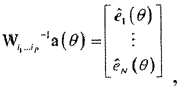
wobei δθ der kleinste Wert ist, für den der Amplitudenfehler A_dB kleiner als ein gegebener Wert A_dB_ref ist;Schritt A.4: wenn A_dB(ê1(θ),ê2 (θ))>A_dB_ref ist, dann δθ = δθ /2 durchführen und zu Schritt A.2 zurückkehren;Schritt A.5: Berechnen von K = 180 / (Pδθ);Schritt A.6: für alle P-uplets (i1...ip), die 0 ≤ i1 ≤ ... ≤ ip < K erfüllen, wobei K die Zahl der Sektoren ist, an denen die Interpolation durchgeführt wird:Schritt A.6.1: Berechnen von θ ip = 2δθ x ip für 1 ≤ p ≤ P;Schritt A.6.2: Berechnen der Interpolationsmatrix Wi1...iP durch Minimieren im Sinne der kleinsten Quadrate ∥a(θ)-W i1 ...ip e(θ)∥2 für |θ - θ ip | < δθ und 1 ≤ p ≤ P;Schritt A.6.3: Zurückkehren zu Schritt A.6.1, wenn noch nicht alle P-uplets (i1...ip) die 1 ≤ i1 ≤ ... ≤ ip < K erfüllen, untersucht wurden. - Verfahren nach Anspruch 1, dadurch gekennzeichnet, dass der Wert von L wie folgt bestimmt wird:

wobei L der kleinste Wert ist, der A_dB kleiner als 0,1 dB erfüllt; in der Tat ist A_dB null, wenn die Interpolation perfekt ist und somit wenn a(θ) = We (θ). - Verfahren nach Anspruch 2, dadurch gekennzeichnet, dass für die Netze, bei denen die Länge der Interpolation 2L+1 größer als N ist, das Netz durch K Sektoren der Breite δθ = 180° / K mit quadratischen Interpolationsmatrizen Wk interpoliert wird,
wobei
wobei die K Matrizen Wk quadratisch sind, wobei N = 2L0 + 1,
die Matrizen Wk werden erhalten, indem die Abweichung ∥a(θ)-W k ,e(θ)∥2 im Sinne der kleinsten Quadrate für |θ-θ k |<δθ minimiert wird;
die Breite des Interpolationskonus δθ wird anhand des folgenden Amplitudenfehlerkriteriums bestimmt:
wobei δθ der kleinste Wert ist, der A_dB kleiner als 0,1 dB erfüllt, da A_dB null ist, wenn a(θ) = Wke (θ). - Verfahren nach einem der Ansprüche 1 bis 3, dadurch gekennzeichnet, dass es einen Goniometrieschritt beinhaltet, der wenigstens die folgenden Schritte beinhaltet:Schritt B.0: Initialisieren eines Satzes Θ bis Ø;Schritt B: Für alle P-uplets (i1...ip), die 0 ≤ i1 ≤ ... ≤ ip < K erfüllen:Schritt B.1: Berechnen von yi1...ip (t) = Wi1...ip -1x(t);Schritt B.2: Berechnen der θip = 2δθ x ip für 1 ≤ p ≤ P;Schritt B.3: Anwenden einer Raumglättungs- und/oder Forward-Backward-Technik auf die Beobachtung yi1...ip (t), dann Anwenden eines Goniometriealgorithmus, um die θ̂ k Indexe für 1 ≤ k ≤Ki1...ip zu erhalten;Schritt B.4: Auswählen der geschätzten Fälle von θ̂k ∈ Θ i
1 .... ip , wobei Θ i1 ...ip ={ |θ̂k-θ ip | < δθ für 1 ≤ p ≤ P und JMUSIC (θ̂) < ηSchritt B.5: Θ=Θ∪Θi1 ...i p Sätze von Einfallswinkeln, die Schritt B.4 für alle Sektoren erfüllen, die mit den P-uplets (i1...ip) assoziiert sind, die mit dem Algorithmus bearbeitet wurden;Schritt B.6: Zurückkehren zu Schritt B.1, solange nicht alle P-uplets (i1...ip), die 0 ≤ i1 ≤ ... ≤ ip < K erfüllen, untersucht wurden. - Verfahren nach Anspruch 1, dadurch gekennzeichnet, dass für die kohärenten Quellen, die in den verschiedenen Sektoren vorhanden sind, gemeinsam der Richtungsvektor a(θ) auf mehreren Sektoren interpoliert wird.
Applications Claiming Priority (2)
| Application Number | Priority Date | Filing Date | Title |
|---|---|---|---|
| FR0704113A FR2917180B1 (fr) | 2007-06-08 | 2007-06-08 | Procede d'estimation des angles d'arrivees de sources coherentes par une technique de lissage spatial sur un reseau de capteurs quelconque |
| PCT/EP2008/057165 WO2008155250A1 (fr) | 2007-06-08 | 2008-06-09 | Procede d'estimation des angles d'arrivees de sources coherentes par une technique de lissage spatial sur un reseau de capteurs quelconque |
Publications (2)
| Publication Number | Publication Date |
|---|---|
| EP2156210A1 EP2156210A1 (de) | 2010-02-24 |
| EP2156210B1 true EP2156210B1 (de) | 2010-09-22 |
Family
ID=38917367
Family Applications (1)
| Application Number | Title | Priority Date | Filing Date |
|---|---|---|---|
| EP08760729A Not-in-force EP2156210B1 (de) | 2007-06-08 | 2008-06-09 | Verfahren zur messung von ankommenden winkeln kohärenter quellen unter verwendung von raumglättung in einem beliebigen sensornetzwerk |
Country Status (8)
| Country | Link |
|---|---|
| US (1) | US8248304B2 (de) |
| EP (1) | EP2156210B1 (de) |
| CN (1) | CN101779140B (de) |
| AT (1) | ATE482409T1 (de) |
| DE (1) | DE602008002759D1 (de) |
| FR (1) | FR2917180B1 (de) |
| IL (1) | IL202540A (de) |
| WO (1) | WO2008155250A1 (de) |
Families Citing this family (12)
| Publication number | Priority date | Publication date | Assignee | Title |
|---|---|---|---|---|
| FR2940461B1 (fr) * | 2008-12-23 | 2011-01-21 | Thales Sa | Procede de determination des angles d'arrivee en azimut et en elevation de sources coherentes |
| JP5931661B2 (ja) | 2012-09-14 | 2016-06-08 | 本田技研工業株式会社 | 音源方向推定装置、音源方向推定方法、及び音源方向推定プログラム |
| CN103269526B (zh) * | 2013-05-23 | 2016-08-24 | 山西煤炭运销集团有限公司 | 一种用于矿井巷道的无线传感器网络 |
| CN104020439B (zh) * | 2014-06-20 | 2016-06-29 | 西安电子科技大学 | 基于空间平滑协方差矩阵稀疏表示的波达方向角估计方法 |
| CN104833947B (zh) * | 2015-04-03 | 2017-10-31 | 西北大学 | 一种任意阵接收对称虚拟变换2d‑doa分离算法 |
| CN105242264B (zh) * | 2015-11-26 | 2018-06-19 | 上海无线电设备研究所 | 一种平面阵列多目标角度高分辨实现方法 |
| CN107315162B (zh) * | 2017-07-25 | 2020-05-22 | 西安交通大学 | 基于内插变换和波束形成的远场相干信号doa估计方法 |
| CN108828667B (zh) * | 2018-03-23 | 2019-09-03 | 中国矿业大学(北京) | 一种微地震复杂地表高程校正方法 |
| TWI666001B (zh) * | 2018-06-11 | 2019-07-21 | 緯創資通股份有限公司 | 分析生理訊號的方法及相關分析裝置 |
| JP2022511271A (ja) * | 2018-08-23 | 2022-01-31 | ボード オブ リージェンツ,ザ ユニバーシティ オブ テキサス システム | 音響信号を用いて手の動きを追跡することによる装置の制御 |
| CN112255625B (zh) * | 2020-09-01 | 2023-09-22 | 杭州电子科技大学 | 基于深度学习的二维角度依赖误差下的一维线阵测向方法 |
| DE102022210263A1 (de) * | 2022-09-28 | 2024-03-28 | Robert Bosch Gesellschaft mit beschränkter Haftung | Verfahren zur Steuerung eines kohärenten kooperativen Radarsensornetzwerks |
Family Cites Families (2)
| Publication number | Priority date | Publication date | Assignee | Title |
|---|---|---|---|---|
| CA2506779A1 (en) * | 2002-11-22 | 2004-06-10 | Ben Gurion University | Smart antenna system with improved localization of polarized sources |
| CN1808949A (zh) * | 2005-12-23 | 2006-07-26 | 西安交通大学 | 多输入多输出通信系统信道的一种非物理建模与仿真方法 |
-
2007
- 2007-06-08 FR FR0704113A patent/FR2917180B1/fr not_active Expired - Fee Related
-
2008
- 2008-06-09 US US12/663,561 patent/US8248304B2/en not_active Expired - Fee Related
- 2008-06-09 AT AT08760729T patent/ATE482409T1/de not_active IP Right Cessation
- 2008-06-09 WO PCT/EP2008/057165 patent/WO2008155250A1/fr not_active Ceased
- 2008-06-09 CN CN2008801024453A patent/CN101779140B/zh not_active Expired - Fee Related
- 2008-06-09 EP EP08760729A patent/EP2156210B1/de not_active Not-in-force
- 2008-06-09 DE DE602008002759T patent/DE602008002759D1/de active Active
-
2009
- 2009-12-06 IL IL202540A patent/IL202540A/en not_active IP Right Cessation
Also Published As
| Publication number | Publication date |
|---|---|
| IL202540A (en) | 2014-08-31 |
| FR2917180B1 (fr) | 2010-05-14 |
| US8248304B2 (en) | 2012-08-21 |
| ATE482409T1 (de) | 2010-10-15 |
| CN101779140A (zh) | 2010-07-14 |
| WO2008155250A1 (fr) | 2008-12-24 |
| US20110025563A1 (en) | 2011-02-03 |
| DE602008002759D1 (de) | 2010-11-04 |
| IL202540A0 (en) | 2010-06-30 |
| CN101779140B (zh) | 2013-07-17 |
| EP2156210A1 (de) | 2010-02-24 |
| FR2917180A1 (fr) | 2008-12-12 |
Similar Documents
| Publication | Publication Date | Title |
|---|---|---|
| EP2156210B1 (de) | Verfahren zur messung von ankommenden winkeln kohärenter quellen unter verwendung von raumglättung in einem beliebigen sensornetzwerk | |
| EP2368129B1 (de) | Verfahren zur bestimmung von azimuth- und erhebungswinkeln der ankunft kohärenter quellen | |
| EP1759435B1 (de) | Multiparametrisches richtungsfindungsverfahren mit trennung von ereignis- und störungsparametern | |
| EP1259833B1 (de) | Verfahren zum orten von funkquellen mittels eines hochauflösenden zweikanaligen funkpeilers | |
| Blunt et al. | Robust DOA estimation: The reiterative superresolution (RISR) algorithm | |
| EP2215492B1 (de) | Verfahren zur mehrsender- und mehrwege-aoa-tdoa-lokalisierung, mit einem subverfahren zum synchronisieren und entzerren der empfangsstationen | |
| JP4722132B2 (ja) | 到来波数推定方法、到来波数推定装置及び無線装置 | |
| WO2010072593A1 (fr) | Procede de localisation par estimation multi-voies des tdoa et fdoa des multi-trajets d'une source avec ou sans aoa | |
| EP0926510B1 (de) | Verfahren zur Positionsbestimmung von mobilen Objekten im Stadtverkehr | |
| EP2428810A1 (de) | Geo-Lokalisierungsverfahren mit mehreren Sender mit räumlich-zeitlicher Behandlung | |
| Bosse et al. | A spatio-temporal array processing for passive localization of radio transmitters | |
| Park et al. | Maximum‐likelihood angle estimator for multi‐channel FM‐radio‐based passive coherent location | |
| EP2517037B1 (de) | Verfahren zur kalkulation der anzahl von störquellen einer sensoranordnung mittels kalkulation von rauschstatistiken | |
| Foroozan et al. | Time reversal based active array source localization | |
| Gong et al. | Joint DOD and DOA estimation for bistatic multiple‐input multiple‐output radar target discrimination based on improved unitary ESPRIT method | |
| EP1869489B1 (de) | Verfahren und einrichtung zur hochauflösenden richtungsfindung willkürlicher gerader ordnung | |
| Shi et al. | DOA estimation for mixed uncorrelated and coherent sources in multipath environment | |
| EP2458398A2 (de) | Verfahren zur Optimierung eines Netzes aus heterogenen Sensoren für die Goniometrie | |
| CN114487985A (zh) | 一种基于差-和信号的波束锐化方法及系统 | |
| EP2857856B1 (de) | Goniometrieverfahren mit einem System, das über weniger Empfangswege als Sensoren verfügt | |
| EP2607917B1 (de) | Verfahren und System zum Lokalisieren von einem oder mehreren Sendern innerhalb eines Antennennetzes mit Antennen unterschiedlicher Polarisierung | |
| Chu et al. | Beam-space spatial spectrum reconstruction under unknown stationary near-field interference: Algorithm design and experimental verification | |
| Shevchenko et al. | Direction Finding of Multipath Signals | |
| Wan et al. | An approach to manifold estimation for antenna array in situation of interferences | |
| Kim et al. | DOA estimation using time-frequency conversion pre-processing method |
Legal Events
| Date | Code | Title | Description |
|---|---|---|---|
| PUAI | Public reference made under article 153(3) epc to a published international application that has entered the european phase |
Free format text: ORIGINAL CODE: 0009012 |
|
| 17P | Request for examination filed |
Effective date: 20091216 |
|
| AK | Designated contracting states |
Kind code of ref document: A1 Designated state(s): AT BE BG CH CY CZ DE DK EE ES FI FR GB GR HR HU IE IS IT LI LT LU LV MC MT NL NO PL PT RO SE SI SK TR |
|
| AX | Request for extension of the european patent |
Extension state: AL BA MK RS |
|
| GRAP | Despatch of communication of intention to grant a patent |
Free format text: ORIGINAL CODE: EPIDOSNIGR1 |
|
| GRAS | Grant fee paid |
Free format text: ORIGINAL CODE: EPIDOSNIGR3 |
|
| GRAA | (expected) grant |
Free format text: ORIGINAL CODE: 0009210 |
|
| AK | Designated contracting states |
Kind code of ref document: B1 Designated state(s): AT BE BG CH CY CZ DE DK EE ES FI FR GB GR HR HU IE IS IT LI LT LU LV MC MT NL NO PL PT RO SE SI SK TR |
|
| REG | Reference to a national code |
Ref country code: GB Ref legal event code: FG4D Free format text: NOT ENGLISH |
|
| REG | Reference to a national code |
Ref country code: CH Ref legal event code: EP |
|
| REG | Reference to a national code |
Ref country code: IE Ref legal event code: FG4D Free format text: LANGUAGE OF EP DOCUMENT: FRENCH |
|
| REF | Corresponds to: |
Ref document number: 602008002759 Country of ref document: DE Date of ref document: 20101104 Kind code of ref document: P |
|
| PG25 | Lapsed in a contracting state [announced via postgrant information from national office to epo] |
Ref country code: LT Free format text: LAPSE BECAUSE OF FAILURE TO SUBMIT A TRANSLATION OF THE DESCRIPTION OR TO PAY THE FEE WITHIN THE PRESCRIBED TIME-LIMIT Effective date: 20100922 Ref country code: AT Free format text: LAPSE BECAUSE OF FAILURE TO SUBMIT A TRANSLATION OF THE DESCRIPTION OR TO PAY THE FEE WITHIN THE PRESCRIBED TIME-LIMIT Effective date: 20100922 Ref country code: NO Free format text: LAPSE BECAUSE OF FAILURE TO SUBMIT A TRANSLATION OF THE DESCRIPTION OR TO PAY THE FEE WITHIN THE PRESCRIBED TIME-LIMIT Effective date: 20101222 |
|
| REG | Reference to a national code |
Ref country code: NL Ref legal event code: VDEP Effective date: 20100922 |
|
| LTIE | Lt: invalidation of european patent or patent extension |
Effective date: 20100922 |
|
| PG25 | Lapsed in a contracting state [announced via postgrant information from national office to epo] |
Ref country code: SI Free format text: LAPSE BECAUSE OF FAILURE TO SUBMIT A TRANSLATION OF THE DESCRIPTION OR TO PAY THE FEE WITHIN THE PRESCRIBED TIME-LIMIT Effective date: 20100922 Ref country code: PL Free format text: LAPSE BECAUSE OF FAILURE TO SUBMIT A TRANSLATION OF THE DESCRIPTION OR TO PAY THE FEE WITHIN THE PRESCRIBED TIME-LIMIT Effective date: 20100922 Ref country code: HR Free format text: LAPSE BECAUSE OF FAILURE TO SUBMIT A TRANSLATION OF THE DESCRIPTION OR TO PAY THE FEE WITHIN THE PRESCRIBED TIME-LIMIT Effective date: 20100922 |
|
| PG25 | Lapsed in a contracting state [announced via postgrant information from national office to epo] |
Ref country code: SE Free format text: LAPSE BECAUSE OF FAILURE TO SUBMIT A TRANSLATION OF THE DESCRIPTION OR TO PAY THE FEE WITHIN THE PRESCRIBED TIME-LIMIT Effective date: 20100922 Ref country code: GR Free format text: LAPSE BECAUSE OF FAILURE TO SUBMIT A TRANSLATION OF THE DESCRIPTION OR TO PAY THE FEE WITHIN THE PRESCRIBED TIME-LIMIT Effective date: 20101223 Ref country code: LV Free format text: LAPSE BECAUSE OF FAILURE TO SUBMIT A TRANSLATION OF THE DESCRIPTION OR TO PAY THE FEE WITHIN THE PRESCRIBED TIME-LIMIT Effective date: 20100922 |
|
| REG | Reference to a national code |
Ref country code: IE Ref legal event code: FD4D |
|
| PG25 | Lapsed in a contracting state [announced via postgrant information from national office to epo] |
Ref country code: IE Free format text: LAPSE BECAUSE OF FAILURE TO SUBMIT A TRANSLATION OF THE DESCRIPTION OR TO PAY THE FEE WITHIN THE PRESCRIBED TIME-LIMIT Effective date: 20100922 |
|
| PG25 | Lapsed in a contracting state [announced via postgrant information from national office to epo] |
Ref country code: RO Free format text: LAPSE BECAUSE OF FAILURE TO SUBMIT A TRANSLATION OF THE DESCRIPTION OR TO PAY THE FEE WITHIN THE PRESCRIBED TIME-LIMIT Effective date: 20100922 Ref country code: SK Free format text: LAPSE BECAUSE OF FAILURE TO SUBMIT A TRANSLATION OF THE DESCRIPTION OR TO PAY THE FEE WITHIN THE PRESCRIBED TIME-LIMIT Effective date: 20100922 Ref country code: EE Free format text: LAPSE BECAUSE OF FAILURE TO SUBMIT A TRANSLATION OF THE DESCRIPTION OR TO PAY THE FEE WITHIN THE PRESCRIBED TIME-LIMIT Effective date: 20100922 Ref country code: IS Free format text: LAPSE BECAUSE OF FAILURE TO SUBMIT A TRANSLATION OF THE DESCRIPTION OR TO PAY THE FEE WITHIN THE PRESCRIBED TIME-LIMIT Effective date: 20110122 Ref country code: PT Free format text: LAPSE BECAUSE OF FAILURE TO SUBMIT A TRANSLATION OF THE DESCRIPTION OR TO PAY THE FEE WITHIN THE PRESCRIBED TIME-LIMIT Effective date: 20110124 Ref country code: CZ Free format text: LAPSE BECAUSE OF FAILURE TO SUBMIT A TRANSLATION OF THE DESCRIPTION OR TO PAY THE FEE WITHIN THE PRESCRIBED TIME-LIMIT Effective date: 20100922 Ref country code: NL Free format text: LAPSE BECAUSE OF FAILURE TO SUBMIT A TRANSLATION OF THE DESCRIPTION OR TO PAY THE FEE WITHIN THE PRESCRIBED TIME-LIMIT Effective date: 20100922 Ref country code: IT Free format text: LAPSE BECAUSE OF FAILURE TO SUBMIT A TRANSLATION OF THE DESCRIPTION OR TO PAY THE FEE WITHIN THE PRESCRIBED TIME-LIMIT Effective date: 20100922 |
|
| PG25 | Lapsed in a contracting state [announced via postgrant information from national office to epo] |
Ref country code: ES Free format text: LAPSE BECAUSE OF FAILURE TO SUBMIT A TRANSLATION OF THE DESCRIPTION OR TO PAY THE FEE WITHIN THE PRESCRIBED TIME-LIMIT Effective date: 20110102 |
|
| PLBE | No opposition filed within time limit |
Free format text: ORIGINAL CODE: 0009261 |
|
| STAA | Information on the status of an ep patent application or granted ep patent |
Free format text: STATUS: NO OPPOSITION FILED WITHIN TIME LIMIT |
|
| 26N | No opposition filed |
Effective date: 20110623 |
|
| PG25 | Lapsed in a contracting state [announced via postgrant information from national office to epo] |
Ref country code: DK Free format text: LAPSE BECAUSE OF FAILURE TO SUBMIT A TRANSLATION OF THE DESCRIPTION OR TO PAY THE FEE WITHIN THE PRESCRIBED TIME-LIMIT Effective date: 20100922 |
|
| REG | Reference to a national code |
Ref country code: DE Ref legal event code: R097 Ref document number: 602008002759 Country of ref document: DE Effective date: 20110623 |
|
| PG25 | Lapsed in a contracting state [announced via postgrant information from national office to epo] |
Ref country code: MT Free format text: LAPSE BECAUSE OF FAILURE TO SUBMIT A TRANSLATION OF THE DESCRIPTION OR TO PAY THE FEE WITHIN THE PRESCRIBED TIME-LIMIT Effective date: 20100922 |
|
| BERE | Be: lapsed |
Owner name: THALES Effective date: 20110630 |
|
| PG25 | Lapsed in a contracting state [announced via postgrant information from national office to epo] |
Ref country code: BE Free format text: LAPSE BECAUSE OF NON-PAYMENT OF DUE FEES Effective date: 20110630 |
|
| REG | Reference to a national code |
Ref country code: CH Ref legal event code: PL |
|
| REG | Reference to a national code |
Ref country code: CH Ref legal event code: PL |
|
| PG25 | Lapsed in a contracting state [announced via postgrant information from national office to epo] |
Ref country code: CH Free format text: LAPSE BECAUSE OF NON-PAYMENT OF DUE FEES Effective date: 20120630 Ref country code: LI Free format text: LAPSE BECAUSE OF NON-PAYMENT OF DUE FEES Effective date: 20120630 Ref country code: MC Free format text: LAPSE BECAUSE OF NON-PAYMENT OF DUE FEES Effective date: 20110630 |
|
| PG25 | Lapsed in a contracting state [announced via postgrant information from national office to epo] |
Ref country code: LU Free format text: LAPSE BECAUSE OF NON-PAYMENT OF DUE FEES Effective date: 20110609 Ref country code: CY Free format text: LAPSE BECAUSE OF EXPIRATION OF PROTECTION Effective date: 20100922 |
|
| PG25 | Lapsed in a contracting state [announced via postgrant information from national office to epo] |
Ref country code: TR Free format text: LAPSE BECAUSE OF FAILURE TO SUBMIT A TRANSLATION OF THE DESCRIPTION OR TO PAY THE FEE WITHIN THE PRESCRIBED TIME-LIMIT Effective date: 20100922 Ref country code: BG Free format text: LAPSE BECAUSE OF FAILURE TO SUBMIT A TRANSLATION OF THE DESCRIPTION OR TO PAY THE FEE WITHIN THE PRESCRIBED TIME-LIMIT Effective date: 20101222 |
|
| PG25 | Lapsed in a contracting state [announced via postgrant information from national office to epo] |
Ref country code: HU Free format text: LAPSE BECAUSE OF FAILURE TO SUBMIT A TRANSLATION OF THE DESCRIPTION OR TO PAY THE FEE WITHIN THE PRESCRIBED TIME-LIMIT Effective date: 20100922 |
|
| REG | Reference to a national code |
Ref country code: FR Ref legal event code: PLFP Year of fee payment: 9 |
|
| PGFP | Annual fee paid to national office [announced via postgrant information from national office to epo] |
Ref country code: DE Payment date: 20160601 Year of fee payment: 9 Ref country code: FI Payment date: 20160609 Year of fee payment: 9 Ref country code: GB Payment date: 20160518 Year of fee payment: 9 |
|
| PGFP | Annual fee paid to national office [announced via postgrant information from national office to epo] |
Ref country code: FR Payment date: 20160526 Year of fee payment: 9 |
|
| REG | Reference to a national code |
Ref country code: DE Ref legal event code: R119 Ref document number: 602008002759 Country of ref document: DE |
|
| PG25 | Lapsed in a contracting state [announced via postgrant information from national office to epo] |
Ref country code: FI Free format text: LAPSE BECAUSE OF NON-PAYMENT OF DUE FEES Effective date: 20170609 |
|
| GBPC | Gb: european patent ceased through non-payment of renewal fee |
Effective date: 20170609 |
|
| REG | Reference to a national code |
Ref country code: FR Ref legal event code: ST Effective date: 20180228 |
|
| PG25 | Lapsed in a contracting state [announced via postgrant information from national office to epo] |
Ref country code: GB Free format text: LAPSE BECAUSE OF NON-PAYMENT OF DUE FEES Effective date: 20170609 Ref country code: DE Free format text: LAPSE BECAUSE OF NON-PAYMENT OF DUE FEES Effective date: 20180103 |
|
| PG25 | Lapsed in a contracting state [announced via postgrant information from national office to epo] |
Ref country code: FR Free format text: LAPSE BECAUSE OF NON-PAYMENT OF DUE FEES Effective date: 20170630 |