EP2156247B1 - Prozess zur herstellung einer polymerischen relief struktur - Google Patents
Prozess zur herstellung einer polymerischen relief struktur Download PDFInfo
- Publication number
- EP2156247B1 EP2156247B1 EP08759973A EP08759973A EP2156247B1 EP 2156247 B1 EP2156247 B1 EP 2156247B1 EP 08759973 A EP08759973 A EP 08759973A EP 08759973 A EP08759973 A EP 08759973A EP 2156247 B1 EP2156247 B1 EP 2156247B1
- Authority
- EP
- European Patent Office
- Prior art keywords
- group
- meth
- acrylate
- anyone
- process according
- Prior art date
- Legal status (The legal status is an assumption and is not a legal conclusion. Google has not performed a legal analysis and makes no representation as to the accuracy of the status listed.)
- Not-in-force
Links
Images
Classifications
-
- G—PHYSICS
- G03—PHOTOGRAPHY; CINEMATOGRAPHY; ANALOGOUS TECHNIQUES USING WAVES OTHER THAN OPTICAL WAVES; ELECTROGRAPHY; HOLOGRAPHY
- G03F—PHOTOMECHANICAL PRODUCTION OF TEXTURED OR PATTERNED SURFACES, e.g. FOR PRINTING, FOR PROCESSING OF SEMICONDUCTOR DEVICES; MATERIALS THEREFOR; ORIGINALS THEREFOR; APPARATUS SPECIALLY ADAPTED THEREFOR
- G03F7/00—Photomechanical, e.g. photolithographic, production of textured or patterned surfaces, e.g. printing surfaces; Materials therefor, e.g. comprising photoresists; Apparatus specially adapted therefor
- G03F7/26—Processing photosensitive materials; Apparatus therefor
- G03F7/36—Imagewise removal not covered by groups G03F7/30 - G03F7/34, e.g. using gas streams, using plasma
-
- G—PHYSICS
- G03—PHOTOGRAPHY; CINEMATOGRAPHY; ANALOGOUS TECHNIQUES USING WAVES OTHER THAN OPTICAL WAVES; ELECTROGRAPHY; HOLOGRAPHY
- G03F—PHOTOMECHANICAL PRODUCTION OF TEXTURED OR PATTERNED SURFACES, e.g. FOR PRINTING, FOR PROCESSING OF SEMICONDUCTOR DEVICES; MATERIALS THEREFOR; ORIGINALS THEREFOR; APPARATUS SPECIALLY ADAPTED THEREFOR
- G03F7/00—Photomechanical, e.g. photolithographic, production of textured or patterned surfaces, e.g. printing surfaces; Materials therefor, e.g. comprising photoresists; Apparatus specially adapted therefor
- G03F7/26—Processing photosensitive materials; Apparatus therefor
- G03F7/38—Treatment before imagewise removal, e.g. prebaking
-
- Y—GENERAL TAGGING OF NEW TECHNOLOGICAL DEVELOPMENTS; GENERAL TAGGING OF CROSS-SECTIONAL TECHNOLOGIES SPANNING OVER SEVERAL SECTIONS OF THE IPC; TECHNICAL SUBJECTS COVERED BY FORMER USPC CROSS-REFERENCE ART COLLECTIONS [XRACs] AND DIGESTS
- Y10—TECHNICAL SUBJECTS COVERED BY FORMER USPC
- Y10T—TECHNICAL SUBJECTS COVERED BY FORMER US CLASSIFICATION
- Y10T428/00—Stock material or miscellaneous articles
- Y10T428/24—Structurally defined web or sheet [e.g., overall dimension, etc.]
- Y10T428/24479—Structurally defined web or sheet [e.g., overall dimension, etc.] including variation in thickness
- Y10T428/24612—Composite web or sheet
Definitions
- the present invention relates to a process for the preparation of a polymeric relief structure by
- photo-embossing is known from “photo-embossing as a tool for complex surface relief structures” De Witz, Christiane; Broer, Dirk J., Abstracts of Papers, 226th ACS National Meeting, New York, NY, United States, September 7-11, 2003 .
- Polymers with a surface relief structure have a wide range of applications. For instance, such polymers used in optical systems for data transport, storage and displays are nowadays of great interest.
- By structuring the surface of a polymer film or layer light that passes these layers can be controlled. For instance if the surface structure contains small semi-sphere like elements a lens array is obtained that may focus transmitting light. Such an element is for instance useful in a backlight of a liquid crystal display to focus light on the transparent area of the display.
- regular patterns of surface structures may diffract light such that a single beam, upon transmission, is split up in multiple beams that for instance can be used as beam splitter in telecommunication devices.
- Surface structures are also important to control reflection of light. This can successfully be applied to suppress specular reflection of a surface. This so-called anti-glare effect is for instance applied on the front screen of a television set. But also be used for applications such glazing, car finishes, etc.
- a polymer film, with well-defined surface profiles may be provided with a conformal reflective film such as evaporated aluminum or sputtered silver. Incident light falling on this mirror is, upon reflection, distributed in space in a very controlled way. This is for instance used to make internal diffusive reflectors for reflective liquid crystal displays.
- Another application of surface profiles is for creating anti-fouling structures known as the Lotus effect. Thereto surface profiles with dimensions smaller than 1 micrometer are needed.
- Electromagnetic-radiation induced polymerization like UV photo-polymerization is a method to prepare devices from e.g. a mixture of two (meth)acrylate monomers and a photo-initiator.
- the polymerization reaction is initiated only in those regions where the UV light can activate the photo-initiator.
- the monomer diffusion coefficients determine the time-scale on which this migration takes place. Subsequently, uniform UV illumination with a higher intensity than during the patterned UV illumination is used to polymerize the entire film.
- patterned UV photo-polymerization of a mixture of two liquid monomers results in a polymer relief structure.
- This can be done for example holographically or lithographically.
- Other methods to induce polymerization in a patterned way are based on writing with beams of electrons or ions.
- the interference pattern of two coherent light beams generates regions of high and low light intensity.
- a photo-mask is used to produce these intensity differences. If for instance a striped mask is used, a grating is produced. If a mask with circular holes is used, a microlens structure is formed.
- refractive indices can be modulated. Differences in the refractive index are caused by lateral variations of monomer-unit concentrations in the polymer. Refractive index profile may further support the lens functions obtained from the surface geometries.
- phase and relief structures By using these techniques, it is possible to create phase and relief structures. It is also possible to design systems where the monomer migrates to the illuminated areas or away from it.
- Two mechanisms that describe the formation of the grating can be distinguished. Firstly, overall mass transport may occur, in which both monomers diffuse towards the illuminated regions. This is achieved by swelling of the growing polymer in the illuminated regions due to suction of monomers from the dark regions. This mechanism describes the formation of a relief grating. Secondly, if no swelling occurs, two-way diffusion, induced by differences in reactivity, describes the formation of a film with a flat surface, but a variation monomer unit concentration in the exposed and non-exposed areas. This mechanism describes the formation of a phase grating.
- a better method to create surface structures is to use a blend that basically consists of a polymer, a monomer and an initiator.
- the polymer can be a single polymeric material but may also be a blend of more than one polymer.
- the monomer may be a single compound, but may also comprise several monomeric components.
- the initiator preferably is a photoinitiator that generates radicals upon exposure to UV-light. Alternatively, the photo-initiator generates cations upon exposure to UV light.
- the initiator may also be a mixture of a photoinitiator and a thermal initiator that generates radicals at elevated temperatures. This mixture is generally dissolved in an organic solvent in order to enhance processing, e.g. formation of thin films by spin coating.
- the blending conditions as well as the properties of the polymer and monomer are chosen such that after evaporation of the solvent a solid film is formed. In general this allows that upon patterned exposure with UV light a latent image is formed.
- the latent image can be developed into a surface profile by heating where polymerization and diffusion occur simultaneously, thus increasing the materials volume at the exposed area or vice versa which results in a surface deformation.
- a weakness of this process is that the resulting relief structure, produced with such a photo-embossing process, has still a rather low aspect ratio, that needs further improvement for certain applications.
- the aspect ratio (AR) is defined as the ratio between the relief height and structure width. As a result of which the optical function or other functionality that is aimed at is less optimal.
- Photoembossing processes are known from for example WO 2005/081071 , WO2006/085741 , and WO 2005/008321 .
- US2005/032997 describes a composition for making a photoresist.
- XP002457741 describes a photosensitive composition comprising an organic sulfur compound, a titanocene compound and polymerisable compounds. The sulfur compounds differ from the compounds used in the present application.
- RAFT reversible addition fragmentation chain transfer
- the process according to the present invention can be performed both at ambient conditions (under air, at room temperature) and under inert atmosphere. In both cases high aspect ratios can be obtained under these conditions.
- the present invention relates to a photo-embossing process for the preparation of a polymeric relief structure comprising the steps
- RAFT agents have been disclosed in several references, like for example WO99/31144 , or Polymer International 49:993-1001 (2000 ). In these publications the RAFT agents are used for the controlled radical polymerization of different monomers. The application of RAFT agents in a process for preparing a polymeric relief structure has not been disclosed. The presence of the RAFT agent in the process of the invention gives unexpected effects of enhancing the AR of the polymeric relief structures to be made.
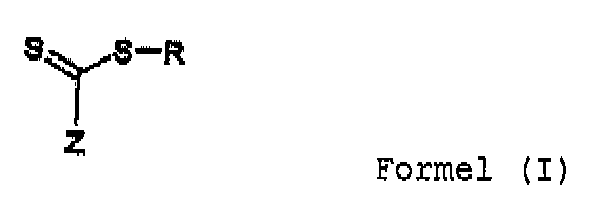
- organic groups Z are alkyl group, arylgroup, thiol, amine, pyrrole, pyridine, alkoxy ,
- R is a moiety having the formula -C-(R 1 ) 2 -Y, wherein R 1 is an alkyl group selected from the group consisting of methyl, ethyl, propyl, isopropyl, butyl group, and Y is an aromatic group selected from the group consisting of phenyl, tolyl, naphtyl group, a CN, an ether group or an ester group.
- R is a -C-(CH 3 ) 2 -CN, -C-(CH 3 ) 2 -Y2 group, wherein Y2 is a phenyl, tolyl or naphtylgroup, or a -C-(CH 3 ) 2 -COOR 2 group, wherein R 2 is a C 1 -C 10 substituted or unsubstituted alkyl group.
- R is chosen from the group consisting of -C-(CH 3 ) 2 -CN, -C-(CH 3 ) 2 -phenyl, -C-(CH 3 ) 2 -tolyl, and -C-(CH 3 ) 2 -COOR 3 , wherein R 3 is methyl, ethyl, propyl or butyl.
- Z is preferably chosen from the group consisting of phenyl, tolyl, naphthyl, thiol, alkyl having from 1 to 10 carbon atoms, and pyrrol groups. More preferably Z is an aromatic group having from 6 to 20 carbon atoms. Most preferably, Z is a phenyl or tolyl group.
- the amount of RAFT agent to be used generally lies between 0,1 and 20 weight %, relative to the blend of polymer(s), monomer(s) and initiator(s).
- RAFT agent the optimum amount of RAFT agent to be added to the composition depends on the amount of photoinitiator present in the composition of the invention, and the amount of dose used to make the polymeric relief structure.
- a R-factor is hereby defined to describe these relations.
- R - factor RAFT initiator * Dose wherein the [RAFT] is the wt% of RAFT agent in the composition (or compound according to formula I), [initiator] is the wt% of a photoinitiator in the composition, and Dose is the radiation dose applied to the composition during build of the structure (in mJ.cm -2 ).
- a linemask with fillfactor 0.5 is a mask comprising parallel lines, wherein 50% of the surface is non-transparant.
- the coating may be applied onto the substrate by any process known in the art of (wet) coating deposition.
- suitable processes are spin coating, dip coating, spray coating, flow coating, meniscus coating, doctor's blading, capillary coating, and roll coating.
- the radiation sensitive ingredients are mixed, preferably with at least one solvent and, optionally, crosslinking initiator to prepare a mixture that is suitable for application to the substrate using the chosen method of application.
- the solvent used is evaporated after applying the coating onto the substrate.
- the coating may after application to the substrate be heated or treated in vacuum to aid evaporation of the solvent.
- solvents examples include 1,4-dioxane, acetone, acetonitrile, chloroform, chlorophenol, cyclohexane, cyclohexanone, cyclopentanone, dichloromethane, diethyl acetate, diethyl ketone, dimethyl carbonate, dimethylformamide, dimethylsulphoxide, ethanol, ethyl acetate, m-cresol, mono- and di-alkyl substituted glycols, N,N-dimethylacetamide, p-chlorophenol, 1,2-propanediol, 1-pentanol, 1-propanol, 2-hexanone, 2-methoxyethanol, 2-methyl-2-propanol, 2-octanone, 2-propanol, 3-pentanone, 4-methyl-2-pentanone, hexafluoroisopropanol, methanol, methyl acetate, butyl acetate, methyl
- Alcohol, ketone and ester based solvents may also be used, although the solubility of acrylates may become an issue with high molecular weight alcohols.
- Halogenated solvents such as dichloromethane and chloroform
- hydrocarbons such as hexanes and cyclohexanes
- the mixtures preferably contain a polymeric material.
- each polymer can be used that forms a homogenous mixture with the other components.
- Well-studied polymers are polymethylmethacrylate, polymethylacrylate, polystyrene, polybenzylmethacrylate, polyisobornylmethacrylate. But also many other polymers may be applied as well.
- the mixture also contains a monomeric compound, being a compound of relatively low molecular weight, i.e. smaller than 1500 daltons, that upon contact with reactive particles, i.e. free radicals or cationic particles, polymerize.
- the monomer or one of the monomers of a monomer mixture contains more than one polymerizing group such that upon polymerization a polymer network is formed.
- the monomers are molecules containing reactive group of the following classes: vinyl, acrylate, methacrylate, epoxide, vinylether, oxetane or thiol-ene.
- the mixture also contains a photosensitive component being the compound that upon exposure to actinic radiation generates the reactive particle, i.e. the free-radicals or cationic particles.
- Examples of monomers suitable for use as polymerizing ingredient and having at least two crosslinkable groups per molecule include monomers containing (meth)acryloyl groups such as trimethylolpropane tri(meth)acrylate, pentaerythritol (meth)acrylate, ethylene glycol di(meth)acrylate, tetraethylene glycol di(meth)acrylate, polyethylene glycol di(meth)acrylate, 1,4-butanediol di(meth)acrylate, 1,6-hexanediol di(meth)acrylate, neopentyl glycol di(meth)acrylate, polybutanediol di(meth)acrylate, tripropyleneglycol di(meth)acrylate, glycerol tri(meth)acrylate, phosphoric acid mono- and di(meth)acrylates, C 7 -C 20 alkyl di(meth)acrylates, trimethylolpropanetrioxyethyl (
- Suitable monomers having only one crosslinking group per molecule include monomers containing a vinyl group, such as N-vinyl pyrrolidone, N-vinyl caprolactam, vinyl imidazole, vinyl pyridine; isobornyl (meth)acrylate, bornyl (meth)acrylate, tricyclodecanyl (meth)acrylate, dicyclopentanyl (meth)acrylate, dicyclopentenyl (meth)acrylate, cyclohexyl (meth)acrylate, benzyl (meth)acrylate, 4-butylcyclohexyl (meth)acrylate, acryloyl morpholine, (meth)acrylic acid, 2-hydroxyethyl (meth)acrylate, 2-hydroxypropyl (meth)acrylate, 2-hydroxybutyl (meth)acrylate, methyl (meth)acrylate, ethyl (meth)acrylate, propyl (meth)acrylate, isopropyl
- Oligomers suitable for use as a radiation sentitive ingredient are for example aromatic or aliphatic urethane acrylates or oligomers based on phenolic resins (ex. bisphenol epoxy diacrylates), and any of the above oligomers chain extended with ethoxylates.
- Urethane oligomers may for example be based on a polyol backbone, for example polyether polyols, polyester polyols, polycarbonate polyols, polycaprolactone polyols, acrylic polyols. These polyols may be used either individually or in combinations of two or more. There are no specific limitations to the manner of polymerization of the structural units in these polyols.
- Any of random polymerization, block polymerization, or graft polymerization is acceptable.
- suitable polyols, polyisocyanates and hydroxylgroup-containing (meth)acrylates for the formation of urethane oligomers are disclosed in WO 00/18696 .
- Combinations of compounds that together may result in the formation of a crosslinked phase and thus in combination are suitable to be used as the reactive diluent are for example carboxylic acids and/or carboxylic anhydrides combined with epoxies, acids combined with hydroxy compounds, especially 2-hydroxyalkylamides, amines combined with isocyanates, for example blocked isocyanate, uretdion or carbodiimide, epoxies combined with amines or with dicyandiamides, hydrazinamides combined with isocyanates, hydroxy compounds combined with isocyanates, for example blocked isocyanate, uretdion or carbodiimide, hydroxy compounds combined with anhydrides, hydroxy compounds combined with (etherified) methylolamide (“amino-resins”), thiols combined with isocyanates, thiols combined with acrylates or other vinylic species (optionally radical initiated), acetoacetate combined with acrylates, and when cationic
- moisture curable isocyanates moisture curable mixtures of alkoxy/acyloxy-silanes, alkoxy titanates, alkoxy zirconates, or urea-, urea/melamine-, melamine- formaldehyde or phenol-formaldehyde (resol, novolac types), or radical curable (peroxide- or photo-initiated) ethylenically unsaturated mono- and polyfunctional monomers and polymers, e.g. acrylates, methacrylates, maleate/vinyl ether), or radical curable (peroxide- or photo-initiated) unsaturated e.g. maleic or fumaric, polyesters in styrene and/or in methacrylates.
- moisture curable isocyanates moisture curable mixtures of alkoxy/acyloxy-silanes, alkoxy titanates, alkoxy zirconates, or urea-, urea/melamine-, melamine- formal
- the applied coating also comprises a polymer, preferably of the same nature as the polymer resulting from the crosslinking of the radiation sensitive ingredients.
- this polymer has a weight-averaged molecular weight (Mw) of at least 20,000 g/mol.
- the polymer when used in the coating step a), preferably has a glass transition temperature of at least 300 K.
- the polymer in the coating used in step a) is dissolved in the monomer(s), present in the radiation sensitive coating of step a) or in the solvent used in the coating of step a) of the process of the present invention.
- Suitable substrates are for example flat or curved, rigid or flexible polymeric substrates, including films of for example polycarbonate, polyester, polyvinyl acetate, polyvinyl pyrollidone, polyvinyl chloride, polyimide, polyethylene naphthalate, polytetrafluoro-ethylene, nylon, polynorbornene or amorphous solids, for example glass or crystalline materials, such as for example silicon or gallium arsenide.
- Metallic substrates may also be used.
- Preferred substrates for use in display applications are for example glass, polynorbornene, polyethersulfone, polyethyleneterephtalate, polyimide, cellulose triacetate, polycarbonate and polyethylenenaphthalate.
- An initiator may be present in the coating to initiate the crosslinking reaction.
- the initiator preferably is a radical photoinitiator.
- the amount of initiator may vary between wide ranges.
- a suitable amount of initiator is for example between above 0 and 10 wt% with respect to total weight of the compounds that take part in the crosslinking reaction.
- the mixture preferably comprises a UV-photo-initiator.
- a photo-initiator is capable of initiating a crosslinking reaction upon absorption of light; thus, UV-photo-initiators absorb light in the Ultra-Violet region of the spectrum. Any known UV-photo-initiators may be used in the process according to the invention.
- the polymerization initiator comprises a mixture of a photo initiator and a thermal initiator.
- cross-linking method that may cause the coating to polymerize and/or crosslink so that a final coating is formed is suitable to be used in the process according to the invention.
- Suitable ways to initiate crosslinking are for example electron beam radiation, electromagnetic radiation (UV, Visible and Near IR), thermally and by adding moisture, in case moisture-curable compounds are used.
- crosslinking is achieved-by UV-radiation.
- the UV-crosslinking may take place through a free radical mechanism or by a cationic mechanism, or a combination thereof.
- the crosslinking is achieved thermally.
- step b) of the process of the present invention the coated substrate resulting form process step a) is locally treated with electromagnetic radiation having a periodic or latent radiation intensity pattering as a result of which a latent image is formed.
- this treatment is performed using UV-light in combination with a mask.
- this treatment is performed by the use of light interference/ holography.
- Still another embodiment is by the use of electron beam lithography.
- the essential feature of the present invention is the use of a RAFT agent in an appropriate amount to exactly tune the rate of polymerization or inhibition time or both for generating relief structures with a high aspect ratio.
- the conditions under which the process steps a)- d) have to be performed are as such known in the art of radiation polymerization.
- temperatures for said process steps preferably a temperature of between 175 and 375 K is used for step b), and preferably a temperature of between 300 and 575 K is used for step c).
- the AR of the polymeric relief structure can be further improved by increasing the UV exposure dose.
- the optimum amount of RAFT agent generally increases when a higher dose of exposure is used.
- the combination of a higher exposure dose and a higher RAFT agent concentration has resulted in a further improvement of the process of the present invention.
- the polymeric relief structures of the present invention have an improved aspect ratio.
- the aspect ratio (AR, being the ratio between the relief height and structure width, both in ⁇ m) of the reliefs of the invention is in general at least 0.075, and more preferably at least 0.12; even more preferably, the AR is at least 0.2.
- the polymeric relief structures of the present invention are applicable in optical components. Examples thereof are quarter wave films and wire grid polarizes for applications in, e.g. LCD's or LED's. Also moth eye or lotus flower structures for self-cleaning surfaces are attainable herewith. Another and preferred embodiment is the use of the polymeric relief structure as a master for replication purposes in organic or inorganic matter. Other applications comprise Anti reflective/anti glare layers; vertically aligned displays (where photo-embossing is used to create the protrusions for alignment of the LCs); Microlenses; Reflectors, transflectors; polarizers; protein arrays, DNA arrays and microcontact printing
- the photopolymer solution is spin-coated onto a glass substrate at 800 RPM. After spin-coating, the sample is heated to 80 °C in order to remove residual traces of solvent resulting in a film of approximately 16 ⁇ m thickness.
- the final formed relief structures were characterized by white light scanning confocal microscopy ( ⁇ Surf, Nanofocus, Germany) using a 20x objective.
- the profiles were further characterized using Scanning Probe Image Processor, SPIP TM software, version 4.1.
- the relief structures are summarized in Table 1. Values of then height of the relief structures have been indicated in nm. The maximum aspect ratio was approximately 0.13.
- Comparative example 1 and 2 that in the absence of a RAFT agent, maximum aspect ratios between 0.05 and 0.13 can be achieved.
- the experimental conditions of comparative example 1 were used. An amount of 2-cyanobut-2-yl dithiobenzoate was added to the photopolymer solution before processing.
- the RAFT agent to initiator ratio was successively changed from 0.1 - 8. During both the illumination and heating step, the film was kept in an air atmosphere.
- the structure heights determined using an optical profilometer for a RAFT to initiator ration of 0.1, 0.2, 0.5, 1, 2, 4 and 8 are shown below in Table 3-9, respectively.
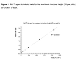
- the relief structures showed a maximum aspect ratio of approximately 0.32 when a RAFT agent to initiator ratio of 2 is used. Table 3. RAFT agent to initiator ratio is 0.1.
- Example 1 The experimental conditions of example 1 were used, except that an inert atmosphere was used during the experiment. An amount of 2-cyanobut-2-yl dithiobenzoate was added to the photopolymer solution before processing.
- the RAFT agent to initiator ratio was successively changed from 0.2 - 1. During both the illumination and heating step, the film was kept in an inert atmosphere.
- the structure heights determined using an optical profilometer for a RAFT to initiator ration of 0.2, 0.5 and 1 are shown below in Table 10-12, respectively.
- the relief structures showed a maximum aspect ratio of approximately 0.42 when a RAFT agent to initiator ratio of 0.5 is used. Table 10.
- RAFT agent to initiator ratio is 0.2.
Landscapes
- Physics & Mathematics (AREA)
- General Physics & Mathematics (AREA)
- Polymerisation Methods In General (AREA)
- Materials For Photolithography (AREA)
- Paints Or Removers (AREA)
- Shaping Of Tube Ends By Bending Or Straightening (AREA)
- Macromolecular Compounds Obtained By Forming Nitrogen-Containing Linkages In General (AREA)
- Polymers With Sulfur, Phosphorus Or Metals In The Main Chain (AREA)
Claims (15)
- Photoprägeverfahren zur Herstellung einer polymeren Reliefstruktur, welches die folgenden Schritte umfasst:(a) Beschichten eines Substrats mit einer Beschichtungszusammensetzung, welche einen oder mehrere strahlungsempfindliche Bestandteile umfasst,(b) lokales Behandeln des beschichteten Substrats mit einer elektromagnetischen Strahlung, welche ein periodisches oder zufälliges Strahlungsintensitätsmuster aufweist, wodurch ein unsichtbares Bild gebildet wird,(c) Polymerisieren und/oder Vernetzen des resultierenden beschichteten Substrats,wobei die Beschichtungszusammensetzung eine Verbindung der Formel I umfasst
- Verfahren nach Anspruch 1, wobei R für eine Einheit der Formel -C-(R1)2Y steht, wobei R1 für eine Alkylgruppe steht, die aus der Gruppe ausgewählt ist, die aus Methyl, Ethyl, Propyl, Isopropyl und Butyl besteht, und wobei Y für eine aromatische Gruppe, die aus der Gruppe ausgewählt ist, die aus Phenyl, Tolyl und Naphthyl besteht, oder für eine CN-Gruppe oder eine Ethergruppe oder eine Estergruppe steht.
- Verfahren nach Anspruch 1, wobei R für eine -C-(CH3)2-CN-Gruppe, eine -C-(CH3)2-Y2-Gruppe, bei welcher Y2 für eine Phenyl-, Tolyl- oder Naphthylgruppe steht, oder eine -C-(CH3)2-COOR2-Gruppe steht, bei welcher R2 für eine C1-10-substituierte oder unsubstituierte Alkylgruppe steht.
- Verfahren nach einem der Ansprüche 1 bis 3, wobei R aus der Gruppe ausgewählt ist, die aus -C-(CH3)2-CN, -C-(CH3)2-phenyl, -C-(CH3)2-tolyl und -C-(CH3)2-COOR3 besteht, wobei R3 für Methyl, Ethyl, Propyl oder Butyl steht.
- Verfahren nach einem der Ansprüche 1 bis 4, wobei Z aus der Gruppe ausgewählt ist, die aus Phenyl-, Tolyl-, Naphthyl-, Thiol-, Alkylgruppen mit 1 bis 10 Kohlenstoffatomen und Pyrrolgruppen besteht.
- Verfahren nach einem der Ansprüche 1 bis 5, wobei Z für eine aromatische Gruppe mit 6 bis 20 Kohlenstoffatomen steht.
- Verfahren nach einem der Ansprüche 1 bis 6, wobei Z für eine Phenyl- oder Tolylgruppe steht.
- Verfahren nach einem der Ansprüche 1 bis 7, wobei die Beschichtungszusammensetzung ein Gemisch aus mindestens einem Polymer, mindestens einem Monomer, einem Photoinitiator und einer Verbindung der Formel I in einer Menge von 0,1 bis 20 Gew.-% (bezogen auf das Gemisch aus Polymer(en), Monomer(en) und Initiator(en)) umfasst.
- Verfahren nach Anspruch 8, wobei die Menge der Verbindung der Formel I, die Photoinitiatorkonzentration und die Stärke der elektromagnetischen Bestrahlung gemäß der folgenden Formel in Beziehung zueinander stehen:

wobei [RAFT] für den Gew.-Prozentsatz des Kettenüberträgers der Formel I für den Reversible Addition Fragmentation Chain Transfer steht, [Initiator] für den Gew.-Prozentsatz an Photoinitiator in der Zusammensetzung steht und Dosis für die Bestrahlungsdosis (in mJ/cm2) steht, die während des Aufbaus der Struktur auf die Zusammensetzung angewendet wird, und wobei der R-Faktor im Bereich von 0,0001 bis 0,005 liegt. - Verfahren nach Anspruch 9, wobei der R-Faktor im Bereich von 0,0005 bis 0,004 liegt.
- Verfahren nach einem der Ansprüche 1 bis 10, wobei die Schritte b) und c) kombiniert werden.
- Verfahren nach einem der Ansprüche 1 bis 11, wobei zwischen den Schritten a) und b) das Lösungsmittel entfernt wird.
- Gegenstand, welcher eine polymere Reliefstruktur umfasst, wie sie über ein Verfahren nach einem der Ansprüche 1 bis 12 hergestellt wird.
- Optische Komponente, welche eine polymere Reliefstruktur umfasst, wie sie über ein Verfahren nach einem der Ansprüche 1 bis 12 hergestellt wird.
- Urform zu Nachbildungszwecken mit organischem oder anorganischem Material, welche eine polymere Reliefstruktur umfasst, wie sie über ein Verfahren nach einem der Ansprüche 1 bis 12 hergestellt wird.
Priority Applications (1)
| Application Number | Priority Date | Filing Date | Title |
|---|---|---|---|
| EP08759973A EP2156247B1 (de) | 2007-06-11 | 2008-05-23 | Prozess zur herstellung einer polymerischen relief struktur |
Applications Claiming Priority (3)
| Application Number | Priority Date | Filing Date | Title |
|---|---|---|---|
| EP07109998A EP2019336A1 (de) | 2007-06-11 | 2007-06-11 | Verfahren zur Herstellung einer Polymerreliefstruktur |
| EP08759973A EP2156247B1 (de) | 2007-06-11 | 2008-05-23 | Prozess zur herstellung einer polymerischen relief struktur |
| PCT/EP2008/056373 WO2008151915A1 (en) | 2007-06-11 | 2008-05-23 | Process for preparing a polymeric relief structure |
Publications (2)
| Publication Number | Publication Date |
|---|---|
| EP2156247A1 EP2156247A1 (de) | 2010-02-24 |
| EP2156247B1 true EP2156247B1 (de) | 2010-11-03 |
Family
ID=38626528
Family Applications (2)
| Application Number | Title | Priority Date | Filing Date |
|---|---|---|---|
| EP07109998A Withdrawn EP2019336A1 (de) | 2007-06-11 | 2007-06-11 | Verfahren zur Herstellung einer Polymerreliefstruktur |
| EP08759973A Not-in-force EP2156247B1 (de) | 2007-06-11 | 2008-05-23 | Prozess zur herstellung einer polymerischen relief struktur |
Family Applications Before (1)
| Application Number | Title | Priority Date | Filing Date |
|---|---|---|---|
| EP07109998A Withdrawn EP2019336A1 (de) | 2007-06-11 | 2007-06-11 | Verfahren zur Herstellung einer Polymerreliefstruktur |
Country Status (6)
| Country | Link |
|---|---|
| US (1) | US20100279074A1 (de) |
| EP (2) | EP2019336A1 (de) |
| JP (1) | JP2010532394A (de) |
| AT (1) | ATE487166T1 (de) |
| DE (1) | DE602008003333D1 (de) |
| WO (1) | WO2008151915A1 (de) |
Families Citing this family (5)
| Publication number | Priority date | Publication date | Assignee | Title |
|---|---|---|---|---|
| EP2109005A1 (de) * | 2008-04-07 | 2009-10-14 | Stichting Dutch Polymer Institute | Verfahren zur Herstellung einer Polymerreliefstruktur |
| WO2012025316A1 (en) * | 2010-08-26 | 2012-03-01 | Asml Netherlands B.V. | Imprint lithography method and imprintable medium |
| EP2592477A1 (de) * | 2011-11-14 | 2013-05-15 | Stichting Dutch Polymer Institute | Durchgehendes Verfahren zur Herstellung eines Substrats mit Reliefsstruktur |
| JP5579217B2 (ja) * | 2012-03-27 | 2014-08-27 | 富士フイルム株式会社 | 平版印刷版原版 |
| EP3114189B1 (de) * | 2014-03-04 | 2018-07-04 | Nanoco Technologies Ltd | Verfahren zur herstellung von quantenpunkt-polymerfolien |
Family Cites Families (11)
| Publication number | Priority date | Publication date | Assignee | Title |
|---|---|---|---|---|
| JPH10228108A (ja) * | 1997-02-17 | 1998-08-25 | Hitachi Chem Co Ltd | 感光性組成物、感光材料、レリーフパターンの製造法及びポリイミドパターンの製造法 |
| US20040101782A1 (en) * | 2002-11-27 | 2004-05-27 | General Electric Company | Method for making optical device structures |
| EP1649319A1 (de) * | 2003-07-17 | 2006-04-26 | Koninklijke Philips Electronics N.V. | Methode zur herstellung eines reflektors und flüssigkristallanzeige, die einen solchen reflektor beinhaltet |
| TWI275597B (en) * | 2003-08-05 | 2007-03-11 | Ind Tech Res Inst | Resin with low polydispersity index, and preparation process, and use thereof |
| CA2556684A1 (en) * | 2004-02-19 | 2005-09-01 | Stichting Dutch Polymer Institute | Process for preparing a polymeric relief structure |
| CA2790003C (en) * | 2004-10-04 | 2014-03-11 | The University Of Sydney | Surface polymerisation process and polymer product using raft agent |
| WO2006085741A1 (en) * | 2005-02-09 | 2006-08-17 | Stichting Dutch Polymer Institute | Process for preparing a polymeric relief structure |
| WO2006086841A1 (en) * | 2005-02-15 | 2006-08-24 | Rpo Pty Limited | Photolithographic patterning of polymeric materials |
| US7677877B2 (en) * | 2005-11-04 | 2010-03-16 | Asml Netherlands B.V. | Imprint lithography |
| DE602007011639D1 (de) * | 2006-08-21 | 2011-02-10 | Koninkl Philips Electronics Nv | Methode zur Herstellung einer versiegelten Zellstruktur |
| EP2256788A4 (de) * | 2008-03-07 | 2011-03-30 | Showa Denko Kk | Uv-nanoimprintverfahren, harzabdruckform und herstellungsverfahren dafür, magnetisches aufzeichnungsmedium und verfahren zu seiner herstellung sowie magnetisches aufzeichnungs-/wiedergabegerät |
-
2007
- 2007-06-11 EP EP07109998A patent/EP2019336A1/de not_active Withdrawn
-
2008
- 2008-05-23 JP JP2010511568A patent/JP2010532394A/ja active Pending
- 2008-05-23 DE DE602008003333T patent/DE602008003333D1/de active Active
- 2008-05-23 AT AT08759973T patent/ATE487166T1/de not_active IP Right Cessation
- 2008-05-23 WO PCT/EP2008/056373 patent/WO2008151915A1/en not_active Ceased
- 2008-05-23 EP EP08759973A patent/EP2156247B1/de not_active Not-in-force
- 2008-05-23 US US12/663,916 patent/US20100279074A1/en not_active Abandoned
Also Published As
| Publication number | Publication date |
|---|---|
| EP2156247A1 (de) | 2010-02-24 |
| DE602008003333D1 (de) | 2010-12-16 |
| WO2008151915A1 (en) | 2008-12-18 |
| EP2019336A1 (de) | 2009-01-28 |
| US20100279074A1 (en) | 2010-11-04 |
| JP2010532394A (ja) | 2010-10-07 |
| ATE487166T1 (de) | 2010-11-15 |
Similar Documents
| Publication | Publication Date | Title |
|---|---|---|
| US20100028816A1 (en) | Process for preparing a polymeric relief structure | |
| EP2019336A1 (de) | Verfahren zur Herstellung einer Polymerreliefstruktur | |
| US8568962B2 (en) | Process for preparing a polymeric relief structure | |
| TWI382993B (zh) | 光波導用感光性樹脂組成物、光波導及其製造方法 | |
| JPWO2002006859A1 (ja) | 光拡散フィルム | |
| US20090233181A1 (en) | Porous holographic film | |
| US8927178B2 (en) | Process for preparing a polymeric relief structure | |
| WO2001031401A1 (en) | Self-processing of diffractive optical components in hybrid sol-gel glasses | |
| US20070202421A1 (en) | Process For Preparing A Polymeric Relief Structure | |
| CN113527929B (zh) | 光致聚合物组合物以及光栅 | |
| CN112114496B (zh) | 感光性树脂、其制备方法、感光性树脂组合物及着色间隔物 | |
| KR20060134088A (ko) | 중합체 양각 구조체의 제조방법 | |
| US20020192601A1 (en) | Process for the production of film having refractive index distribution | |
| KR20060084057A (ko) | 직접 광패터닝에 의한 평판형 멀티모드 광도파로 제조방법 | |
| EP2592477A1 (de) | Durchgehendes Verfahren zur Herstellung eines Substrats mit Reliefsstruktur |
Legal Events
| Date | Code | Title | Description |
|---|---|---|---|
| PUAI | Public reference made under article 153(3) epc to a published international application that has entered the european phase |
Free format text: ORIGINAL CODE: 0009012 |
|
| 17P | Request for examination filed |
Effective date: 20091222 |
|
| AK | Designated contracting states |
Kind code of ref document: A1 Designated state(s): AT BE BG CH CY CZ DE DK EE ES FI FR GB GR HR HU IE IS IT LI LT LU LV MC MT NL NO PL PT RO SE SI SK TR |
|
| AX | Request for extension of the european patent |
Extension state: AL BA MK RS |
|
| GRAP | Despatch of communication of intention to grant a patent |
Free format text: ORIGINAL CODE: EPIDOSNIGR1 |
|
| GRAS | Grant fee paid |
Free format text: ORIGINAL CODE: EPIDOSNIGR3 |
|
| DAX | Request for extension of the european patent (deleted) | ||
| GRAA | (expected) grant |
Free format text: ORIGINAL CODE: 0009210 |
|
| AK | Designated contracting states |
Kind code of ref document: B1 Designated state(s): AT BE BG CH CY CZ DE DK EE ES FI FR GB GR HR HU IE IS IT LI LT LU LV MC MT NL NO PL PT RO SE SI SK TR |
|
| REG | Reference to a national code |
Ref country code: GB Ref legal event code: FG4D |
|
| REG | Reference to a national code |
Ref country code: CH Ref legal event code: EP |
|
| REG | Reference to a national code |
Ref country code: IE Ref legal event code: FG4D |
|
| REF | Corresponds to: |
Ref document number: 602008003333 Country of ref document: DE Date of ref document: 20101216 Kind code of ref document: P |
|
| REG | Reference to a national code |
Ref country code: NL Ref legal event code: VDEP Effective date: 20101103 |
|
| LTIE | Lt: invalidation of european patent or patent extension |
Effective date: 20101103 |
|
| PG25 | Lapsed in a contracting state [announced via postgrant information from national office to epo] |
Ref country code: NO Free format text: LAPSE BECAUSE OF FAILURE TO SUBMIT A TRANSLATION OF THE DESCRIPTION OR TO PAY THE FEE WITHIN THE PRESCRIBED TIME-LIMIT Effective date: 20110203 Ref country code: LT Free format text: LAPSE BECAUSE OF FAILURE TO SUBMIT A TRANSLATION OF THE DESCRIPTION OR TO PAY THE FEE WITHIN THE PRESCRIBED TIME-LIMIT Effective date: 20101103 |
|
| PG25 | Lapsed in a contracting state [announced via postgrant information from national office to epo] |
Ref country code: HR Free format text: LAPSE BECAUSE OF FAILURE TO SUBMIT A TRANSLATION OF THE DESCRIPTION OR TO PAY THE FEE WITHIN THE PRESCRIBED TIME-LIMIT Effective date: 20101103 Ref country code: SI Free format text: LAPSE BECAUSE OF FAILURE TO SUBMIT A TRANSLATION OF THE DESCRIPTION OR TO PAY THE FEE WITHIN THE PRESCRIBED TIME-LIMIT Effective date: 20101103 Ref country code: FI Free format text: LAPSE BECAUSE OF FAILURE TO SUBMIT A TRANSLATION OF THE DESCRIPTION OR TO PAY THE FEE WITHIN THE PRESCRIBED TIME-LIMIT Effective date: 20101103 Ref country code: PT Free format text: LAPSE BECAUSE OF FAILURE TO SUBMIT A TRANSLATION OF THE DESCRIPTION OR TO PAY THE FEE WITHIN THE PRESCRIBED TIME-LIMIT Effective date: 20110303 Ref country code: AT Free format text: LAPSE BECAUSE OF FAILURE TO SUBMIT A TRANSLATION OF THE DESCRIPTION OR TO PAY THE FEE WITHIN THE PRESCRIBED TIME-LIMIT Effective date: 20101103 Ref country code: LV Free format text: LAPSE BECAUSE OF FAILURE TO SUBMIT A TRANSLATION OF THE DESCRIPTION OR TO PAY THE FEE WITHIN THE PRESCRIBED TIME-LIMIT Effective date: 20101103 Ref country code: NL Free format text: LAPSE BECAUSE OF FAILURE TO SUBMIT A TRANSLATION OF THE DESCRIPTION OR TO PAY THE FEE WITHIN THE PRESCRIBED TIME-LIMIT Effective date: 20101103 Ref country code: SE Free format text: LAPSE BECAUSE OF FAILURE TO SUBMIT A TRANSLATION OF THE DESCRIPTION OR TO PAY THE FEE WITHIN THE PRESCRIBED TIME-LIMIT Effective date: 20101103 Ref country code: BG Free format text: LAPSE BECAUSE OF FAILURE TO SUBMIT A TRANSLATION OF THE DESCRIPTION OR TO PAY THE FEE WITHIN THE PRESCRIBED TIME-LIMIT Effective date: 20110203 Ref country code: IS Free format text: LAPSE BECAUSE OF FAILURE TO SUBMIT A TRANSLATION OF THE DESCRIPTION OR TO PAY THE FEE WITHIN THE PRESCRIBED TIME-LIMIT Effective date: 20110303 |
|
| PG25 | Lapsed in a contracting state [announced via postgrant information from national office to epo] |
Ref country code: GR Free format text: LAPSE BECAUSE OF FAILURE TO SUBMIT A TRANSLATION OF THE DESCRIPTION OR TO PAY THE FEE WITHIN THE PRESCRIBED TIME-LIMIT Effective date: 20110204 |
|
| PG25 | Lapsed in a contracting state [announced via postgrant information from national office to epo] |
Ref country code: EE Free format text: LAPSE BECAUSE OF FAILURE TO SUBMIT A TRANSLATION OF THE DESCRIPTION OR TO PAY THE FEE WITHIN THE PRESCRIBED TIME-LIMIT Effective date: 20101103 Ref country code: CZ Free format text: LAPSE BECAUSE OF FAILURE TO SUBMIT A TRANSLATION OF THE DESCRIPTION OR TO PAY THE FEE WITHIN THE PRESCRIBED TIME-LIMIT Effective date: 20101103 Ref country code: BE Free format text: LAPSE BECAUSE OF FAILURE TO SUBMIT A TRANSLATION OF THE DESCRIPTION OR TO PAY THE FEE WITHIN THE PRESCRIBED TIME-LIMIT Effective date: 20101103 Ref country code: ES Free format text: LAPSE BECAUSE OF FAILURE TO SUBMIT A TRANSLATION OF THE DESCRIPTION OR TO PAY THE FEE WITHIN THE PRESCRIBED TIME-LIMIT Effective date: 20110214 |
|
| PG25 | Lapsed in a contracting state [announced via postgrant information from national office to epo] |
Ref country code: DK Free format text: LAPSE BECAUSE OF FAILURE TO SUBMIT A TRANSLATION OF THE DESCRIPTION OR TO PAY THE FEE WITHIN THE PRESCRIBED TIME-LIMIT Effective date: 20101103 Ref country code: PL Free format text: LAPSE BECAUSE OF FAILURE TO SUBMIT A TRANSLATION OF THE DESCRIPTION OR TO PAY THE FEE WITHIN THE PRESCRIBED TIME-LIMIT Effective date: 20101103 Ref country code: RO Free format text: LAPSE BECAUSE OF FAILURE TO SUBMIT A TRANSLATION OF THE DESCRIPTION OR TO PAY THE FEE WITHIN THE PRESCRIBED TIME-LIMIT Effective date: 20101103 Ref country code: SK Free format text: LAPSE BECAUSE OF FAILURE TO SUBMIT A TRANSLATION OF THE DESCRIPTION OR TO PAY THE FEE WITHIN THE PRESCRIBED TIME-LIMIT Effective date: 20101103 |
|
| PLBE | No opposition filed within time limit |
Free format text: ORIGINAL CODE: 0009261 |
|
| STAA | Information on the status of an ep patent application or granted ep patent |
Free format text: STATUS: NO OPPOSITION FILED WITHIN TIME LIMIT |
|
| 26N | No opposition filed |
Effective date: 20110804 |
|
| REG | Reference to a national code |
Ref country code: DE Ref legal event code: R097 Ref document number: 602008003333 Country of ref document: DE Effective date: 20110804 |
|
| PG25 | Lapsed in a contracting state [announced via postgrant information from national office to epo] |
Ref country code: MC Free format text: LAPSE BECAUSE OF NON-PAYMENT OF DUE FEES Effective date: 20110531 Ref country code: IT Free format text: LAPSE BECAUSE OF FAILURE TO SUBMIT A TRANSLATION OF THE DESCRIPTION OR TO PAY THE FEE WITHIN THE PRESCRIBED TIME-LIMIT Effective date: 20101103 Ref country code: MT Free format text: LAPSE BECAUSE OF FAILURE TO SUBMIT A TRANSLATION OF THE DESCRIPTION OR TO PAY THE FEE WITHIN THE PRESCRIBED TIME-LIMIT Effective date: 20101103 |
|
| REG | Reference to a national code |
Ref country code: IE Ref legal event code: MM4A |
|
| PG25 | Lapsed in a contracting state [announced via postgrant information from national office to epo] |
Ref country code: IE Free format text: LAPSE BECAUSE OF NON-PAYMENT OF DUE FEES Effective date: 20110523 |
|
| REG | Reference to a national code |
Ref country code: CH Ref legal event code: PL |
|
| PG25 | Lapsed in a contracting state [announced via postgrant information from national office to epo] |
Ref country code: LI Free format text: LAPSE BECAUSE OF NON-PAYMENT OF DUE FEES Effective date: 20120531 Ref country code: CH Free format text: LAPSE BECAUSE OF NON-PAYMENT OF DUE FEES Effective date: 20120531 |
|
| PG25 | Lapsed in a contracting state [announced via postgrant information from national office to epo] |
Ref country code: CY Free format text: LAPSE BECAUSE OF EXPIRATION OF PROTECTION Effective date: 20101103 Ref country code: LU Free format text: LAPSE BECAUSE OF NON-PAYMENT OF DUE FEES Effective date: 20110523 |
|
| PGFP | Annual fee paid to national office [announced via postgrant information from national office to epo] |
Ref country code: GB Payment date: 20130522 Year of fee payment: 6 Ref country code: DE Payment date: 20130515 Year of fee payment: 6 |
|
| PGFP | Annual fee paid to national office [announced via postgrant information from national office to epo] |
Ref country code: FR Payment date: 20130531 Year of fee payment: 6 |
|
| PG25 | Lapsed in a contracting state [announced via postgrant information from national office to epo] |
Ref country code: TR Free format text: LAPSE BECAUSE OF FAILURE TO SUBMIT A TRANSLATION OF THE DESCRIPTION OR TO PAY THE FEE WITHIN THE PRESCRIBED TIME-LIMIT Effective date: 20101103 |
|
| PG25 | Lapsed in a contracting state [announced via postgrant information from national office to epo] |
Ref country code: HU Free format text: LAPSE BECAUSE OF FAILURE TO SUBMIT A TRANSLATION OF THE DESCRIPTION OR TO PAY THE FEE WITHIN THE PRESCRIBED TIME-LIMIT Effective date: 20101103 |
|
| REG | Reference to a national code |
Ref country code: DE Ref legal event code: R119 Ref document number: 602008003333 Country of ref document: DE |
|
| GBPC | Gb: european patent ceased through non-payment of renewal fee |
Effective date: 20140523 |
|
| REG | Reference to a national code |
Ref country code: DE Ref legal event code: R119 Ref document number: 602008003333 Country of ref document: DE Effective date: 20141202 |
|
| REG | Reference to a national code |
Ref country code: FR Ref legal event code: ST Effective date: 20150130 |
|
| PG25 | Lapsed in a contracting state [announced via postgrant information from national office to epo] |
Ref country code: DE Free format text: LAPSE BECAUSE OF NON-PAYMENT OF DUE FEES Effective date: 20141202 |
|
| PG25 | Lapsed in a contracting state [announced via postgrant information from national office to epo] |
Ref country code: GB Free format text: LAPSE BECAUSE OF NON-PAYMENT OF DUE FEES Effective date: 20140523 Ref country code: FR Free format text: LAPSE BECAUSE OF NON-PAYMENT OF DUE FEES Effective date: 20140602 |